Southern
Pacific 9010
Electrical Work
Page 1
Page 1
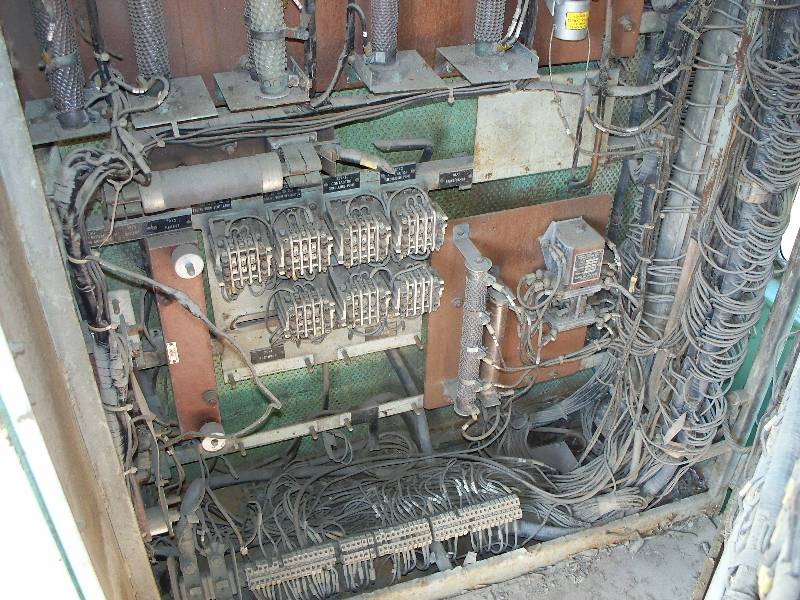
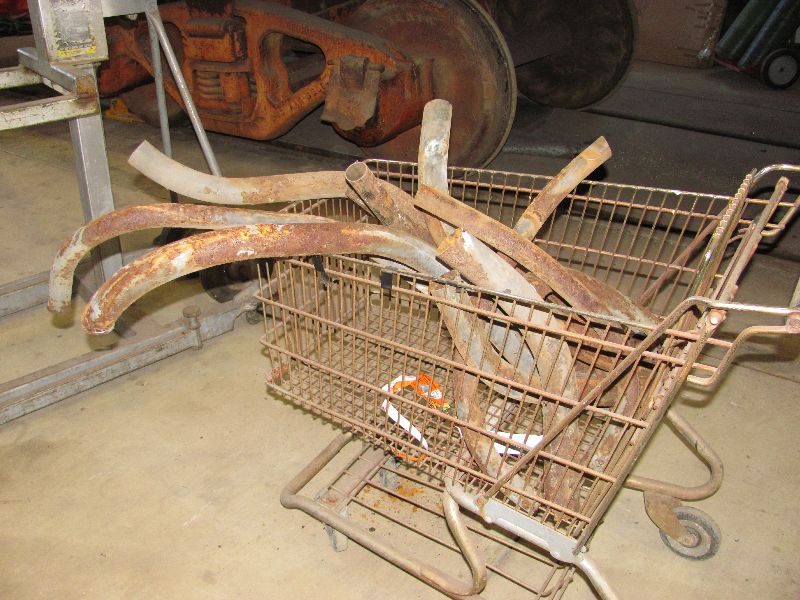
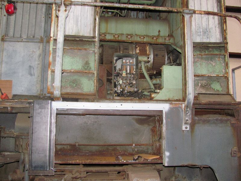
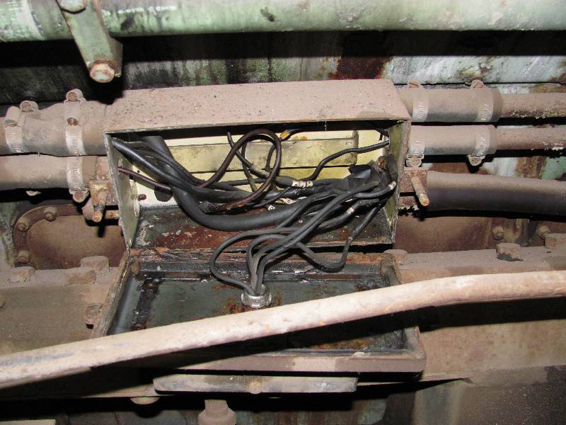
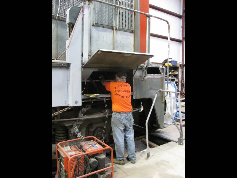
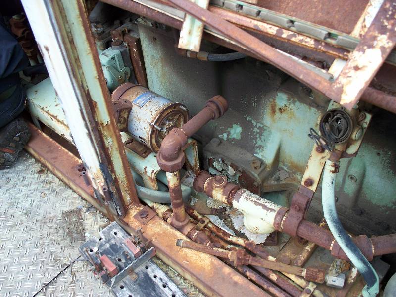
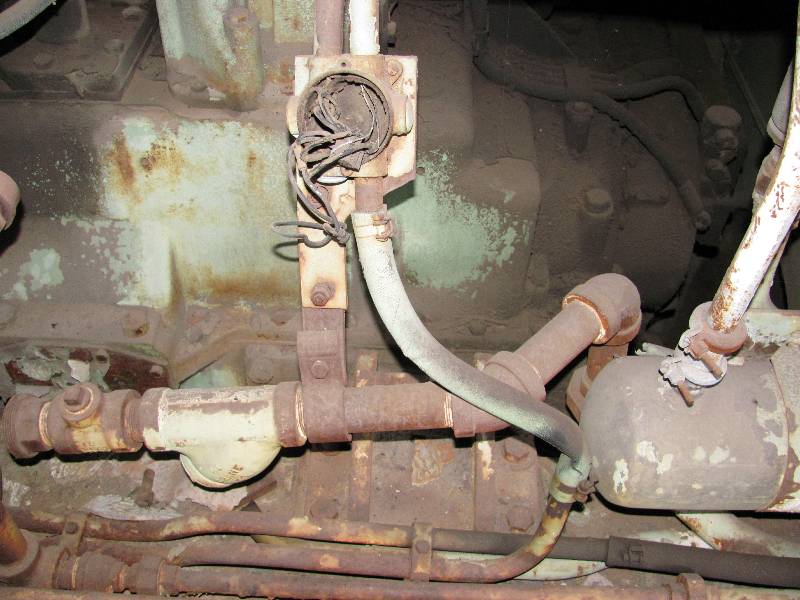
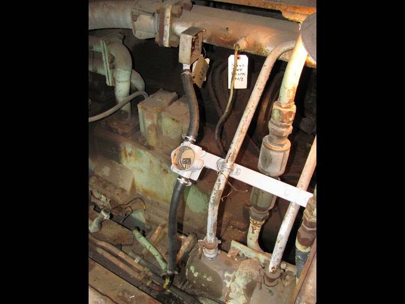
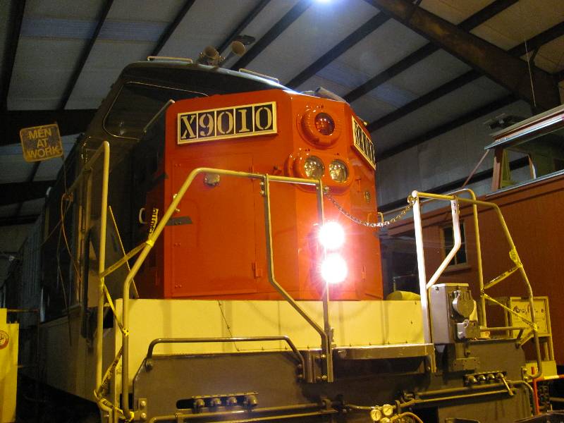
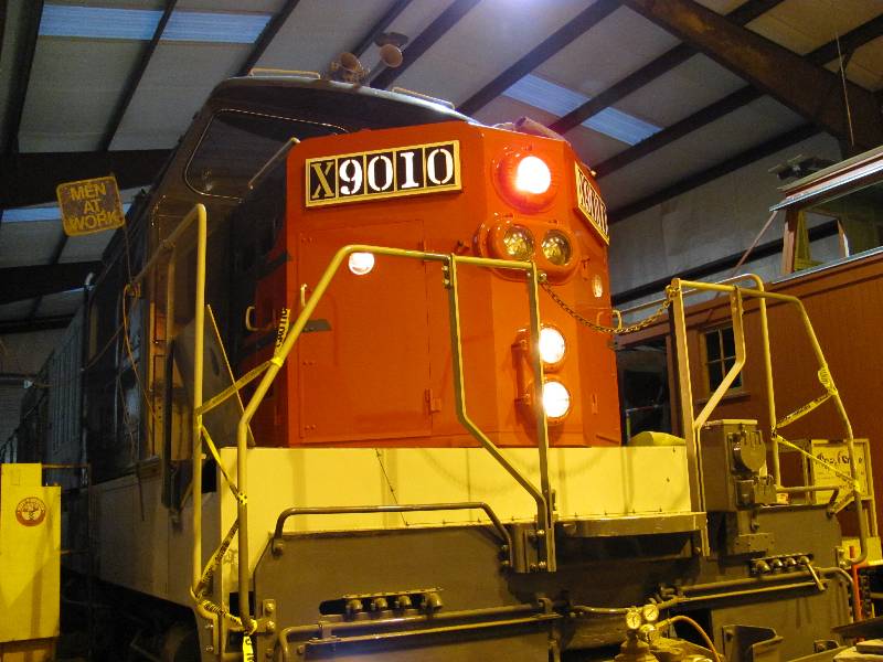
The 9010 has sustained a lot of damage to the electrical system over the past 25 years. This is mainly due to the actions of copper thieves while the locomotive was in storage in Sacramento. There is a lot of wiring missing which apparently was removed by the Southern Pacific during the camera car conversion. Here are a few photos illustrating the problems we face.
 |
 |
 |
 |
 |
-- Update October 30, 2009 --
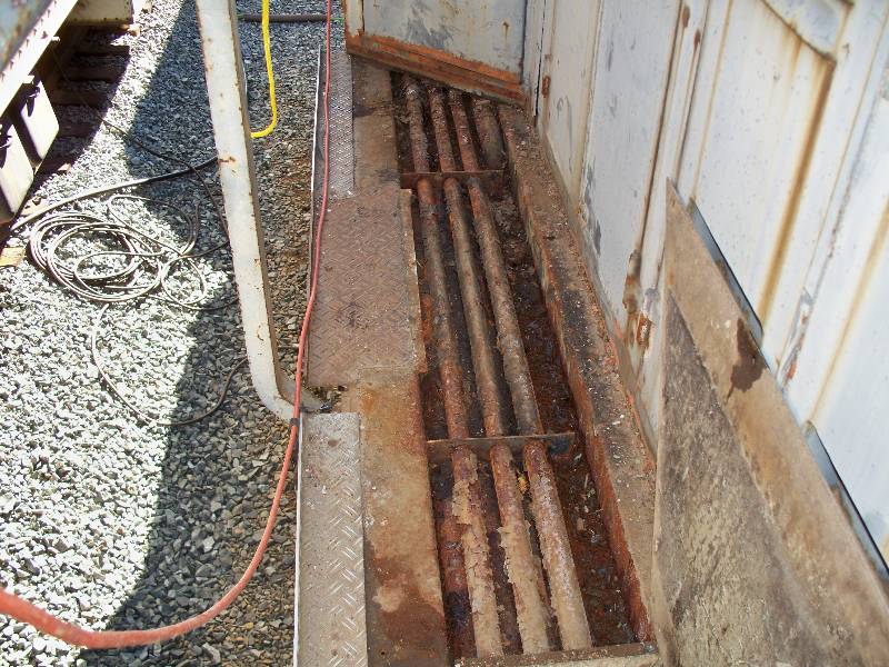
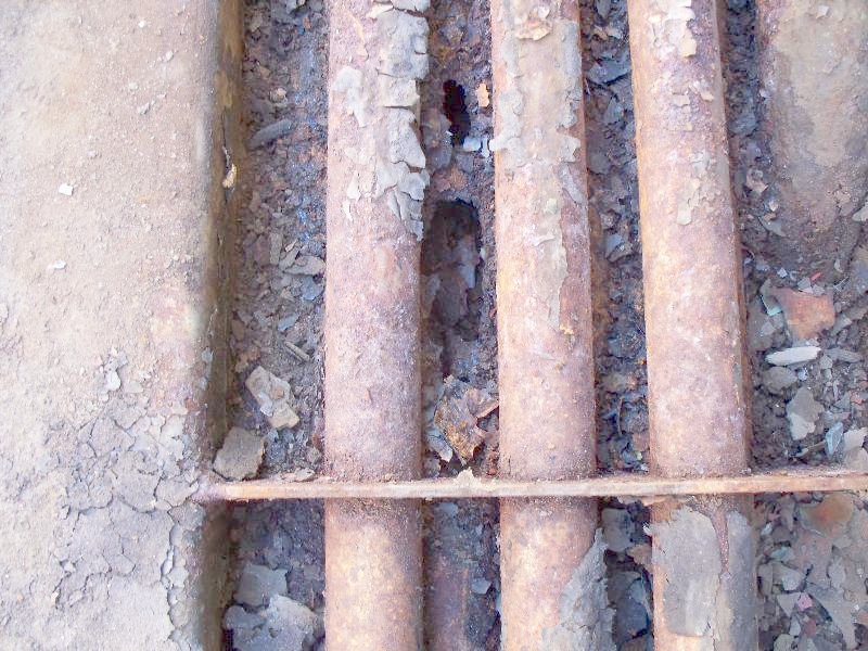
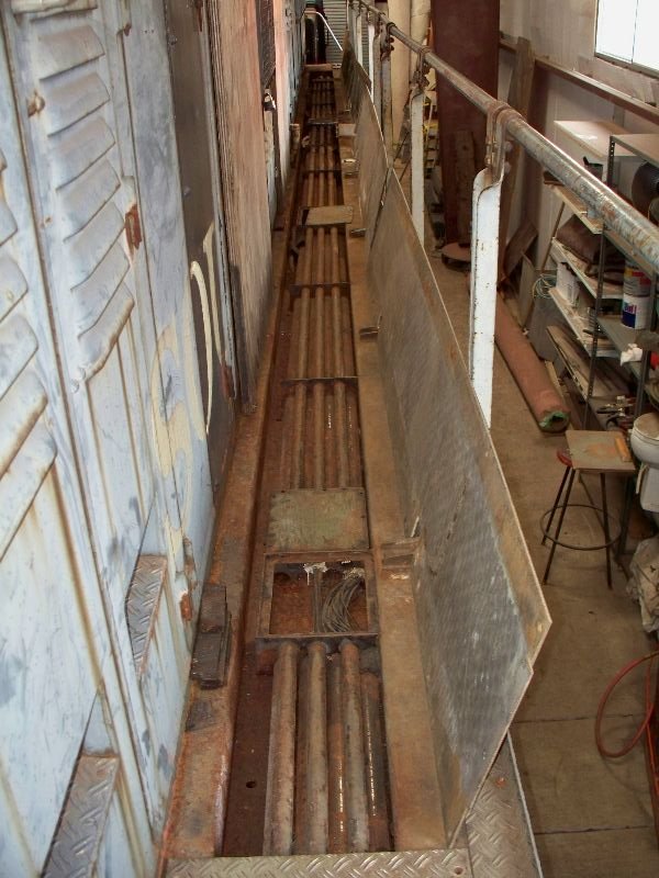
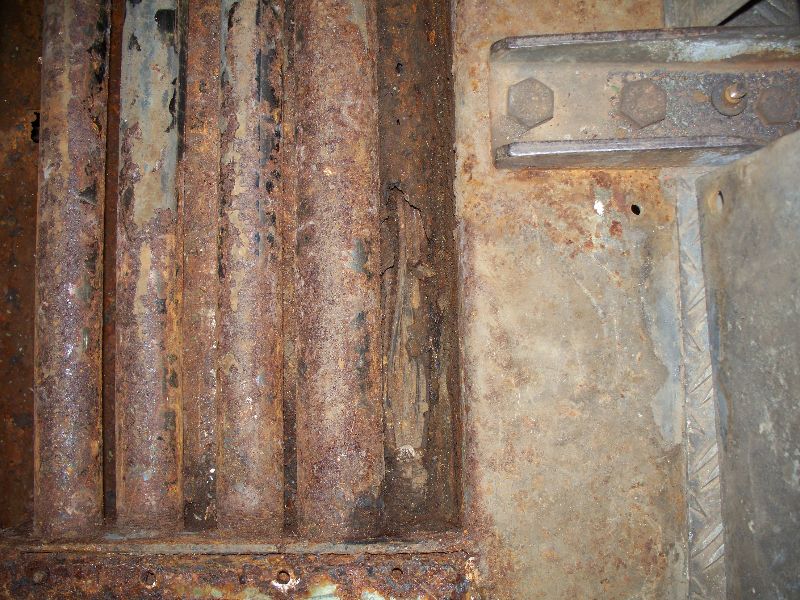
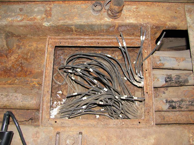
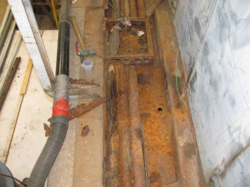
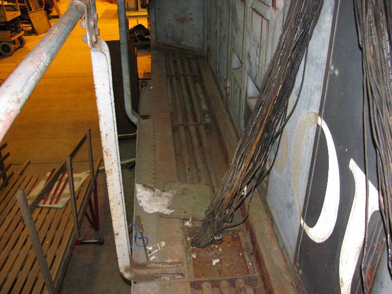
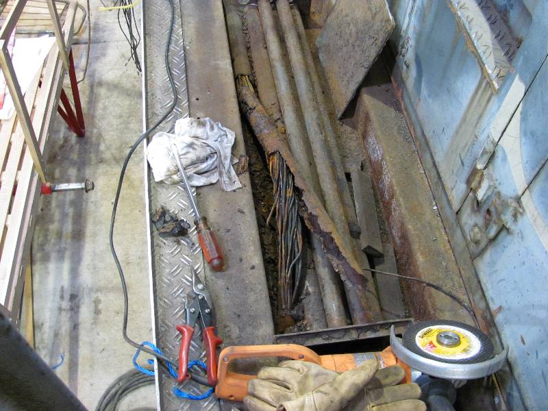
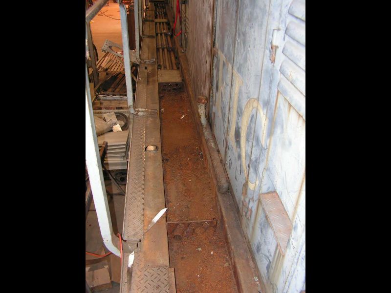
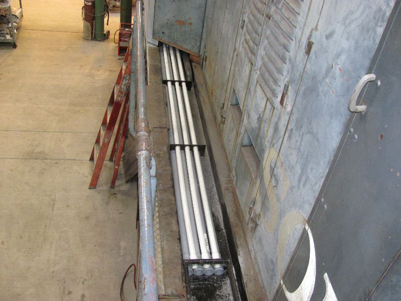
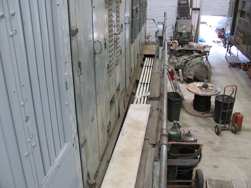
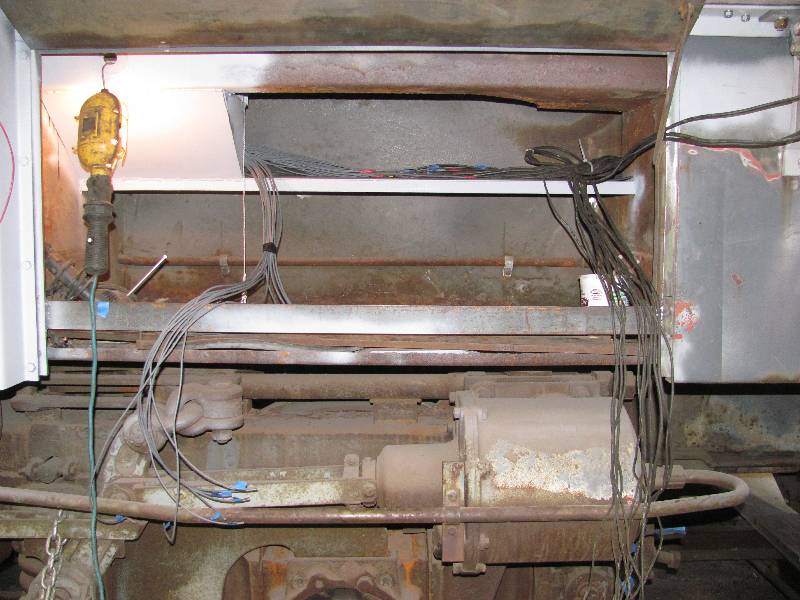
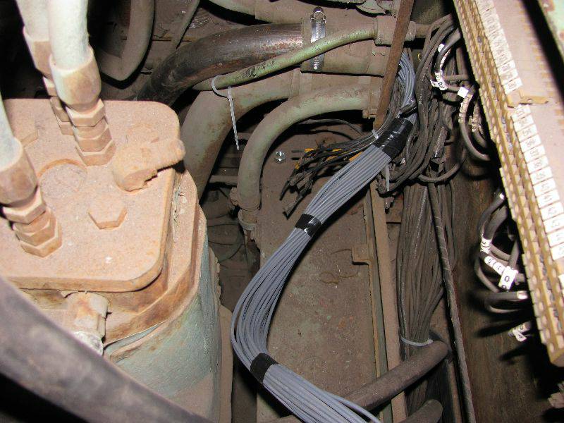
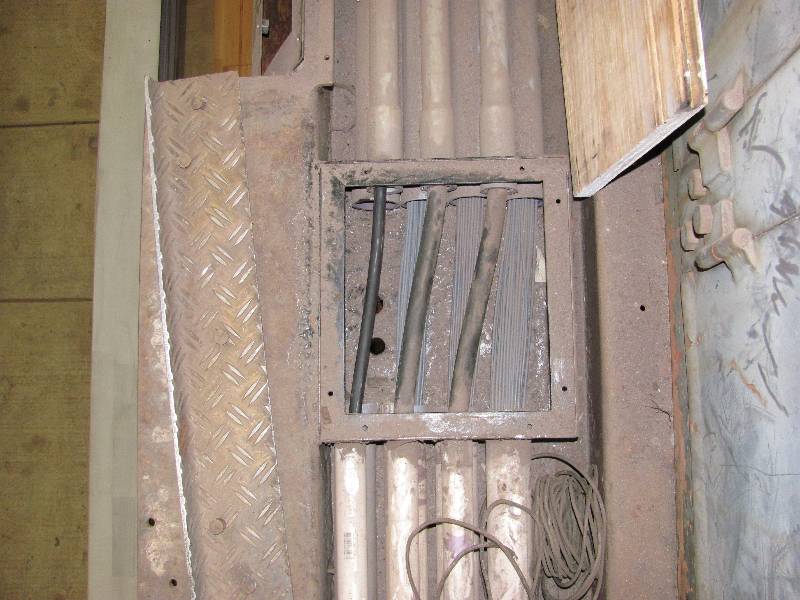
The wiring that runs from the electrical cabinet in the cab to the rear locomotive's rear end travels through a series of metal conduits which are located under the fireman's side walkway. I needed to figure out which conduit went to the battery boxes and main switch so I removed the first floor panel behind the engineer's door. Much to my dismay, I found that the channel in which the conduits lay is full of crap and corrosion. In fact, at least one of the conduits is rotted completely through on its top surface. More exploratory work will have to be done in this area. I also removed the rearmost panel on the same side and found that all 8 of the conduits run all the way from the front to the rear. The markings on the bottom of the rear plate leave something of a mystery as there are only 6 plates on that side so "L8" cannot mean "Left 8". We later learned that "L8" means "Lok 8" as the 9010 was the 8th production locomotive. The number 6 indicates the sixth plate, counting from the cab.
 |
 |
 |
 |
 |
 |
-- Update September 25, 2010 --
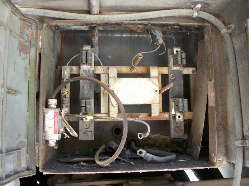
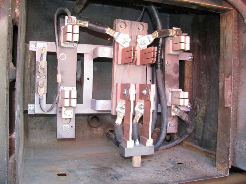
As can be seen in the photos at the top of this page, the main battery switch was "liberated" by the copper thieves in Sacramento. It was originally an unusual rotary switch and a lot of research revealed that a replacement was not available in this country, if at all. So, it was replaced with a conventional knife switch which will do the job nicely.
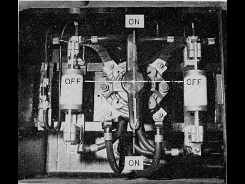 Krauss
Maffei Photo
|
 |
 |
-- Update October 05, 2010 --
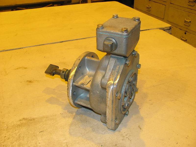
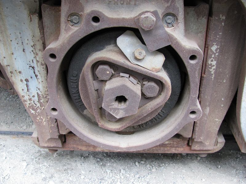
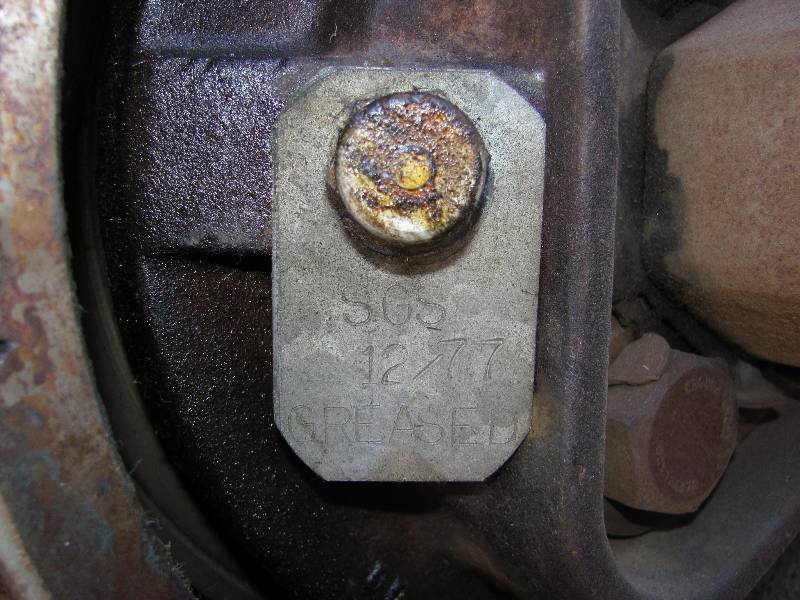
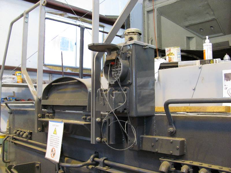
While not strictly electrical work, the speedometer drives produce electrical pulses so their story is put in this section. As originally equipped, the 9010 had devices mounted on 3 of the axle ends. They were, a Barco mechanical drive on the left end of axle 2, a General Electric pulse drive on the left end of axle 4 and another GE drive on the right end of axle 3. During the years of service and the Camera Car conversion, the drive adapters were moved around but luckily, we have the 3 drive adapters we need. Two of them had to be moved and in one case, the bearing end cap had to be changed. Photo 2 shows the wrong (speedometer drive speaking) cap found on the right end of axle 3 and the correct cap on the left side. The two caps were exchanged and the adapter mounted. During the change, the tag in photo 4 was noticed. All of the bearings have the same tags with the same date which is 9 years after the Camera Car entered service and about 10 years before it was put out of service. The flexible conduits between the drives and the body have yet to be installed.
 |
 |
 |
 |
 |
 |
 |
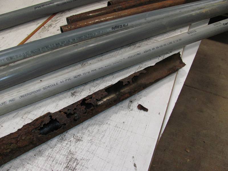
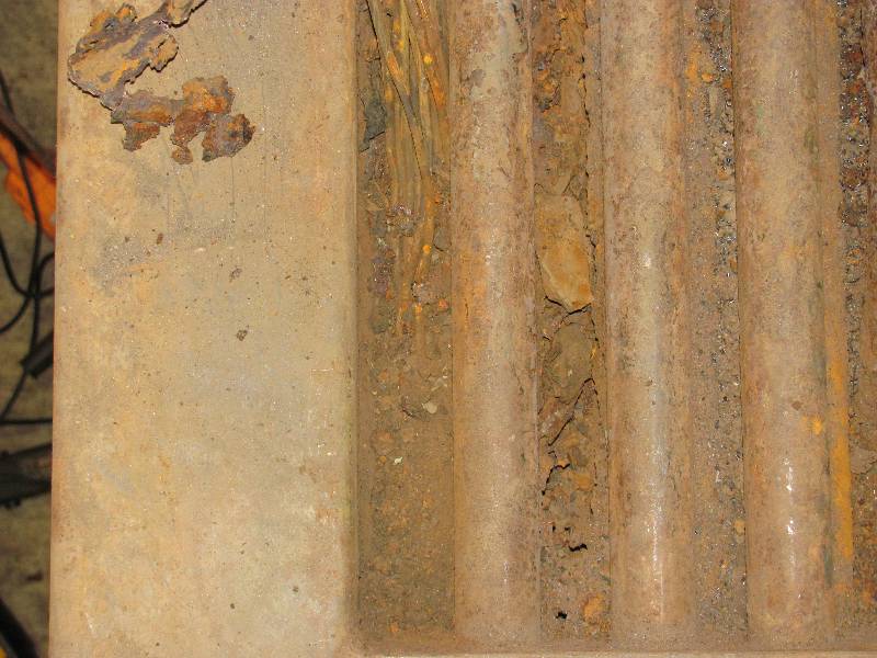
Work continues on the cable runs located under the fireman's side walkway. After looking closely at the situation and examining the alternatives, I decided that the only reasonable thing to do is to remove all of the rotten metal pipes and replace them with PVC pipe. Two of the boxes are completely rotted out and will be replaced. All 41 of the wires were numbered, cut at the rearmost box and then pulled out through the box closest to the cab. It turned out that many of the wires had bare spots in the insulation and will have to be repaired or replaced.
 |
 |
 |
 |
 |
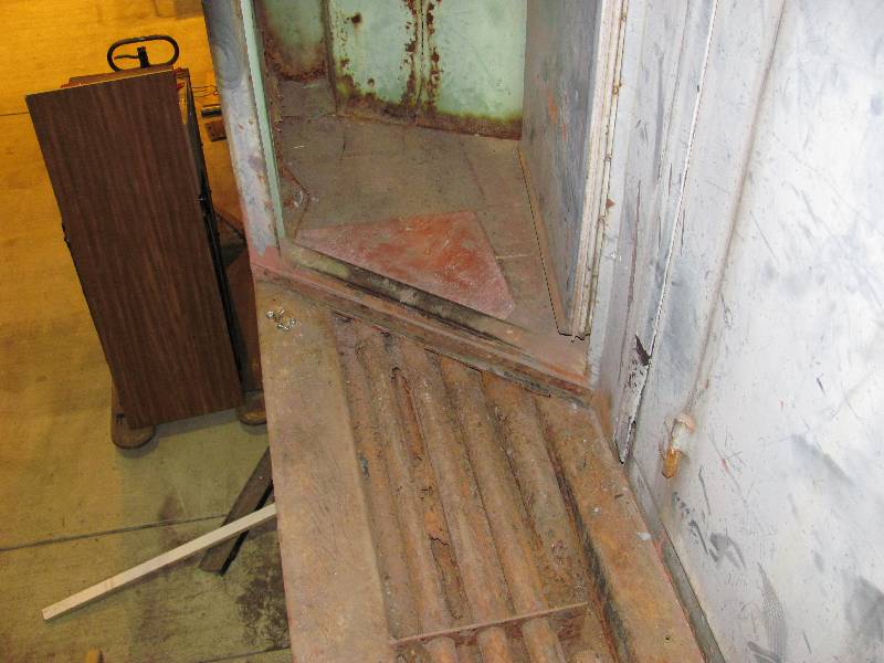
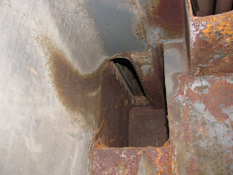
It was necessary to cut away part of the door sill in order to get access to the pipes. The conduit containing the wires was in horrible shape and was so full of rust that I could not pull the wires out. I had to number and cut the wires under the cab floor in order to get them one at a time.
 |
 |
 |
 |
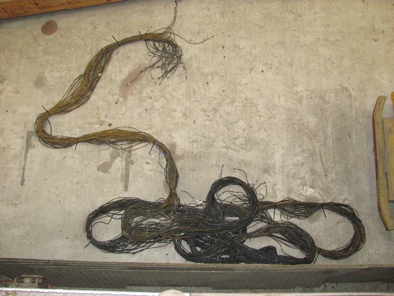
The fun went on and on getting the wires out. I found that the copper was rotten in many of the 40 foot long wires so they all will have to be replaced. Many are so deteriorated that a gentle pull would cause the wire to break. The wire bundle now occupies a shelf in the project storage area while work begins cleaning out the rotten pipe in the cable duct.
 |
 |
-- Update December 18, 2010 --
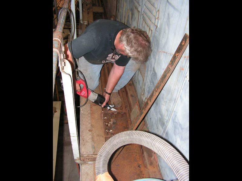
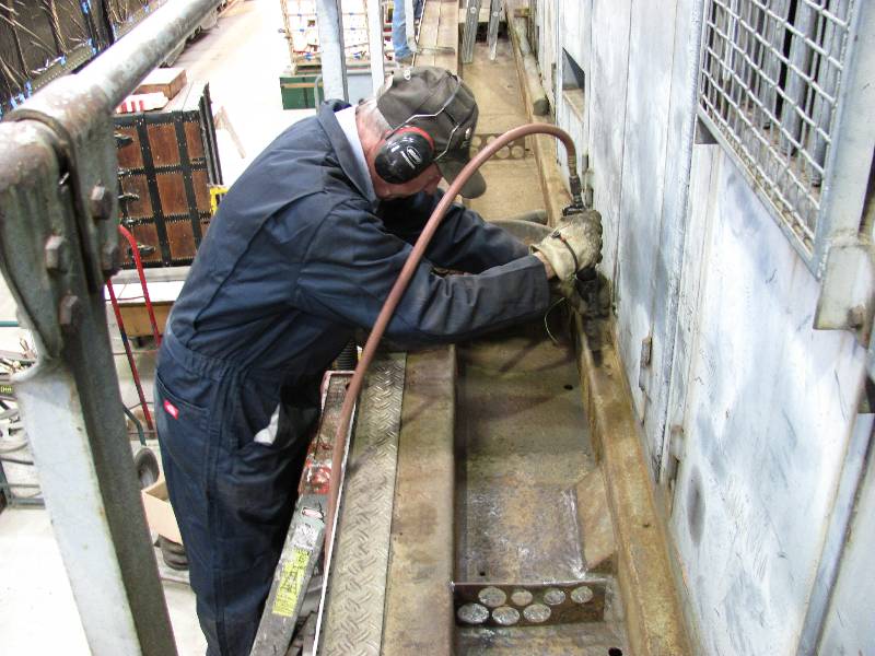
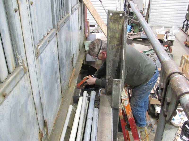
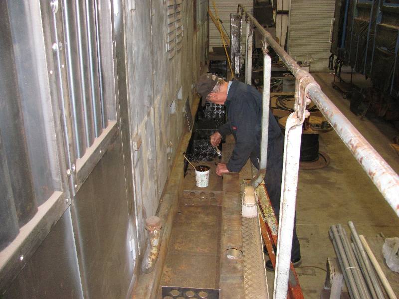
Mike dug into the nasty task of removing all the rotten pipe and cleaning out the channel while Rich pursued the unenviable task of needle gunning the rusty crap out of the channel.
 |
 |
 |
 |
-- Update February 24, 2011 --
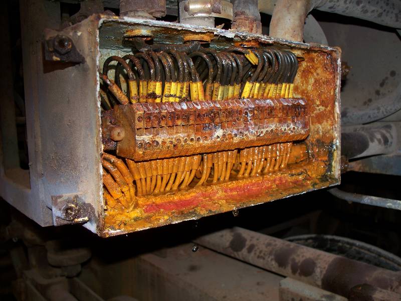
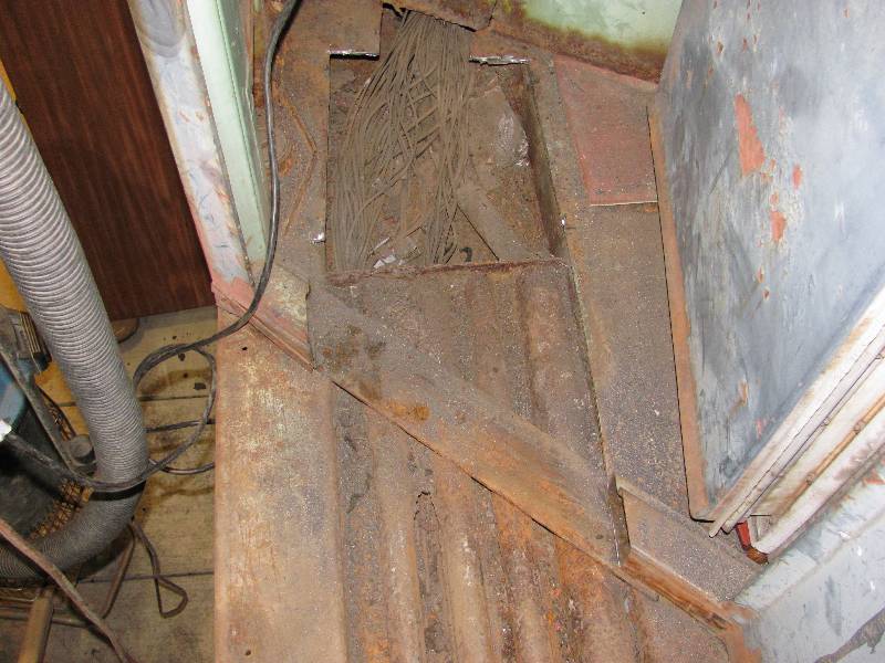
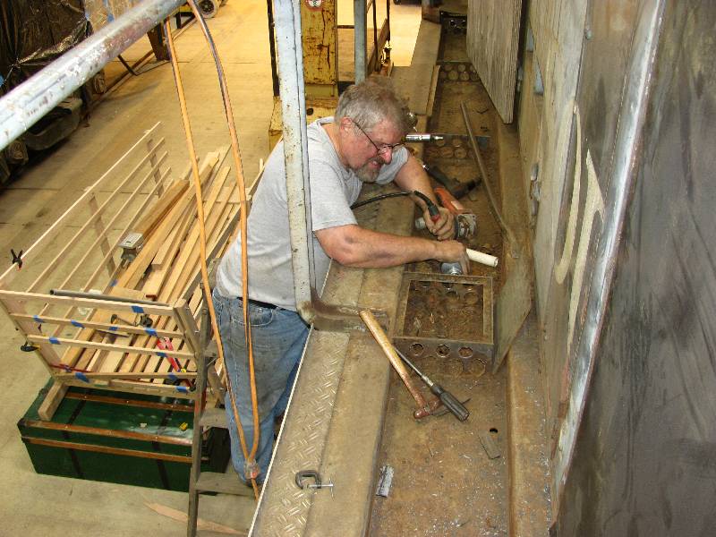
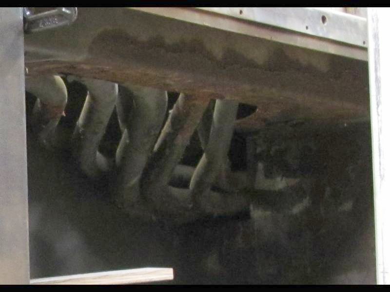
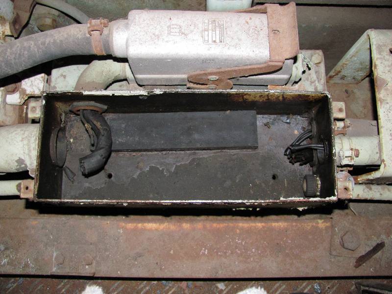
At the rear end of the frame, the wiring exits the last channel box, enters a set of tubes of various sizes which curve under the frame and up into the bottom of a junction box. We discovered that several of the tubes were completely rotted away and so they were all removed. We have decided to come up with some other system of routing the wiring into the junction box as replacing the tubes in kind would be too expensive and not of any cosmetic value. Mike created a system that will guide the cables up into the junction box and is seen here finishing the metalwork. And Rich is applying a coating designed for the inside of water tanks. We figure that the trough has rusted enough over the past 4 7 years.
 |
 |
 |
 |
 |
 |
-- Update April 03, 2011 --
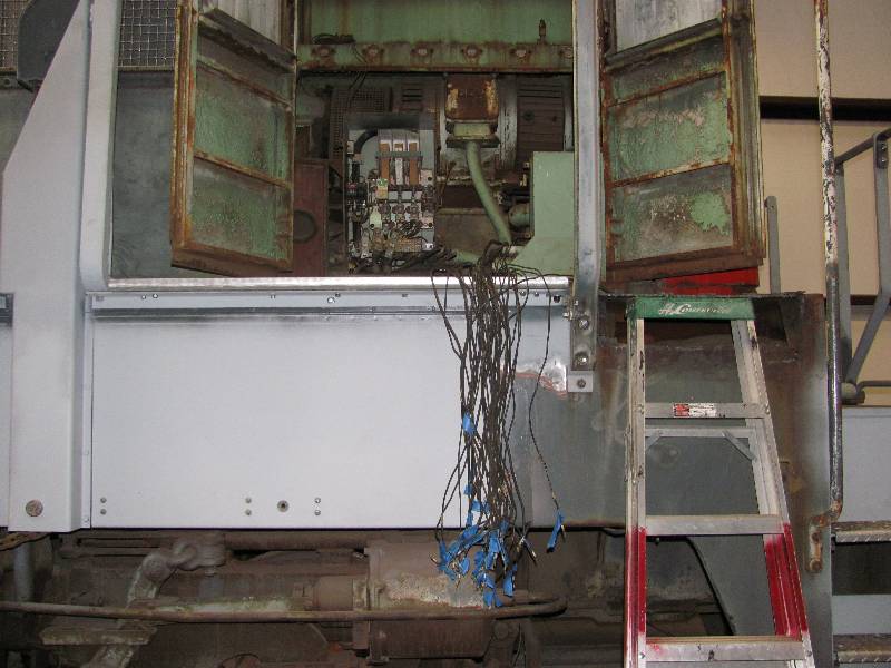
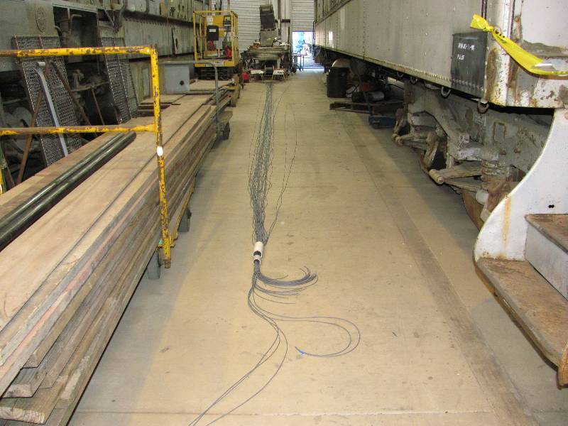
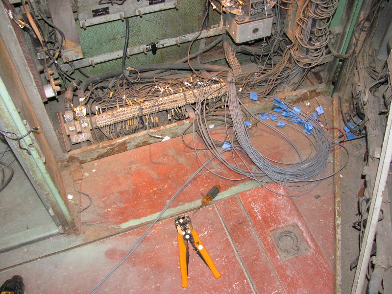
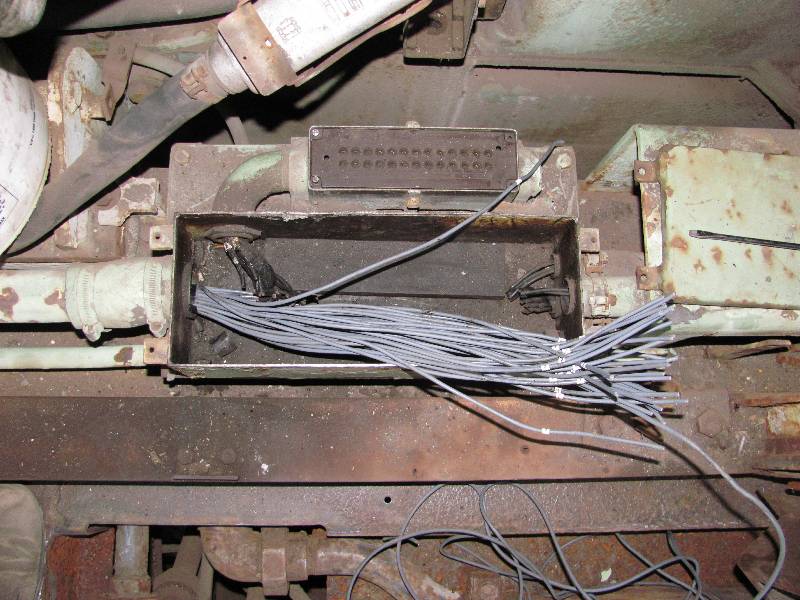
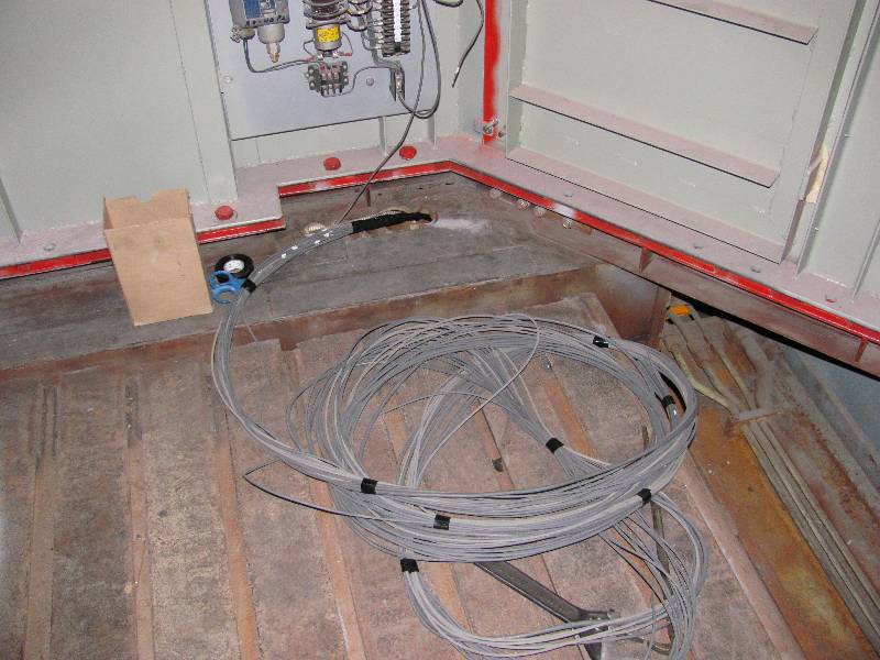
Mike has finished the installation of the replacement conduit and we have begun the arduous process of ringing out the 41 wires that were removed 5 months ago. The wires were marked end to end but there was no way to tell what each wire was for. So, in order to create documentation of the rewiring, we have to identify each one. It is not difficult, just very time consuming. By the way, the wires seen hanging out in photo #3 are only those for the rear MU and the rear lights. There are about 100 more needed for rear engine and transmission control.
 |
 |
 |
 |
-- Update June 01, 2011 --
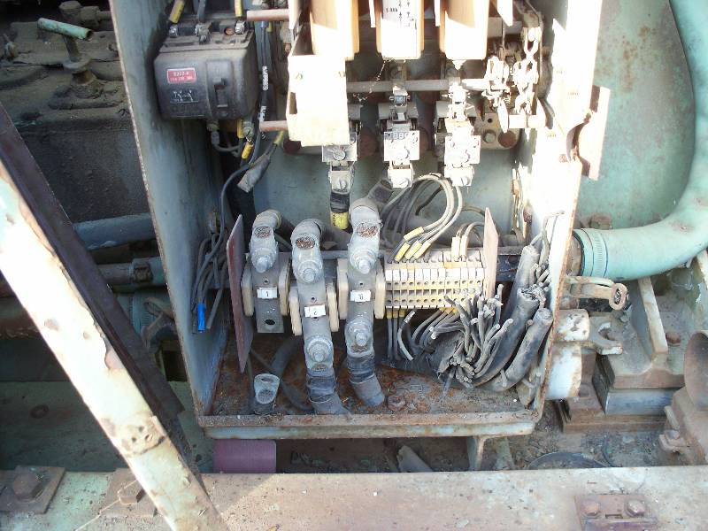
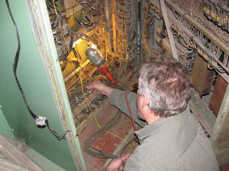
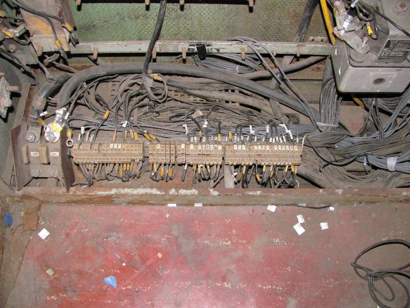
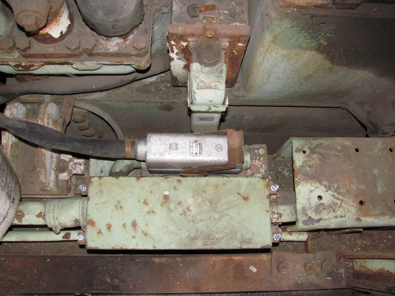
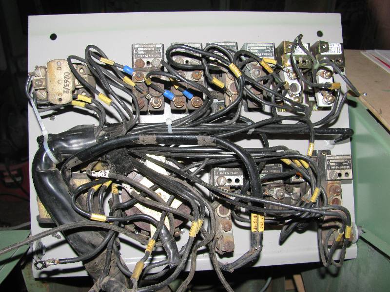
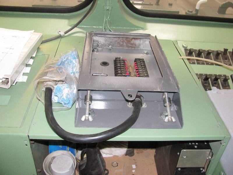
Surprises continue to turn up in the wiring. There are a pair of plugs and sockets on each engine that are used to connect various signals to the engine but allow easy disconnection should it become necessary to remove an engine. Photo 2 shows the main plug/socket on the #2 engine. One of the many circuits in the plug/socket consists of 2 wires that connect to the "engine governor solenoid". This device is attached to the back of the block, near the governor and is used to shut the engine down or allow it to run. If current is applied to the solenoid, the governor will be free to operate in the running mode. I have been working on wiring the starting circuits (because I want to get the engine prelube pump to run) and found that one of the wires to the solenoid could not be found among the cut off wires in the rear circuit breaker box (photo 3). I decided to open the box upon which the engine control plug and socket is mounted and found seriously fewer wires than I expected (photo 4). I then took the socket apart and found 13 wires attached to the socket but only 6 wires in the plug. Plus, I noted that the wires in the plug are not original Krauss Maffei wire but rather the type of wire that the SP used during the locomotives life. One of the engine governor solenoid (SGS) wires ran as expected from the solenoid directly to the plug. The other wire however was a surprise. It had been cut and attached to a wire that goes to the front of the block. Tracing this wire led me to a pressure switch mounted on the front of the engine. The wire was attached to one terminal of a normally open micro switch. The other terminal ran back down the block and attached to the plug on the SGS pin. What the heck was this switch for? Unfortunately, the hose attached to the pressure switch goes nowhere (on either engine) but it is in a position that suggests it could have been either oil pressure or fuel pressure. This arrangement means that the engine could not start unless the pressure on the switch was up to some point and that the engine would die if the pressure fell below some point. Since the engine is protected from low oil pressure already, the best guess is that the switch was activated by fuel pressure although that really makes little sense. Regardless, I put the wiring back the way Krauss Maffei intended and the SGS worked perfectly.
The same micro switch in the pressure switch led to another surprise. The wires in the locomotive are tagged with a number that can be looked up on the Krauss Maffei drawings. The micro switch has 2 sections, one normally open (for the SGS) and one normally closed to which were attached wires labeled with the numbers that were assigned to one of the temperature gauges in the cab. Wow, that was a surprise. Perhaps future exploration will reveal what this switch was used to activate but there is no way it could properly operate a meter. And then I remembered that the gauge panel had several gauges removed and the holes plugged (photo 5). It turns out that one of the plugged holes belonged to the gauge that the mystery wires used to power.
The Southern Pacific made some really serious modification to the locomotive's wiring during its life for which we have no documentation. It is possible to figure out some of them as we go, but I have concluded that as far as possible, the wiring will be put back as Krauss Maffei built it.
 |
|
 |
 |
-- Update August 12, 2011 --
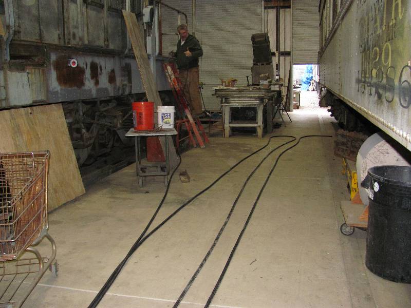
The large cables seen on the floor are those that connect between the start contactor in the cab and the Dynastarter mounted on the rear transmission. The smaller wires in the next photo are those that will reconnect the rear MU and lights. We elected to leave the end part of the rear MU wiring alone as is was in good condition and removing it from the conduit in the body would have been a real chore - not to mention replacing it. An area was created at the rear where the new and old MU wires could be spliced and protected against the elements.
 |
 |
 |
 |
And
then came the process of connecting the wires in the electrical
cabinet. Once done, it was time to check each of the 27 MU
wires
front and rear. The easiest way to do this was by connecting
a
bell between pin 4 (battery negative) and another pin and
then
operating whatever function caused the pin to receive voltage.
It
is a very simple and effective way to test continuity.
 |
 |
 |
As mentioned before, during Camera
Car conversion, the SP removed every last bit of wiring that was not
required for the new life. All told, there were over 100
pieces of #14 wire removed from the conduits that run from the cab to
the rear end. Among them are 31 wires that run to the right
side of the transmission and thence to a box where they are distributed
to the transmssion control plug, several temperature sensors and some
other functions. The wires come from a teminal box on the
left side and have to be connected at both ends.
Most of the wires that pass from left to right through the
box go to the temperature sensors which were connected in another
terminal box.
 |
 |
 |
 |
That
box was supported on a bracket which was
was clamped to the piping that let to the radiator spray water pump.
The pump had been removed which let the piping hang in mid
air so the bracket had to be redesigned.
 |
 |
 |
We also got one last spool of #14
wire and cut
another 41 pieces of wire to go from the cabinet in the cab to the rear
end. One more piece of 2/0 cable was also installed which
leaves
us no more wiring of this nature. The
fireman's side floor is back together and only needs to have
the floor panel welded in. That will wait a while - just in
case.
 |
 |
 |
 |
And now, we can turn our attention
to the lights on the newly installed short hood.
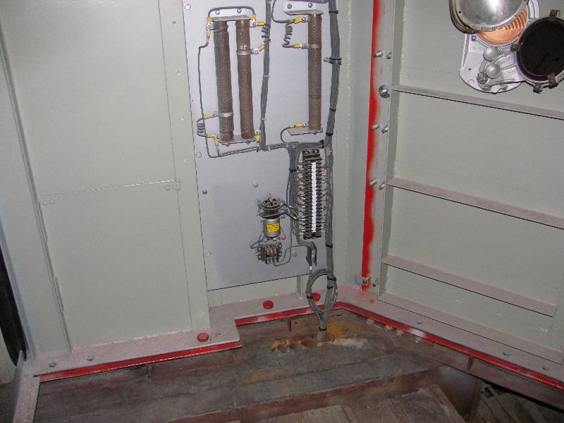
The wiring on the engineer's switch panel is a real rats nest
due to changes made for the camera car nose. Putting this all
back to Krauss Maffei's design was an interesting challenge.
 |
 |
 |
 |
 |
 |
--
Update July 08, 2013 --
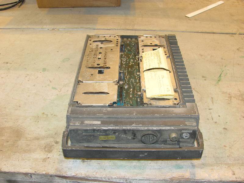
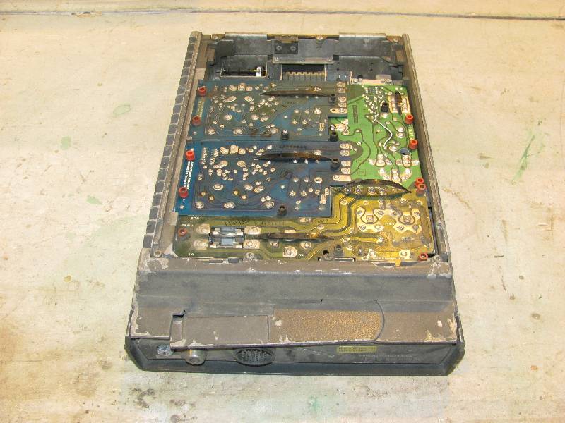
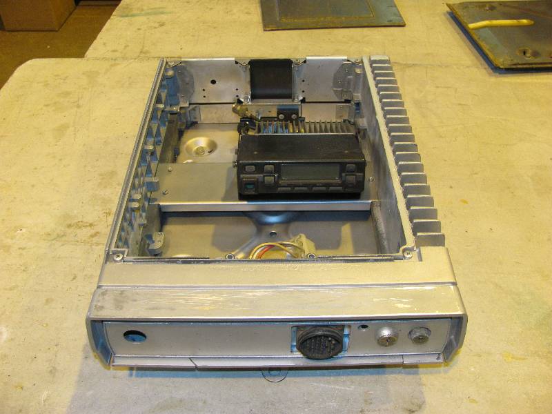
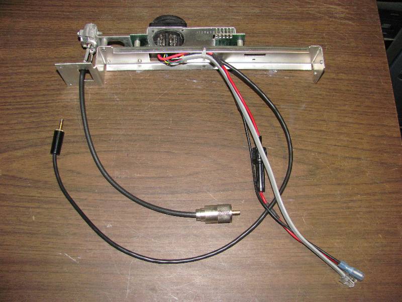
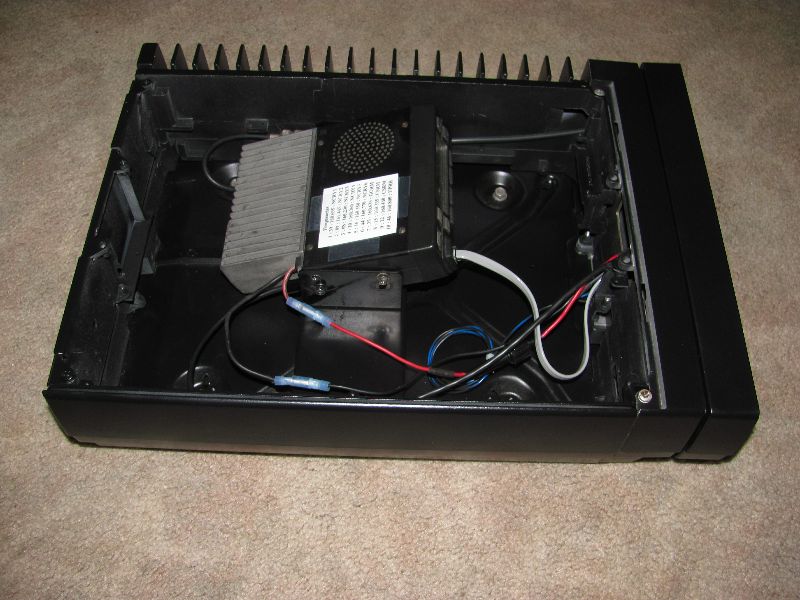
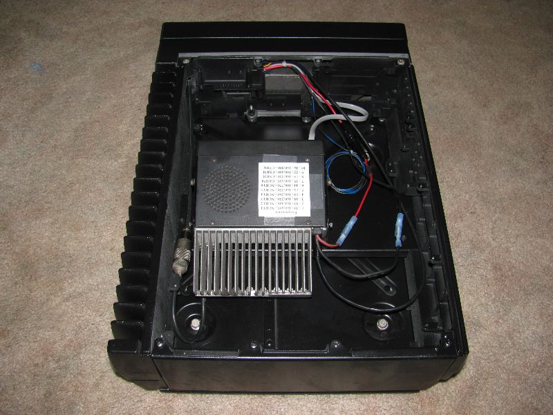
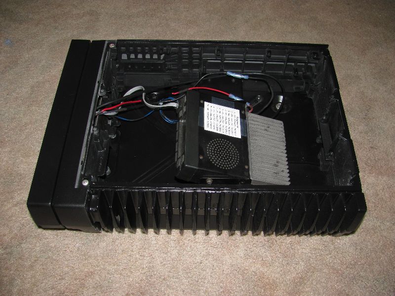
A project that has been going on in the background is the 2-way radio. The 9010 was equipped with a Motorola Micor 45 watt radio. These radios were used throughout the Southern Pacific and many other railroads. We would have simply installed an operating unit in the 9010 but for a change in the law that took effect in January, 2013. On that date, the frequencies that railroads used became subject to a "narrow band" ruling and since the Micor is not capable of narrow band operation, it had to be replaced. We wanted the Micor in the cab for cosmetic reasons so, I determined to hide a modern radio inside the Micor case. I gutted and bead blasted a Micor case and made a bracket upon which I mounted a Kenwood TK-760 transceiver. The Micor control head was also gutted and rewired to function with the Kenwood.
A project that has been going on in the background is the 2-way radio. The 9010 was equipped with a Motorola Micor 45 watt radio. These radios were used throughout the Southern Pacific and many other railroads. We would have simply installed an operating unit in the 9010 but for a change in the law that took effect in January, 2013. On that date, the frequencies that railroads used became subject to a "narrow band" ruling and since the Micor is not capable of narrow band operation, it had to be replaced. We wanted the Micor in the cab for cosmetic reasons so, I determined to hide a modern radio inside the Micor case. I gutted and bead blasted a Micor case and made a bracket upon which I mounted a Kenwood TK-760 transceiver. The Micor control head was also gutted and rewired to function with the Kenwood.
 |
 |
 |
 |
 |
 |
 |
 |
 |
 |
 |
 |
Return To Main Page