Southern Pacific
9010
Front End Work
Page 2
--
Update January 25, 2010 --
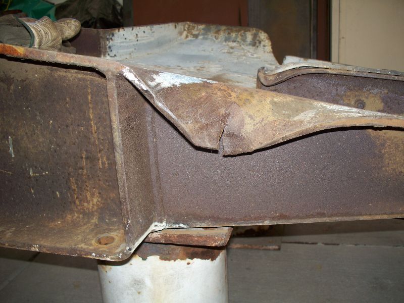
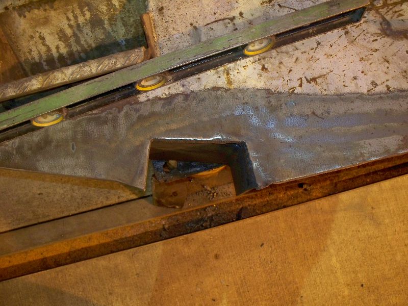
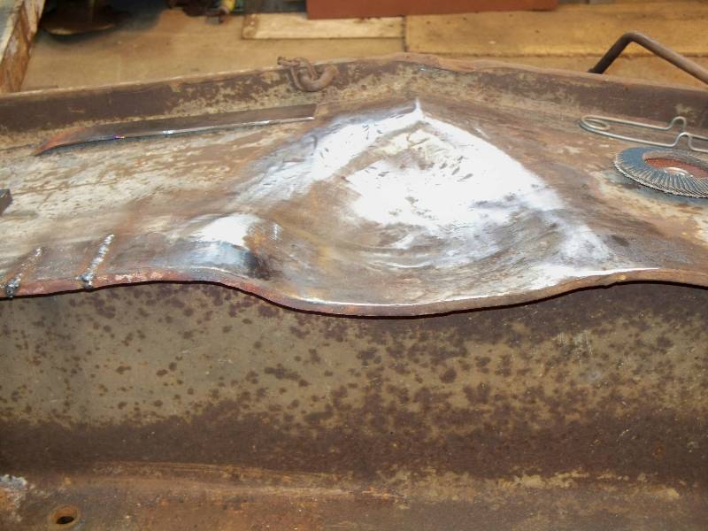
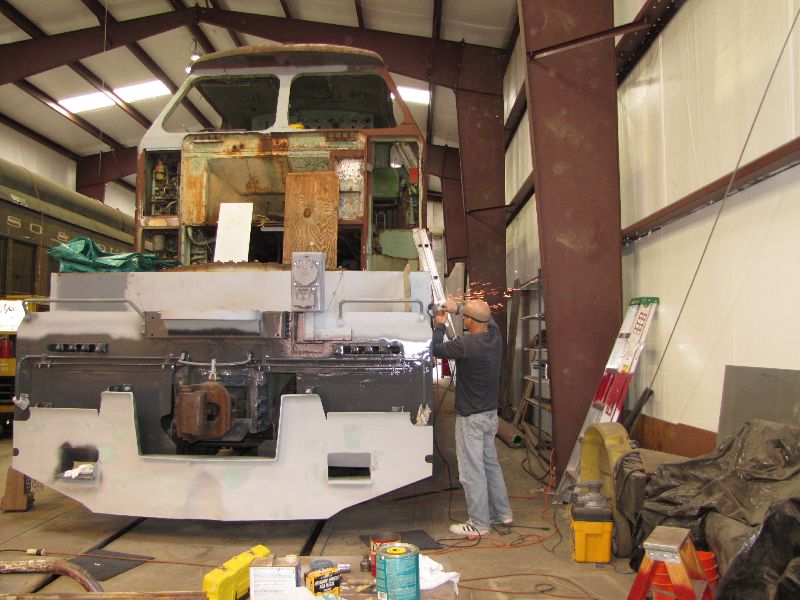
There
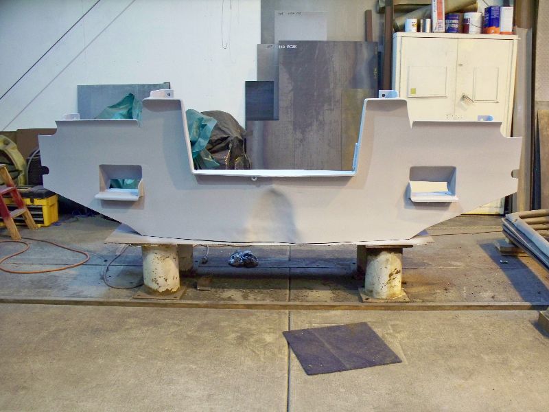
are 4 major areas needing repair on the pilot. The two rips
in
the bottom edge were caused by running the locomotive into wheels stops
which were firmly attached to the end of storage tracks.
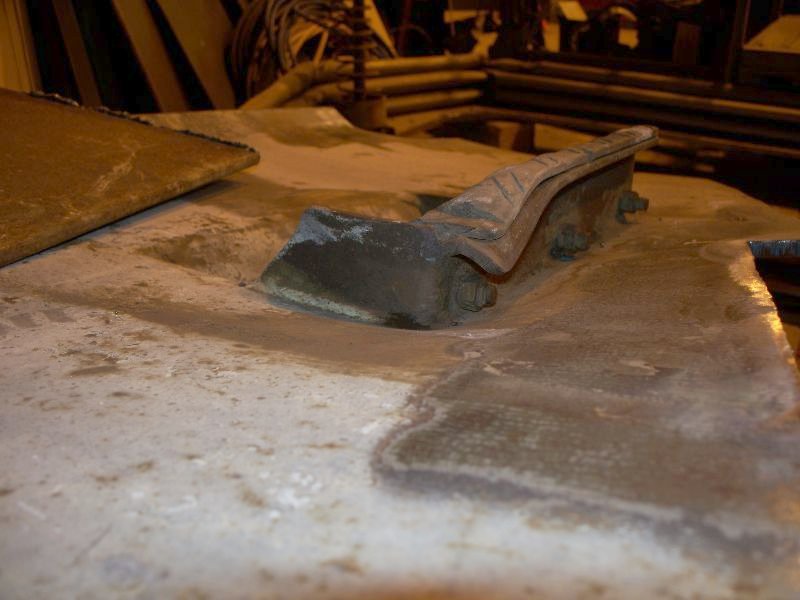
The bends in the center and the bend in the step were caused
by
the common event of striking something hard between the rails.
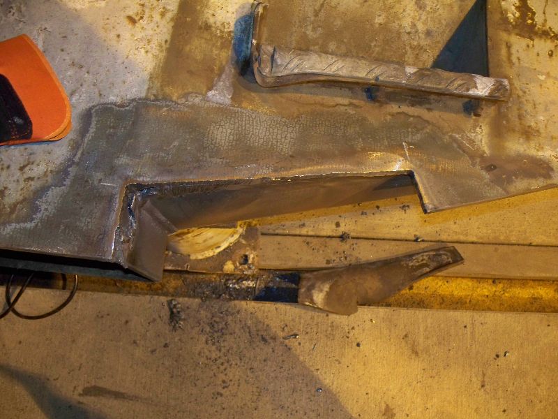
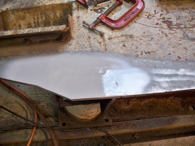
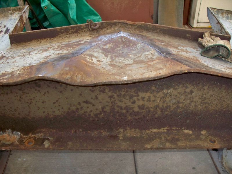
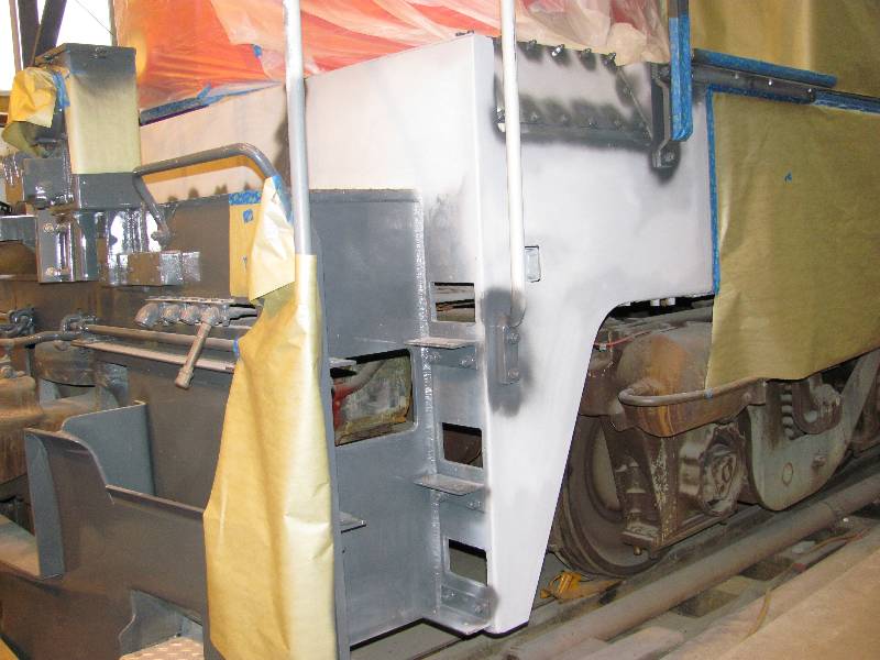
Liberal applications of cutting,
forming, welding, heating, jacking and banging brought the pilot back
to a
presentable condition. Oh, and that center "divot" is not a
dent,
like we first thought. It is actually a clearance that KM
applied
to the entire second batch, 9010 - 9017. It took some
sleuthing
to discover that 9010's plow was actually banged up by design!
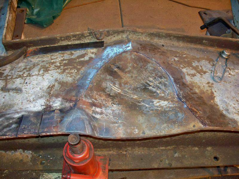
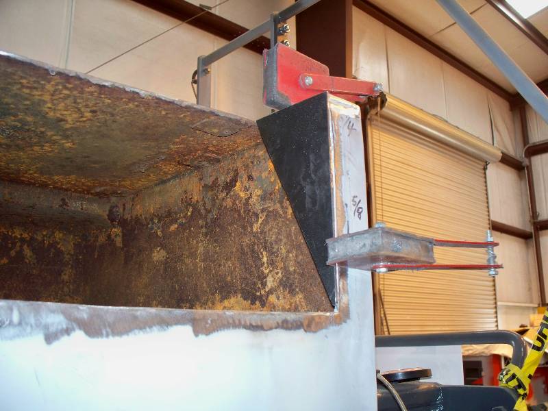
The rips -
-
the "divot" -
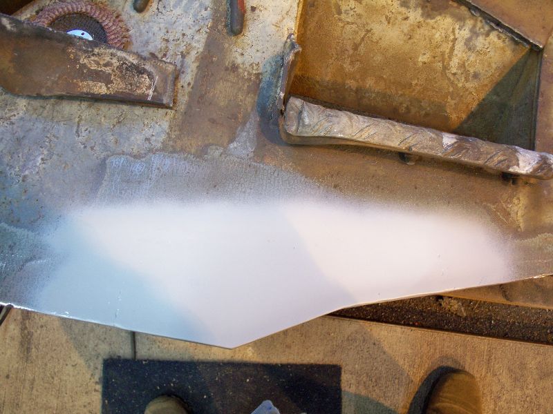
- the step -
-
and the pilot, almost ready to paint.
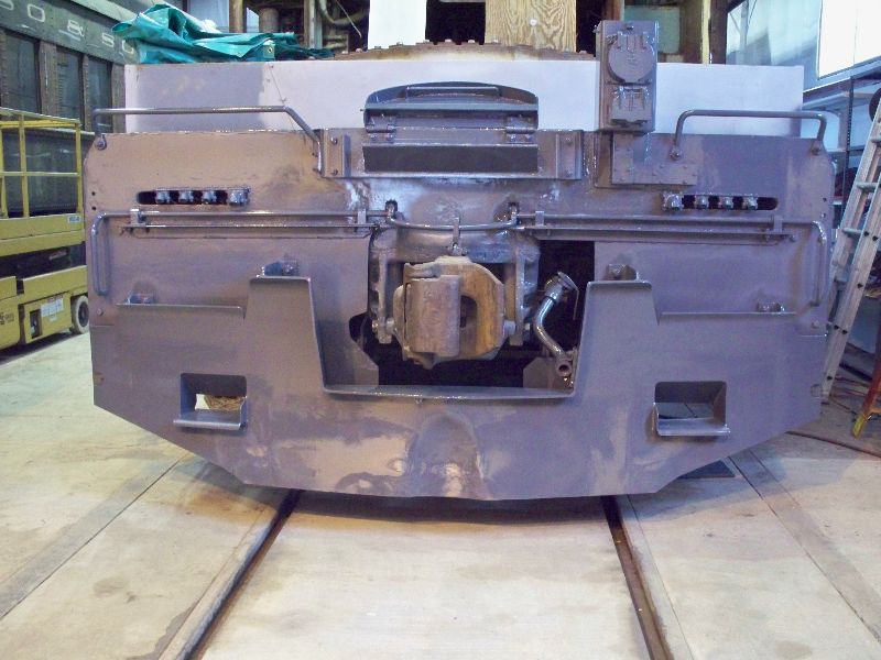
Some
may ask, "why didn't you fix the bends at the center bottom of the
pilot?" My answer is that we are representing the 9010 at a
day
in its service life, not the day it came off the ship. If we
were
making it look brand new, many other defects such as the welded patches
in the fuel tank would also have to be repaired. The 9010 is,
after all, a used locomotive.
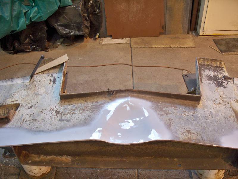
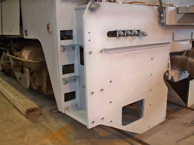
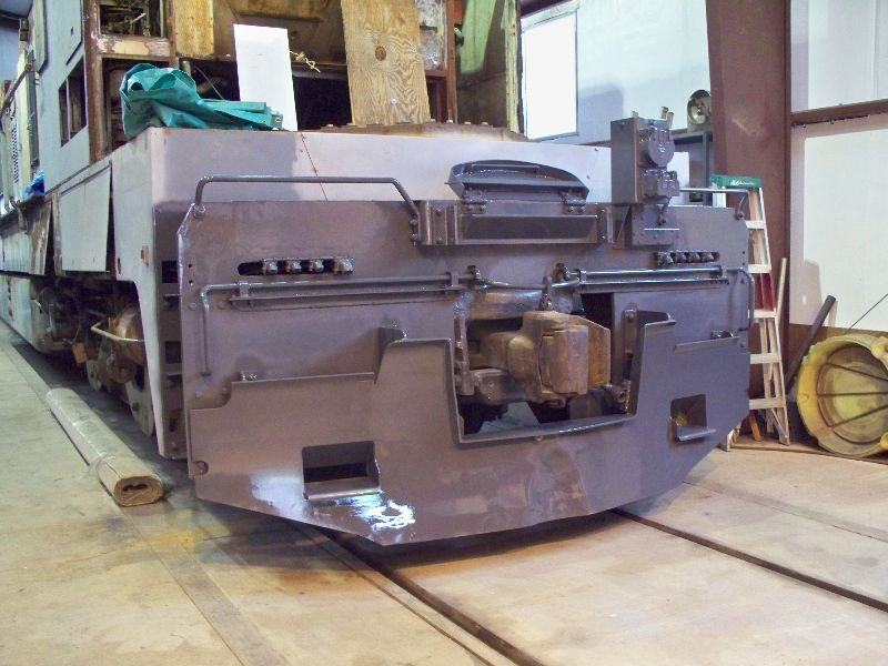
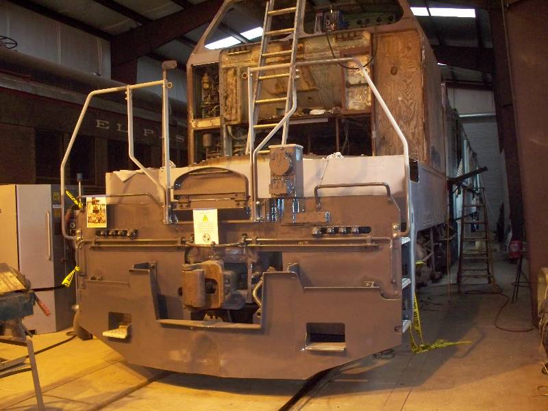
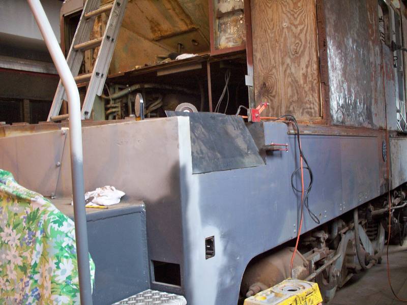
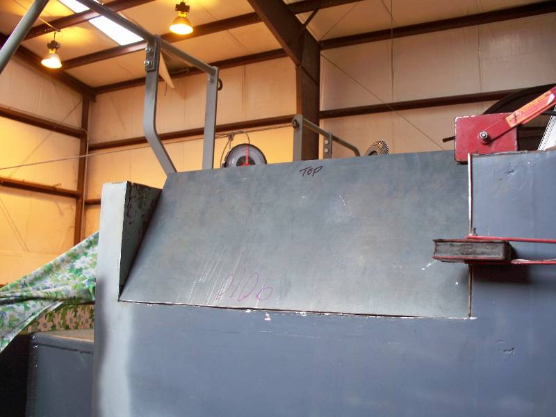
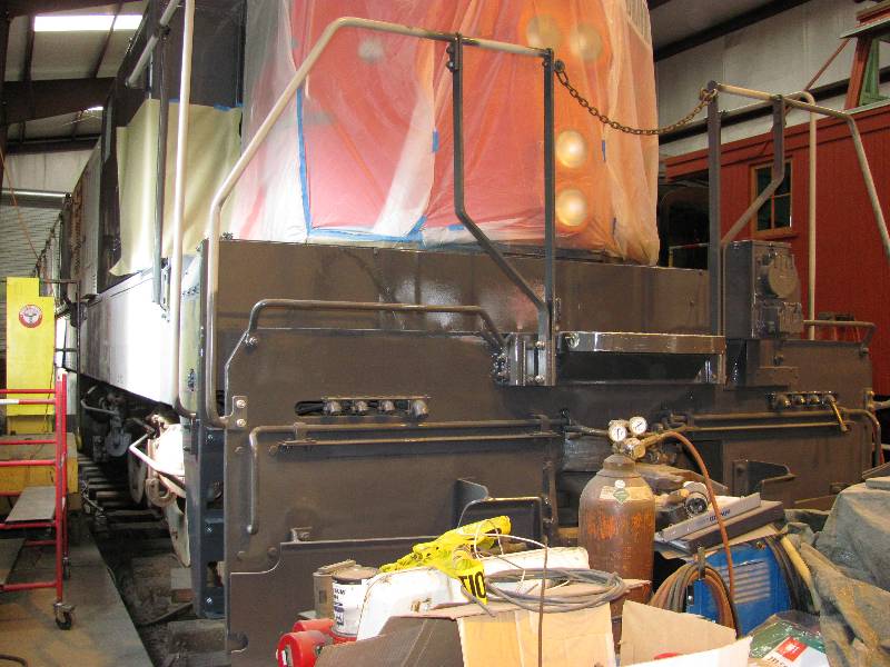
In
addition to the work above, the front end was given a coat of
epoxy
primer and then the lower part and the back side of the pilot were
painted with SP Dark Lark Gray so when the
pilot is
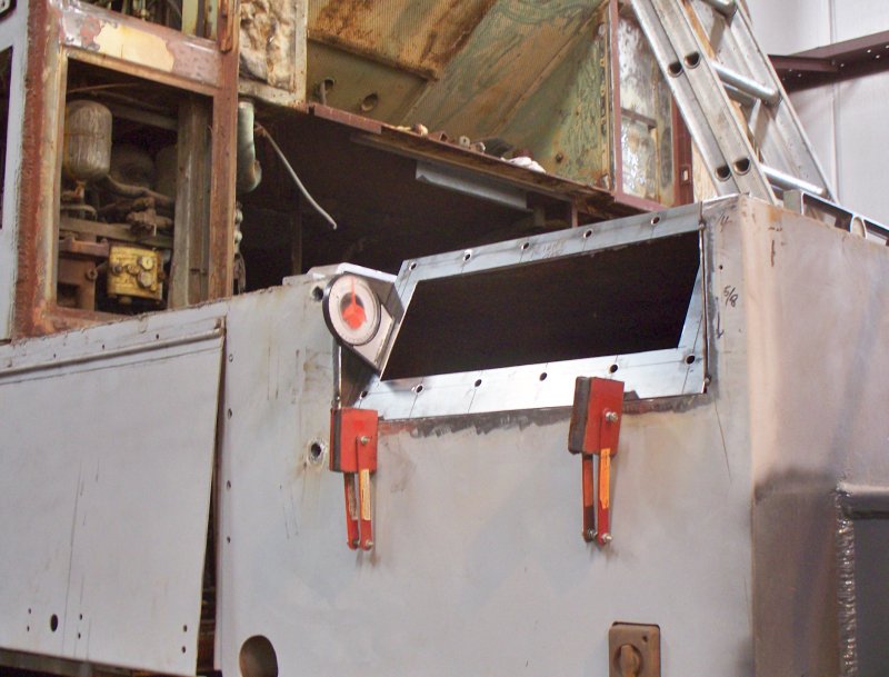
mounted, there will not be any unpainted areas. The cut
levers
were temporarily mounted to wooden brackets to allow painting the back
and underside of the assemblies. The paint is
a catalyzed polyurethane custom mixed to match a
Southern
Pacific color chip for Dark Lark Gray.
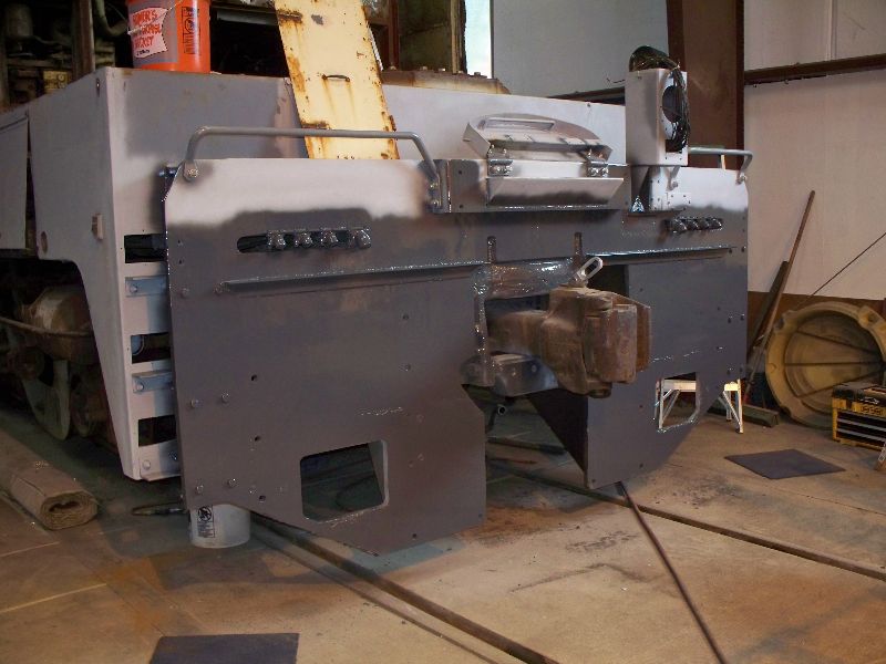
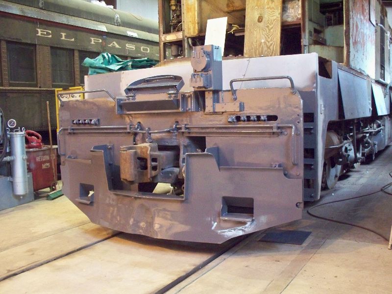
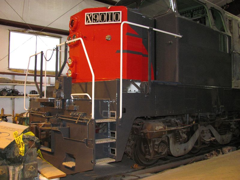
And
later that week, we finished the wiring to the MU box and
then mounted the the cut levers and the pilot to the front
end.
"Bondo Dan" Furtado came down to work his magic on some
scars on
the pilot and then the entire front end was given a coat of paint.
The front end and pilot will receive another coat when the
construction of the new hand rails is finished.
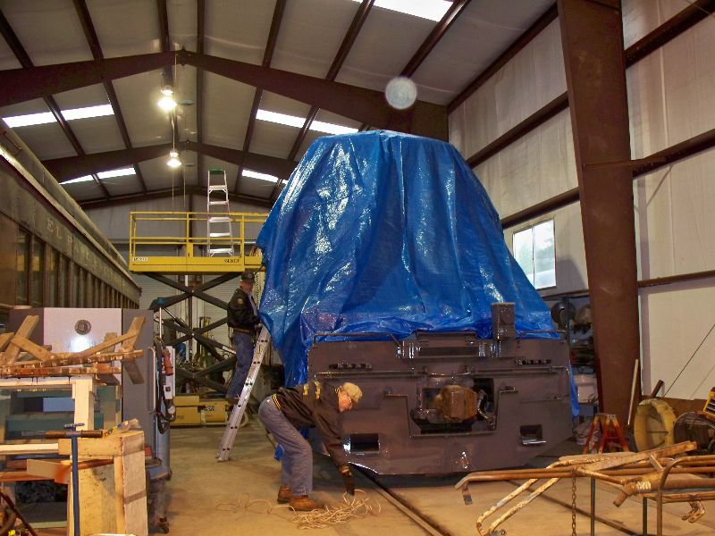
Unfortunately,
the 9010 has to leave the shop building for about
a month so the Steamies can work on some freight cars for an upcoming
event so work will start on the front end hand rails.
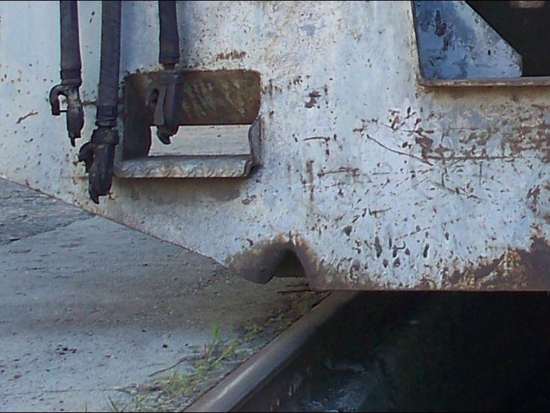
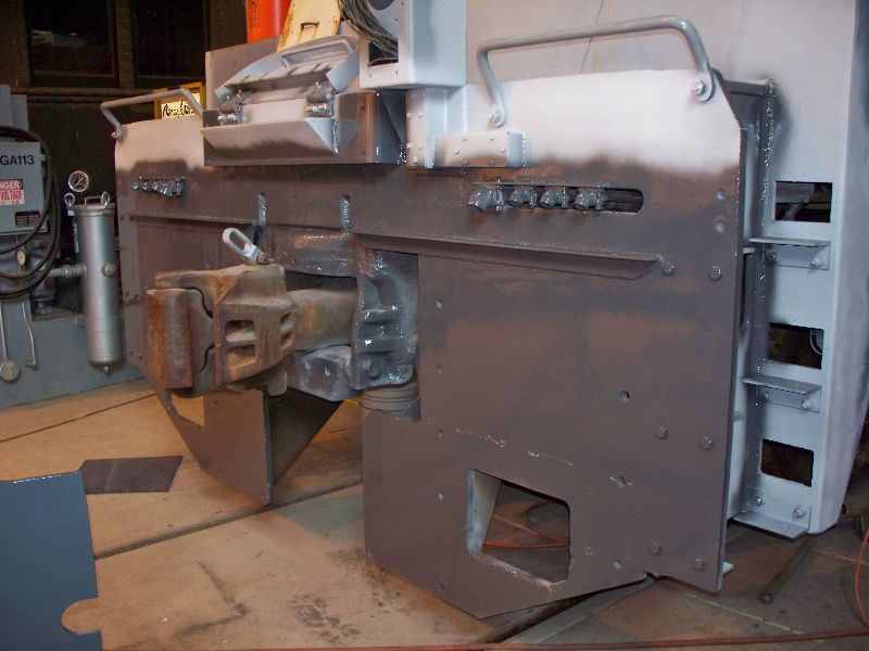
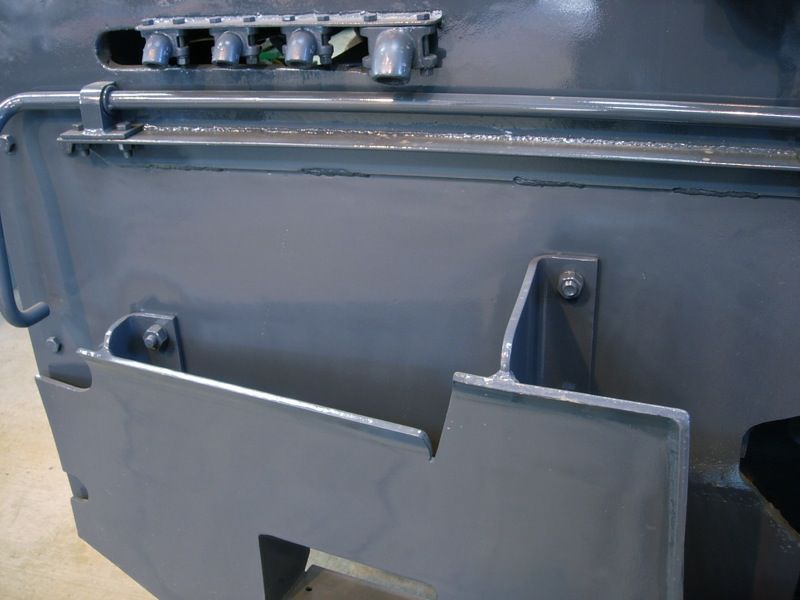
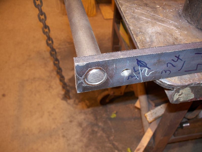
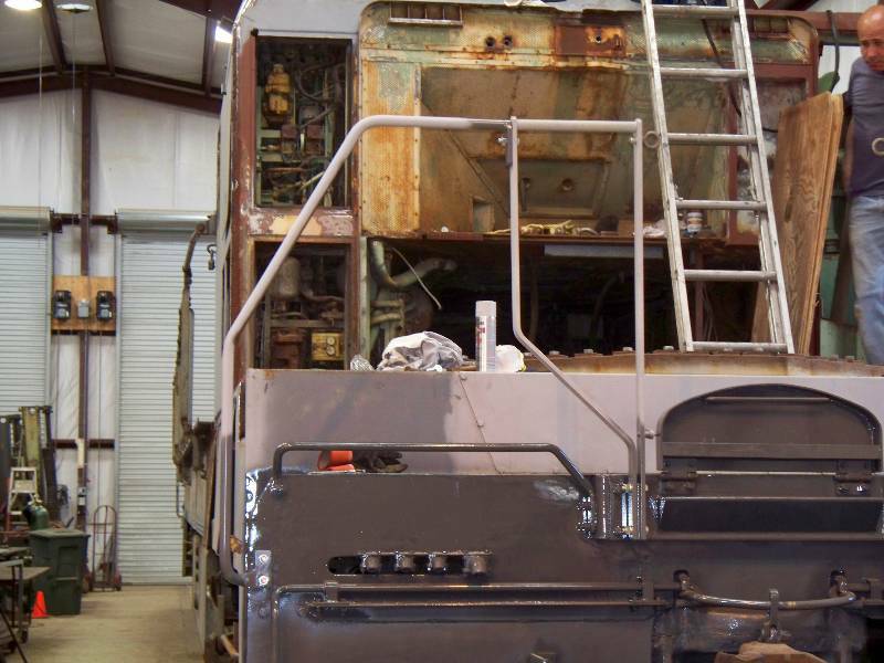
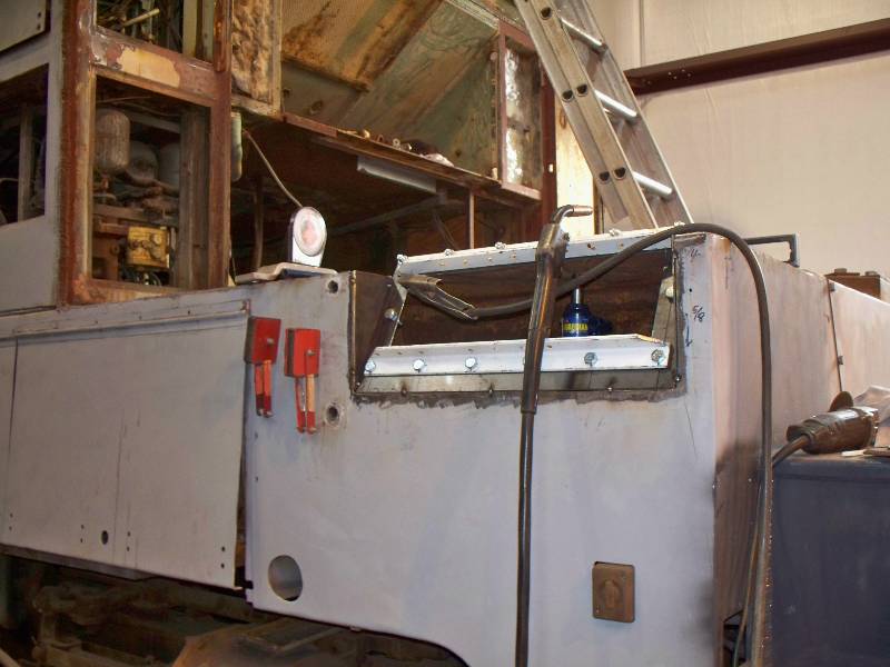
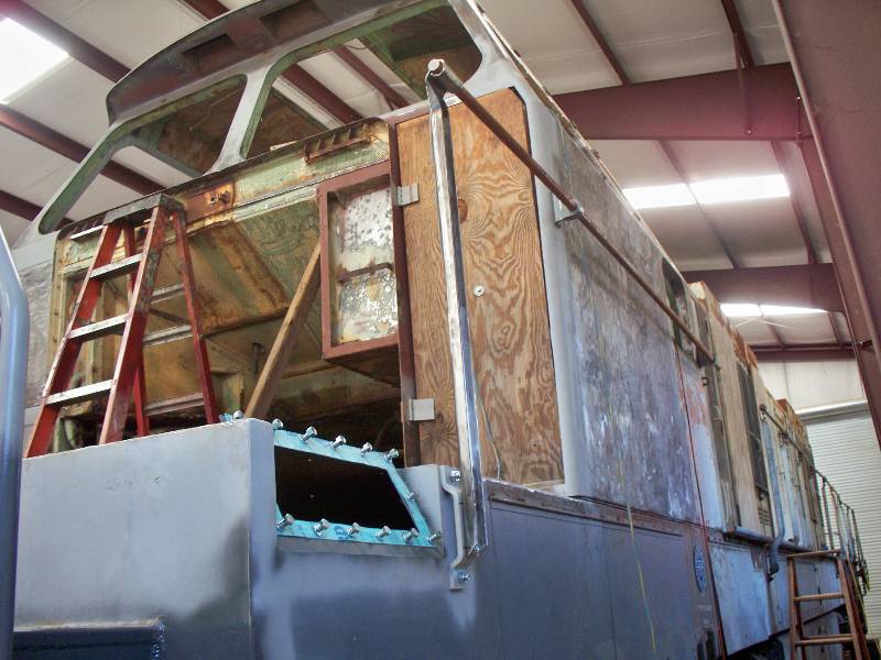
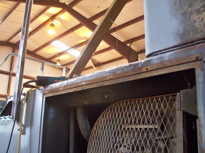
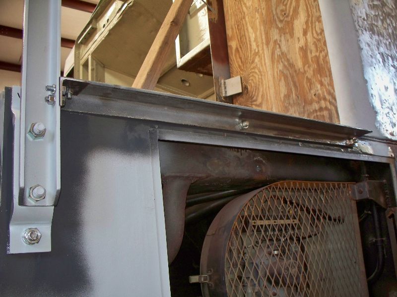
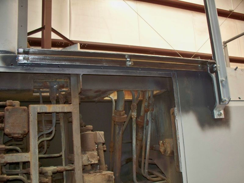
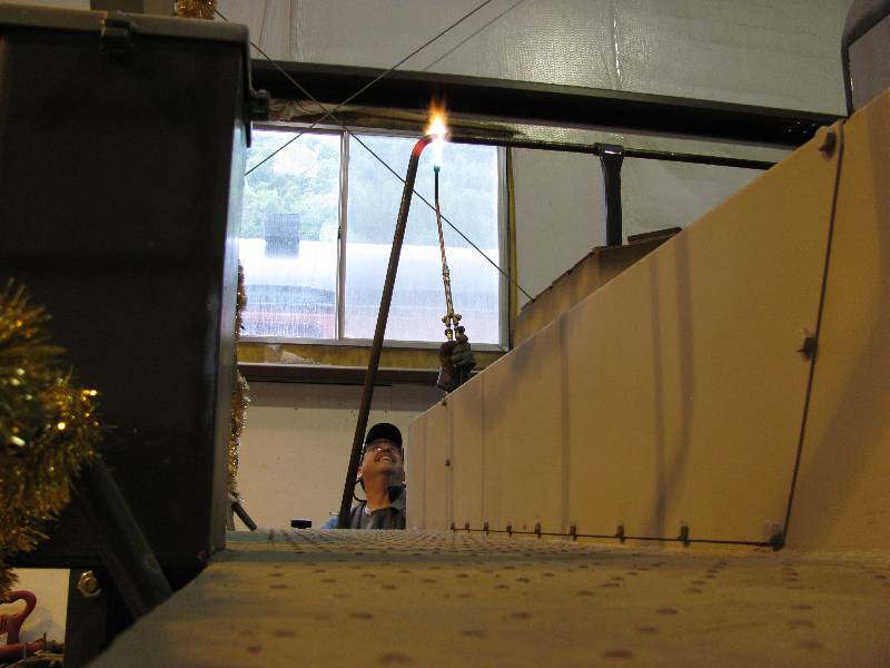
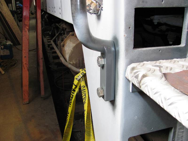
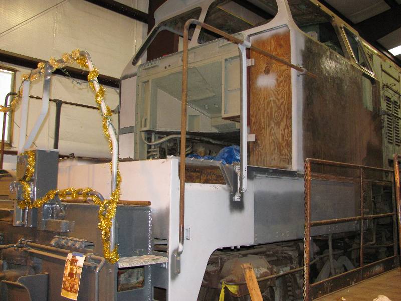
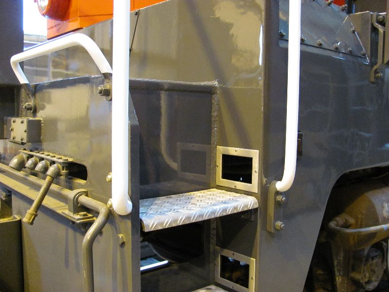
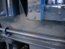
According
to visiting mad man Bob Zenk, "beauty is in the details". The
welding scars seen in photo 1 and 4 are a result of SP's very first
modification; the raising of the MU box. We decided to keep
them.
R J Zenk Photo
|

R J Zenk Photo
|

R J Zenk Photo
|

R J Zenk Photo
|
--
Update February 10, 2010 --
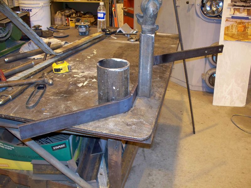
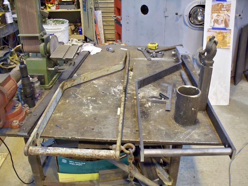
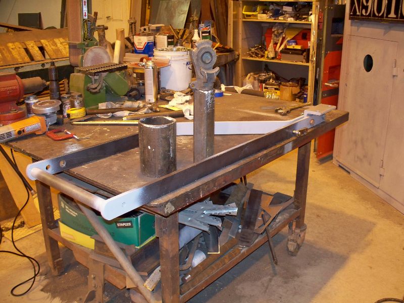
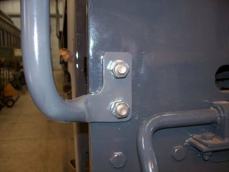
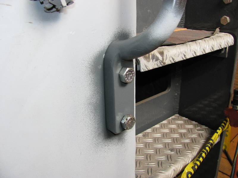
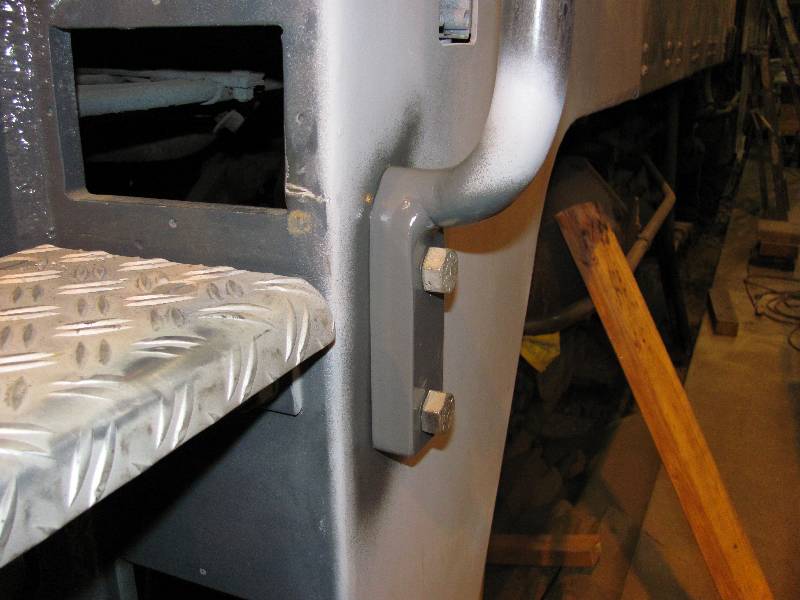
The
front hand rail assemblies are of interesting construction. A
short bar has its ends turned down slightly and inserted in holes in
the vertical members. The two are welded together and the
welded
joint is ground flush. There is a little heating and bending
involved in the assemblies but unfortunately, no banging (my favorite
part).
We removed the parts from the rear end to serve as patterns.
And now, we have a completed assembly which
includes the
little latch for the MU step.
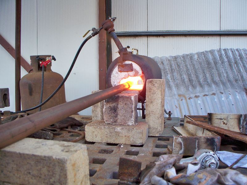
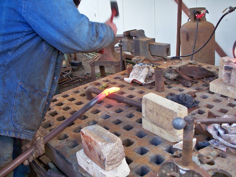
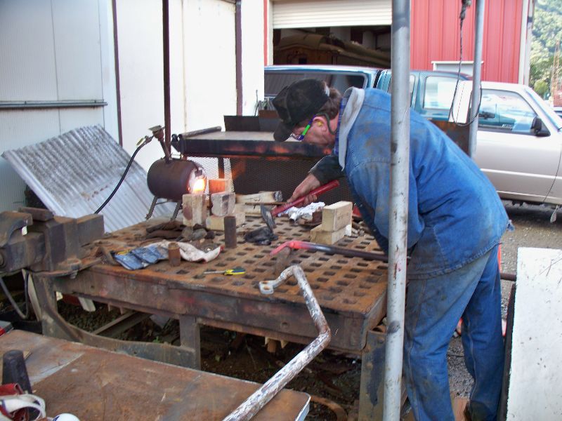
Our
blacksmith, Joe Man is working on forging the ends on the hand rails
that attach from the front end to the hand rail assemblies.
Watching him work the metal is a real treat.
With the locomotive outside for a while and the hand rail assemblies
completed, work will resume on the nose.
--
Update March 12, 2010 --
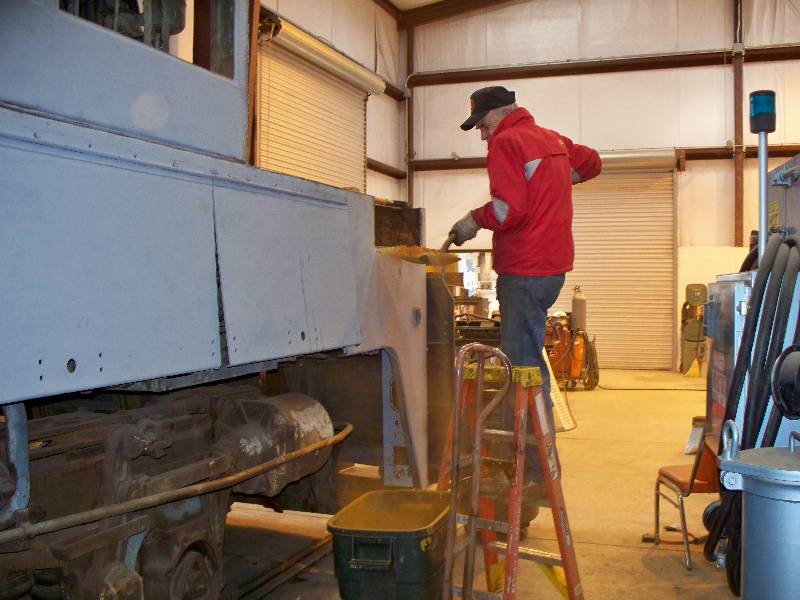
Once
back in the barn, Gerry turned his efforts toward cleaning out the
front sand
boxes. When they were plated over, the sand inside turned
into
something resembling a refrigerator experiment.
--
Update April 28, 2010 --
Our
attention turned to finishing the handrails that Joe Mann forged.
The compound bend at the bottom of the bars were a particularly
interesting challenge. With the installation of the other
hand
rail, reconstruction of the front end sheet is done. There
are a
few details like MU hoses and paint that will be added at a later date.
--
Update May 21, 2010 --
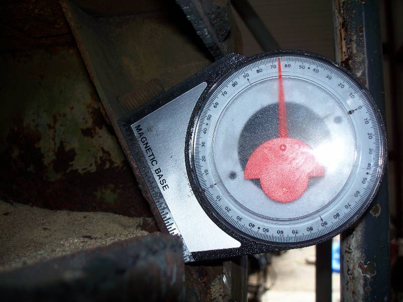
I
have been ignoring the two missing front sand box mounts for a long
time because their construction seemed complex and the condition of the
remaining metal was so bad. But, the day came when
I
decided to dig in and figure out what to do. Both front
boxes
had their mounting plates completely removed during camera car
conversion so there was no help there. I opened up the left
rear
box and found that the majority of the plate was intact, at least
enough for me to measure the angle of the plate which turned out to be
65 degrees. With that in mind and having opened up the two
front cavities, the work began by cutting out the rotten triangular
shaped pieces at
the ends of the openings. New pieces were
fabricated, tacked into place and then dimensions were taken
for the base plates which were cut and test fitted. Bob Zenk
had created a drawing showing dimensions of these plates which was a
tremendous help.
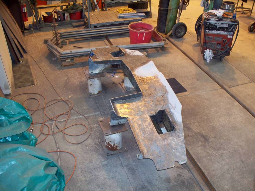
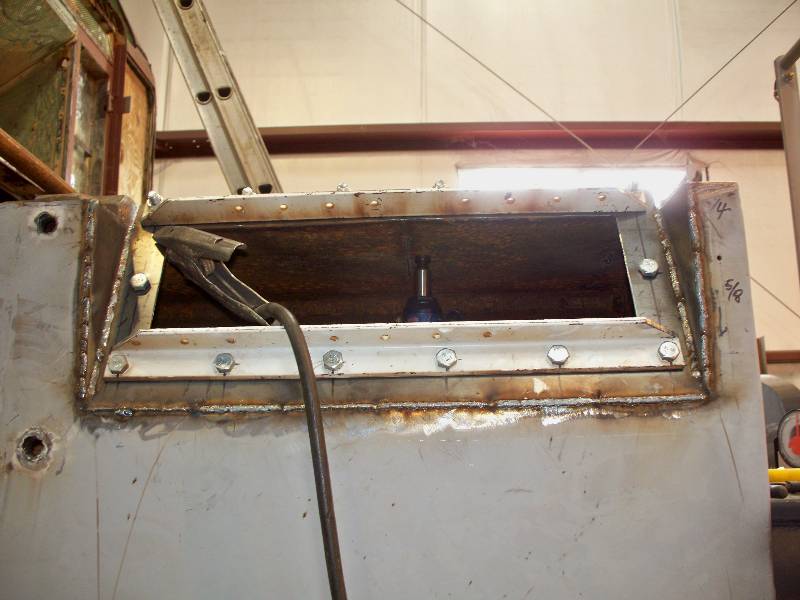
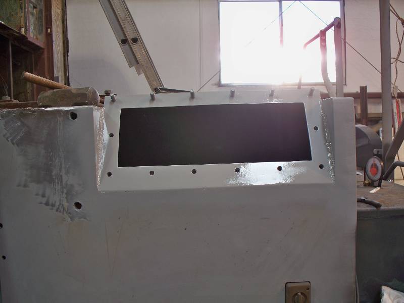
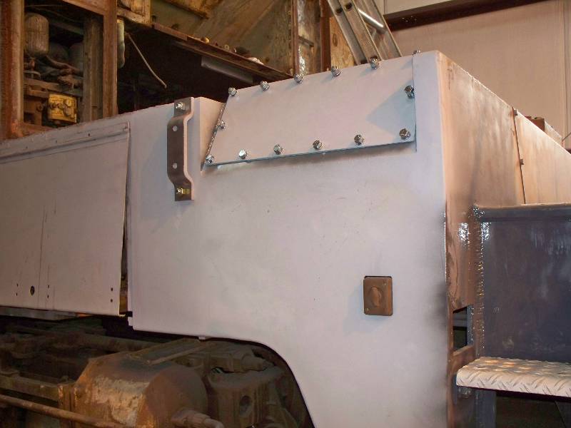
The
plates received their 28 - 1/2" holes and the central opening.
Plus, covers were cut and drilled. These
pieces will
serve to
cover the openings in the bases and will eventually be the mounting
flanges for the sand boxes. The angle iron shown in the
center 2
photos was bolted to the plate to keep it flat during the welding
process. Once that was completed,
these two boxes were as done as they could get for now. There
are
only 6 more to do - some day. As
it turned out, this was not too bad a job with a lot of cutting,
drilling and fitting but unfortunately, no hitting which is usually my
favorite part.
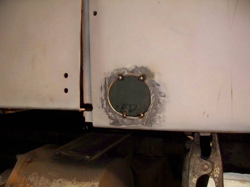
While
working on the right front corner, I welded a patch into the hole that
was left when the hand brake (relocated here by the SP in
1968)
was removed during Camera Car conversion. The newly formed
bracket to the left of the sand box lid is for a front side hand rail
stanchion.
--
Update July 03, 2010 --
There
has been work on the two missing front hand rails.
The first
order of business was to make replacements for the
two stanchions that support the railing. I removed
part of the
railing behind the cab and put the new bar through both of the supports
which allowed me to hang the stanchion from the bar. By doing
this, I was able to align the stanchion to the mounting bracket and
bend the top of the stanchion as required. The stanchions are
actually EMD parts that were lengthened for this application.
There will be more work on them once the end of the bars are
forged
to make the mounting pads that are bolted to the body next to the
steps.
I also worked on the extension angles
that will support the walkway extensions.
--
Update July 17, 2010 --
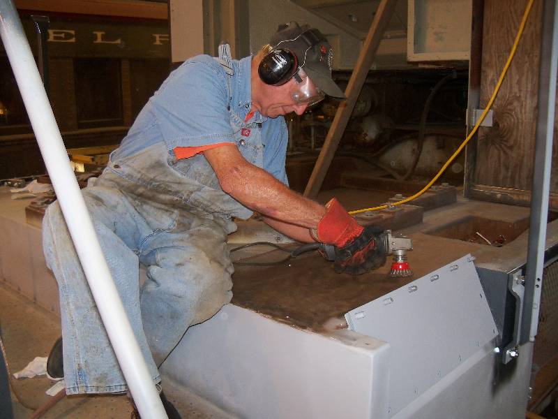
Rich
has been busy with
the cup brush cleaning all the metal surfaces on the front
deck. He then applied a coat of a rust converting chemical.
The surface is now ready for the new aluminum deck plates
which
have yet to be made.
--
Update November 28, 2010 --
Joe finished
the front end vertical hand rails. His talent
with forge and steel continues to amaze me.
--
Update February 01, 2011 --
We
finally managed to repair the left front pilot step that had a rather
nasty bash. Our machinist Bill located a product
called
"Alumiweld" which is much like brazing, only for aluminum.
With
some bending and hitting and Bill's application of the Alumiweld, the
step looks nearly like new and is back in place on the pilot.
--
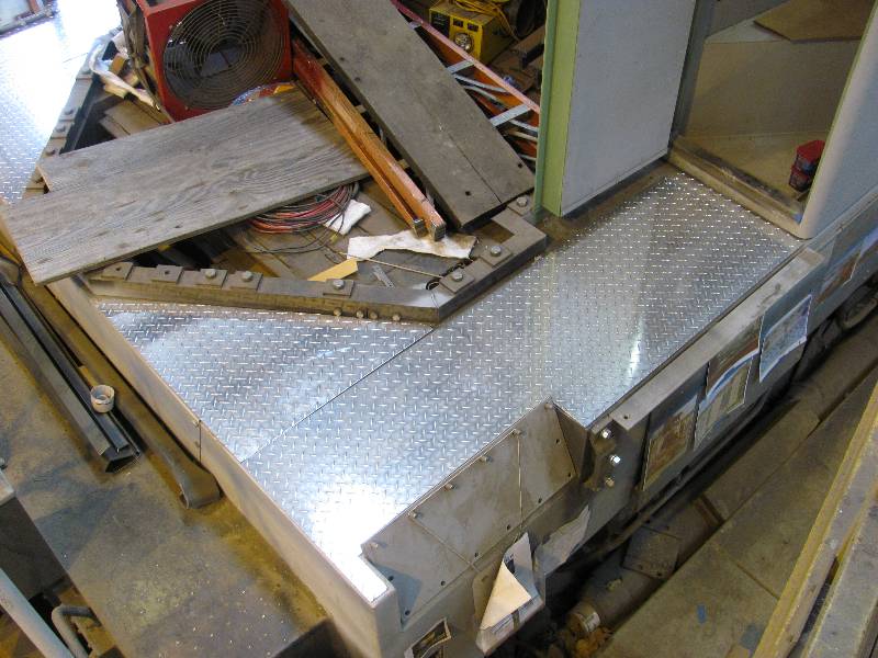
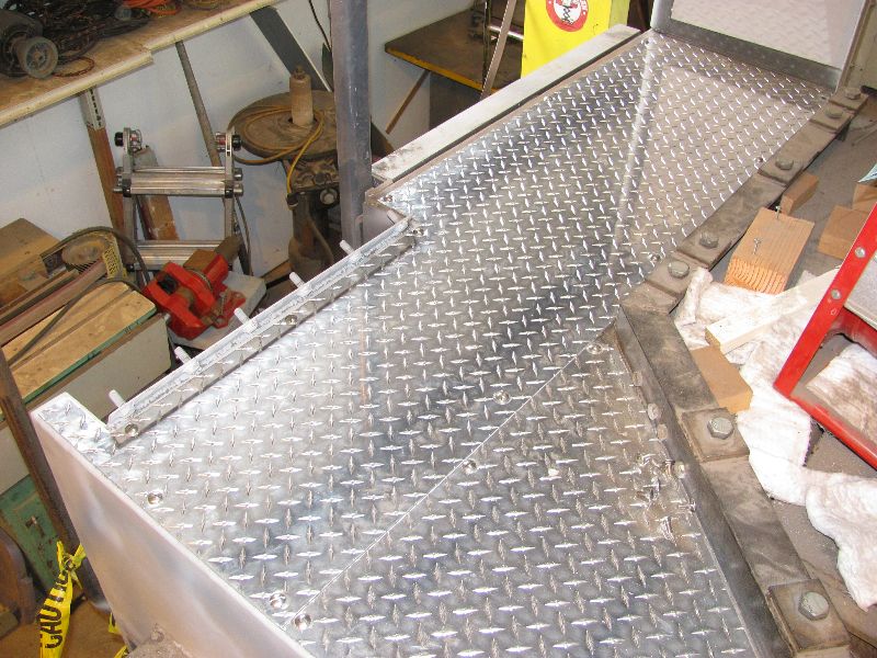
Update May 04, 2012 --
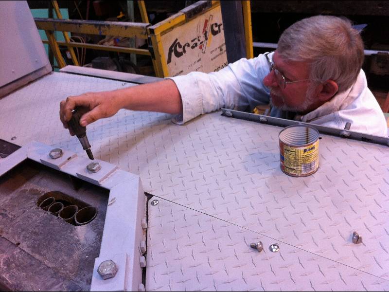
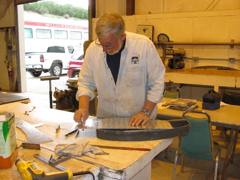
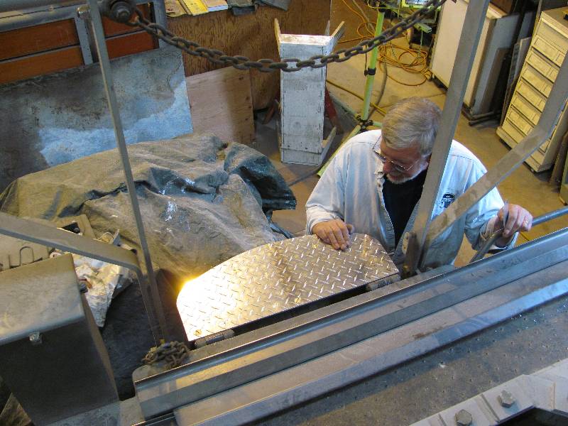
Bill
has been working on the new aluminum walkway plates for the front end.
He has done a wonderful job and all the plates fit nicely.
At
this point, the plates were
removed and sent
off to the sand blaster for a light dusting to make them match the
"patina" of the other aluminum plates on the walkways. I gave
the
deck surface a coat of the same water tank coating agent we used on the
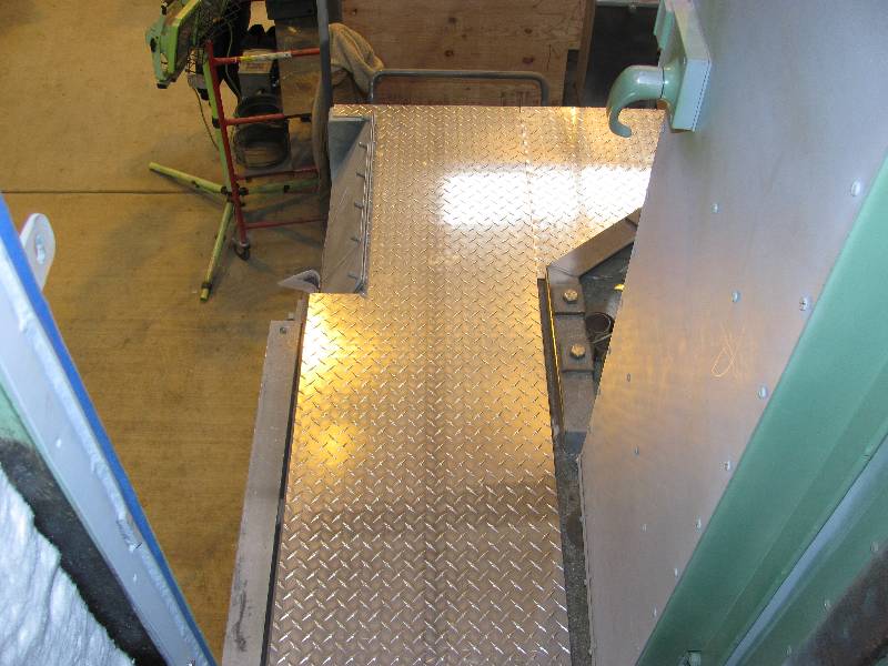
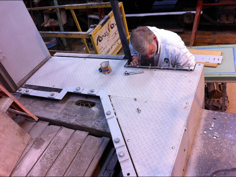
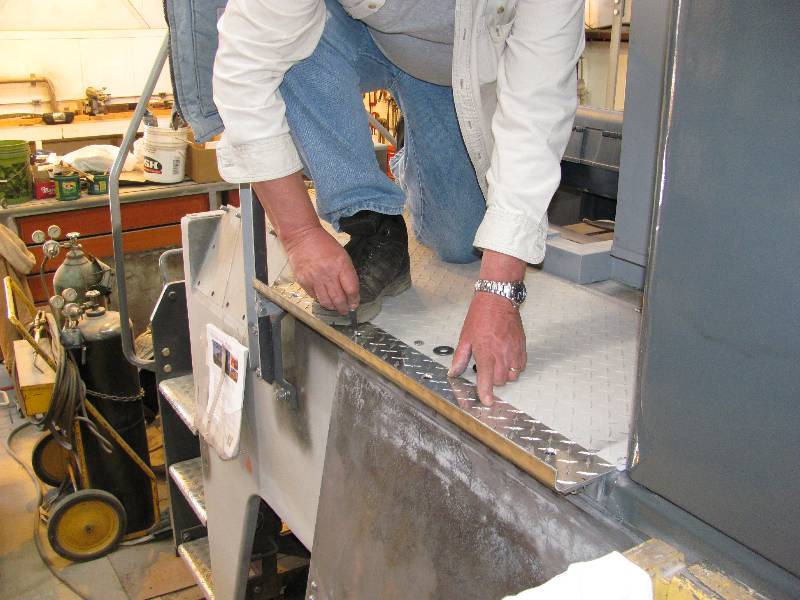
cable ducts down the fireman's side. When the plates came
back,
Bill bolted them down thus completing one more part of the project.
He then turned his attention to the small aluminum cover for
the front MU step. It was completed and installed in short
order. Then Bill completed making the front end walkway
extensions. They were taken to the bead blaster and given the
same "patina" as the floor plates.
--
Update October 25, 2012 --
Now that the new nose is in place, we were left with only finish
painting of the body and hand rails to look foward to. I
wish we could have painted the rest of the gray before the nose went on
but the stars would not align for that which led to a lot of
masking.
But once the painting was done, the hand rails and grab irons
were painted white and the decorative rings were installed around the
step well light holes. For all intents, the front end of the
9010 is done. Granted, we need sand boxes, MU hoses and another coat
of paint on the front sheet but that will come in time.
|