--
Update December 26, 2015 --
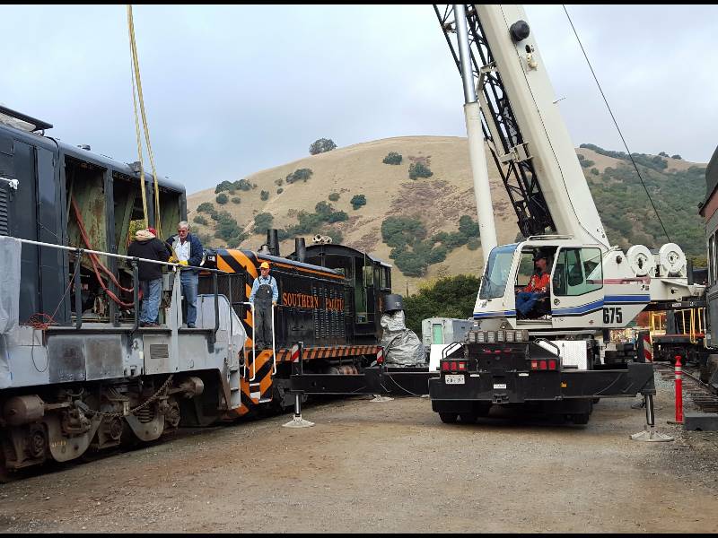
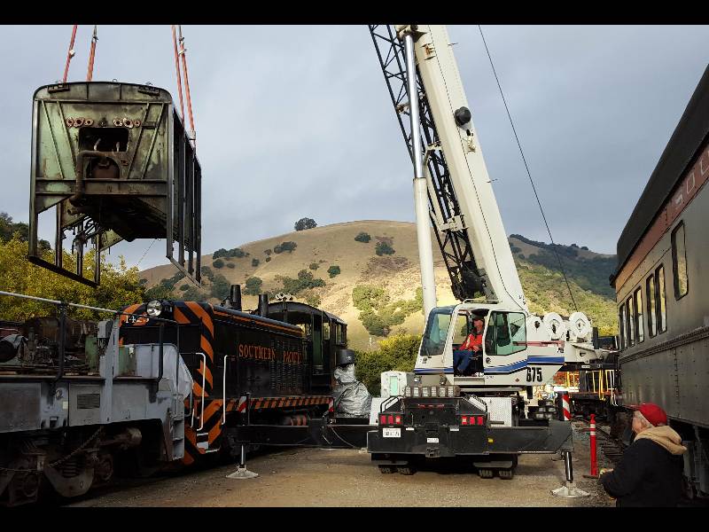
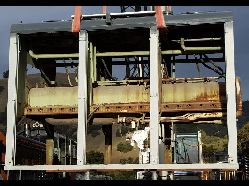
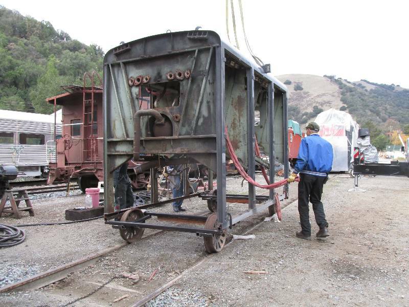
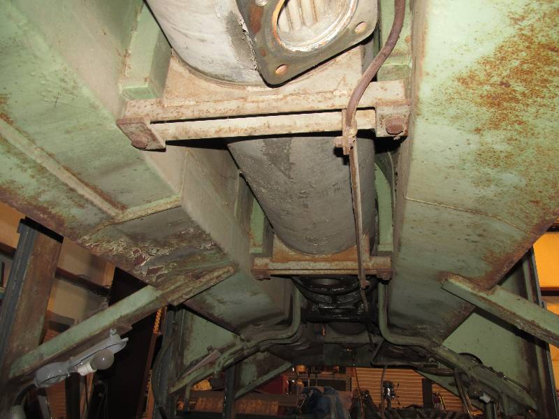
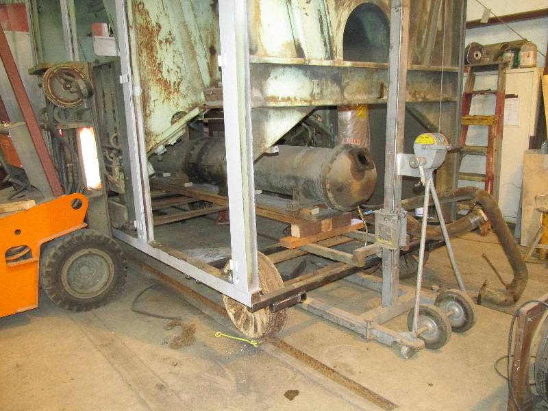
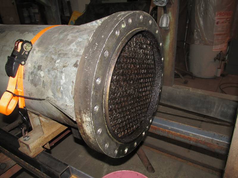
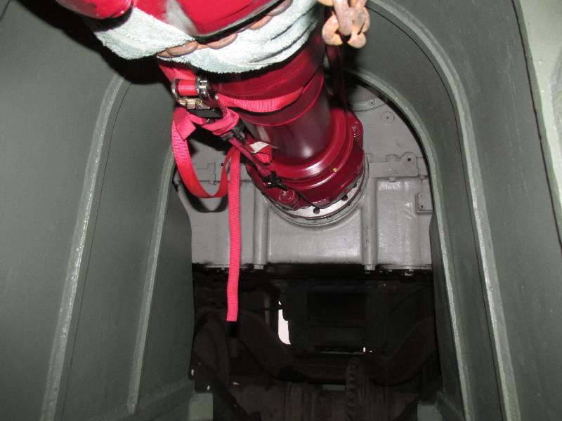
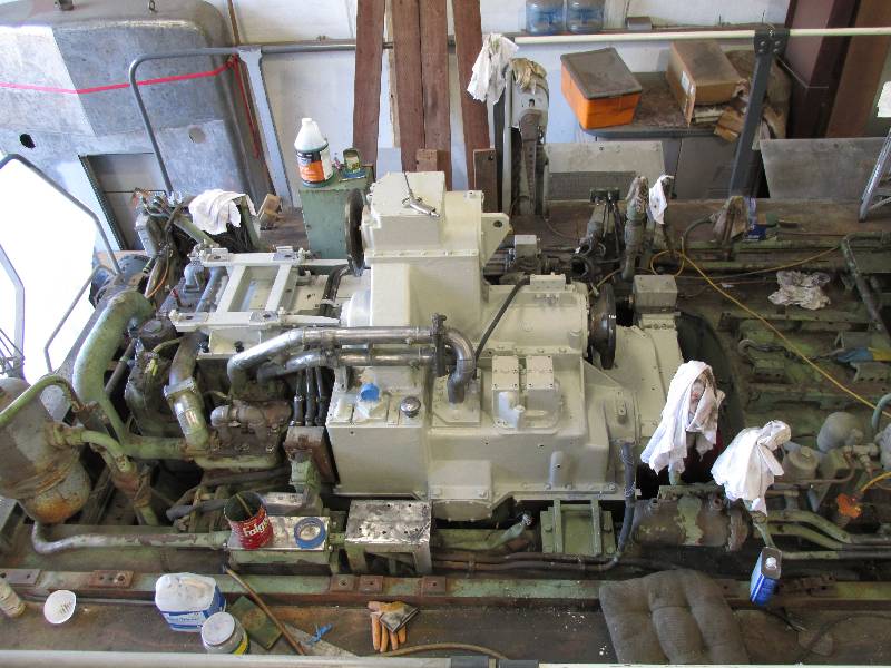
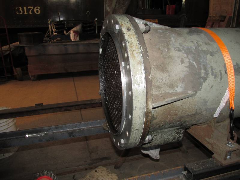
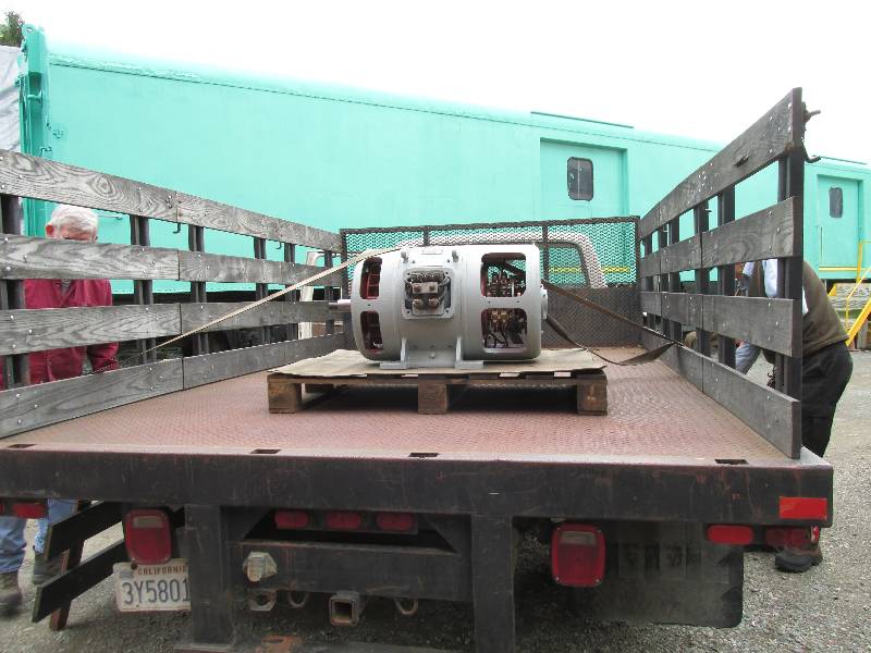
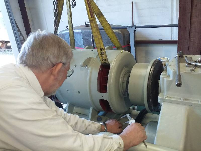
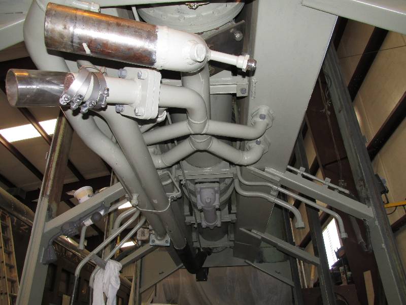
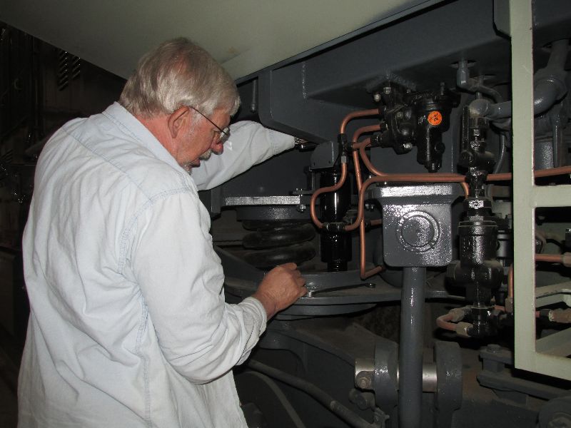
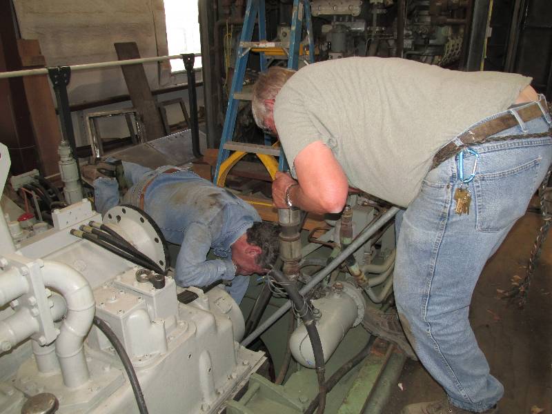
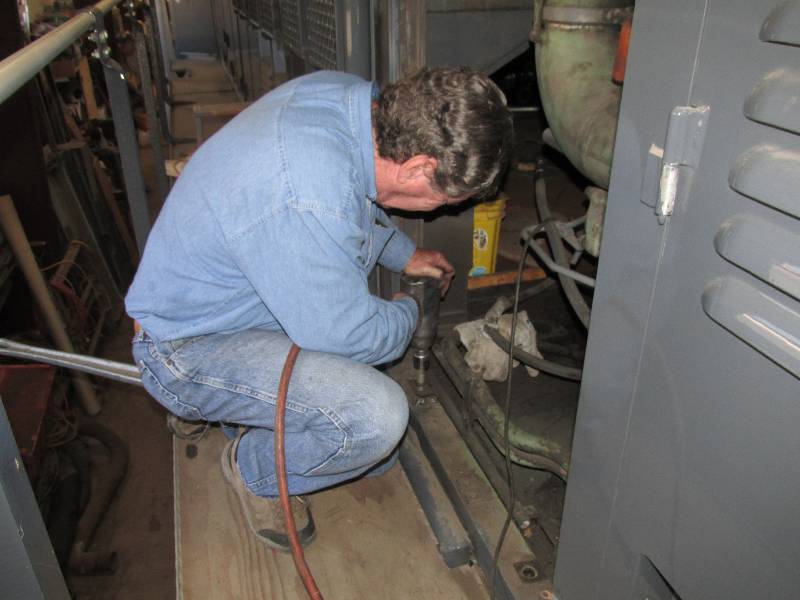
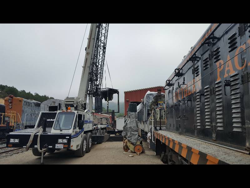
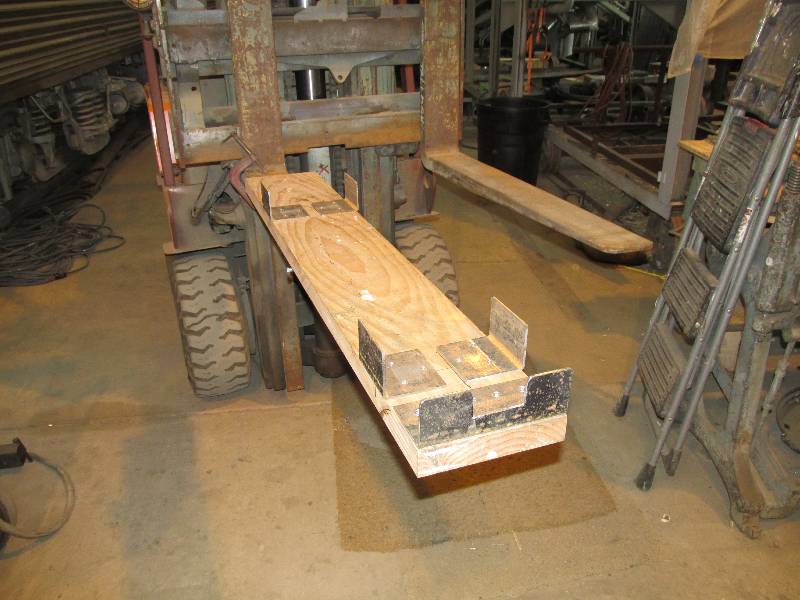
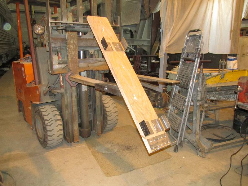
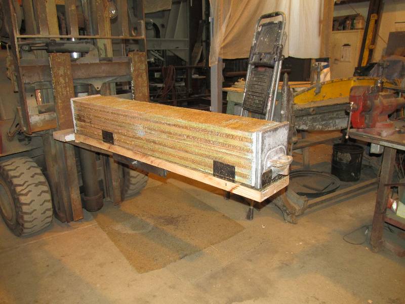
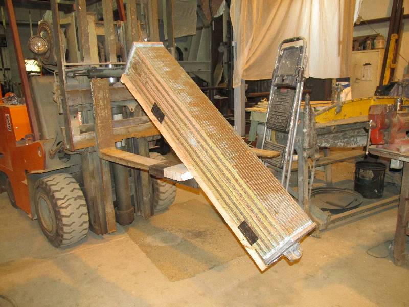
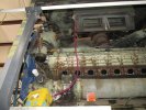
Our next chore was the lowering of the heat
exchanger. Having no idea of its weight, we first jacked up
the hood so the angle would cause the exchanger to drain as completely
as possible. After that, we rigged up a platform suspended
between two panel lifters and put the little fork lift in the center
for extra security. While quite heavy, the unit came down
with no drama.
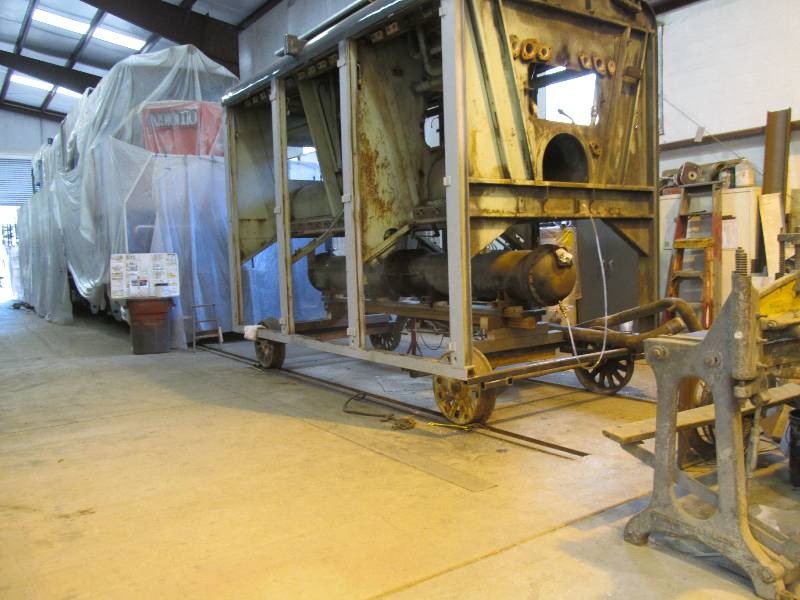
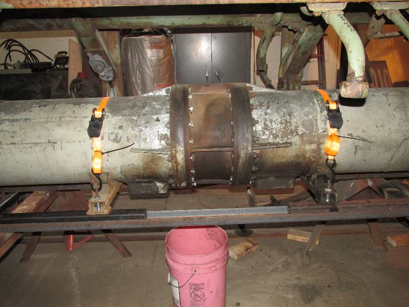
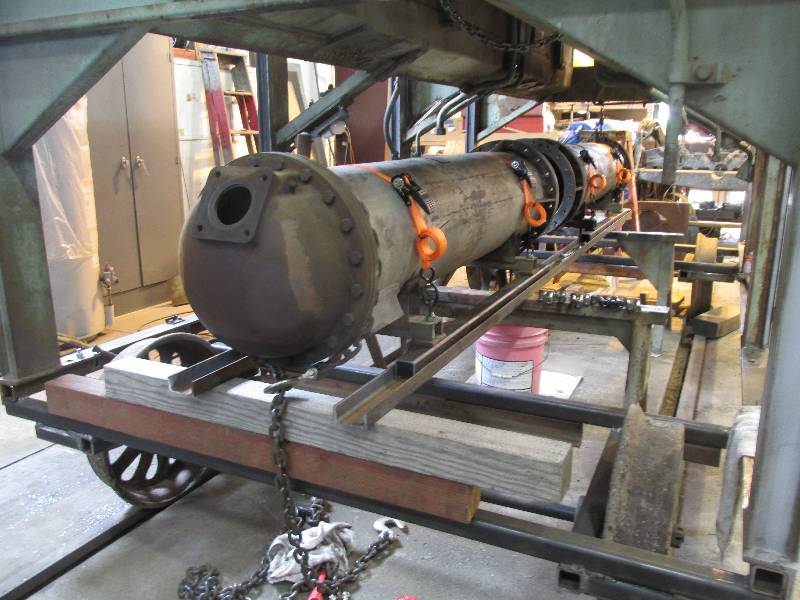
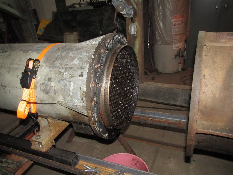
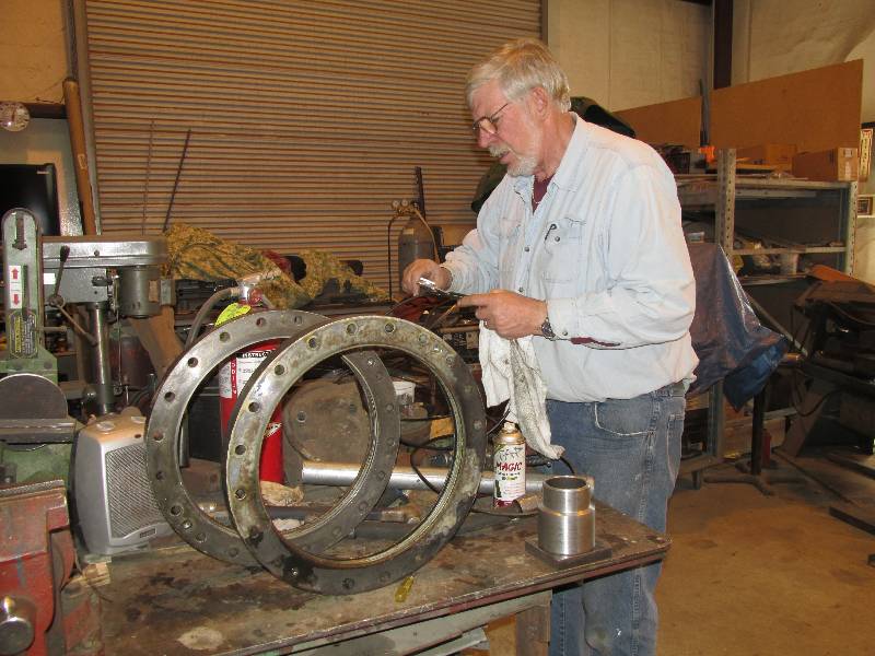
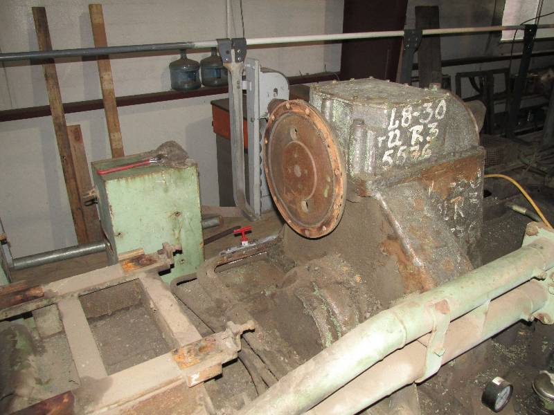
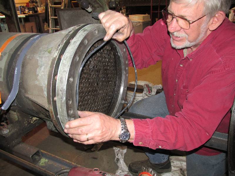
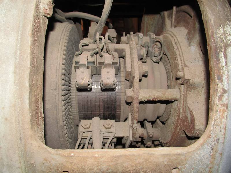
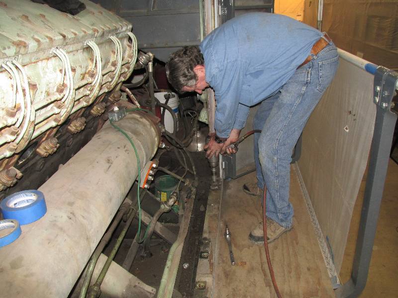
We bolted the converter feet to
pieces of 2" square tubing and put straps around the body to keep the
feet where they were. The square tubing sits in channel iron,
forming a track for the tubing. We took the bolts out of the
left side of the central piece and a few pulls on the left
end separated the converter into its two units. We then
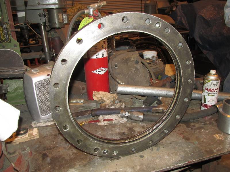
removed the central piece and finally, removed the two O-ring holders.
Bill set to work measuring everything so we could begin the
search for replacement O-rings.
Meanwhile, back at the rear end of
the locomotive, we removed the dynastarter to get it out of the way and
so it could be sent out for cleaning and refurbishing. This
will
be quite an added expense but once the hood is on,
access to the dynastarter is severely limited. We have been
able
to locate replacement rubber coupling parts at American Vulkan in
Winter Haven,
Florida and should have them on hand in a couple of weeks. It
is
amazing (to me) that they were in stock in the US and while very
expensive, they are one less item on the long list of things to worry
about.
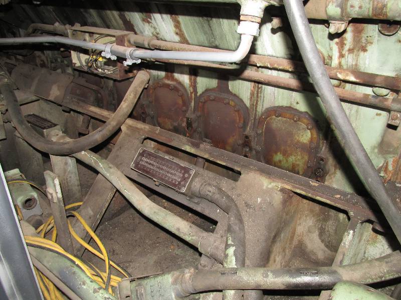
Once the dynastarter was out of
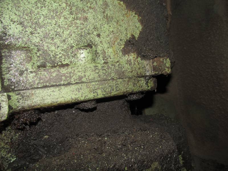
the way, cleaning began. We found some interesting painted
lettering on the transmission housing which notes the transmission
model and a number (5576) which may be a Voith factory number
as
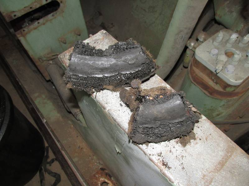
it isn't the transmission serial number. I also found pieces
of
an old dynastarter coupling which must have failed
catastrophically.
--
Update January 28, 2016 --
Remember
the number 5576 that is painted on the transmission casing?
It is
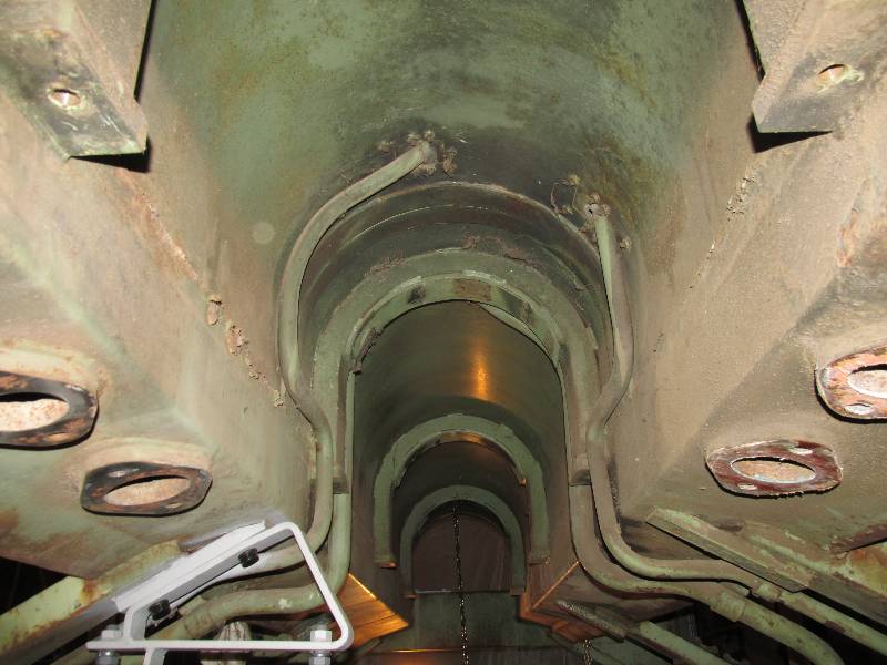
also stamped into the top and bottom covers. The tunnel
through
which the #2 cardan shaft runs had a real collection of road grime and
I could not stand having that beautiful new shaft in there so it and
the surrounding area were cleaned. The green color you see is
a
result of the green zinc chromate primer that was applied to the
locomotive frame by KM. It seems that the transmission was
also
primered in the same manner. I also cleaned and painted the
area between the transmission and engine. The paint is not a
primer but rather a direct-to-metal paint Bob Z had mixed to
match the original primer. The paint on the transmission was
also
used on the truck gear boxes.
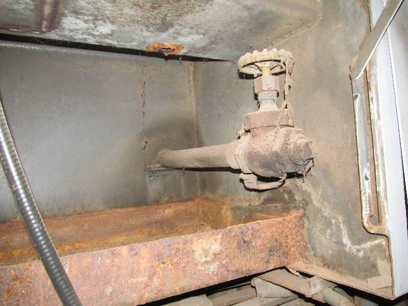
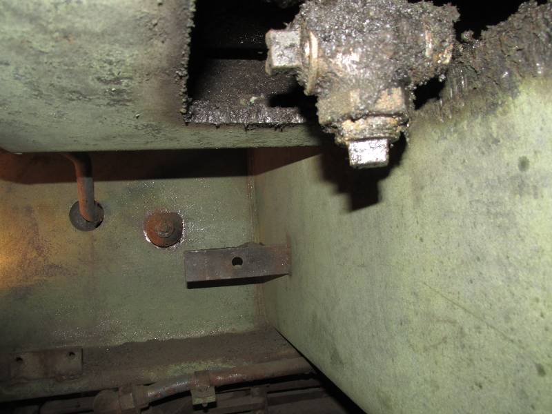
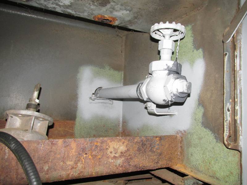
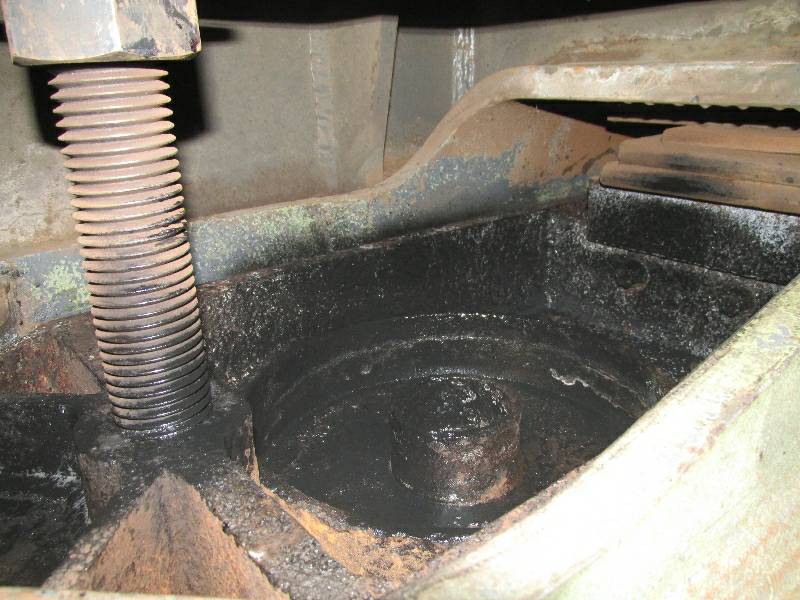
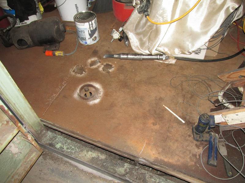
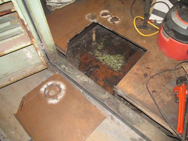
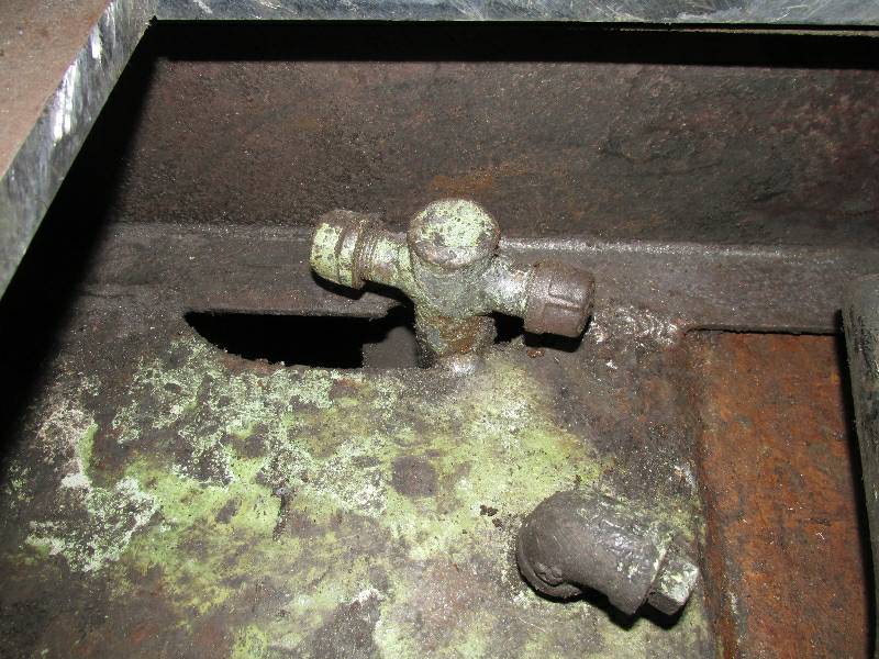
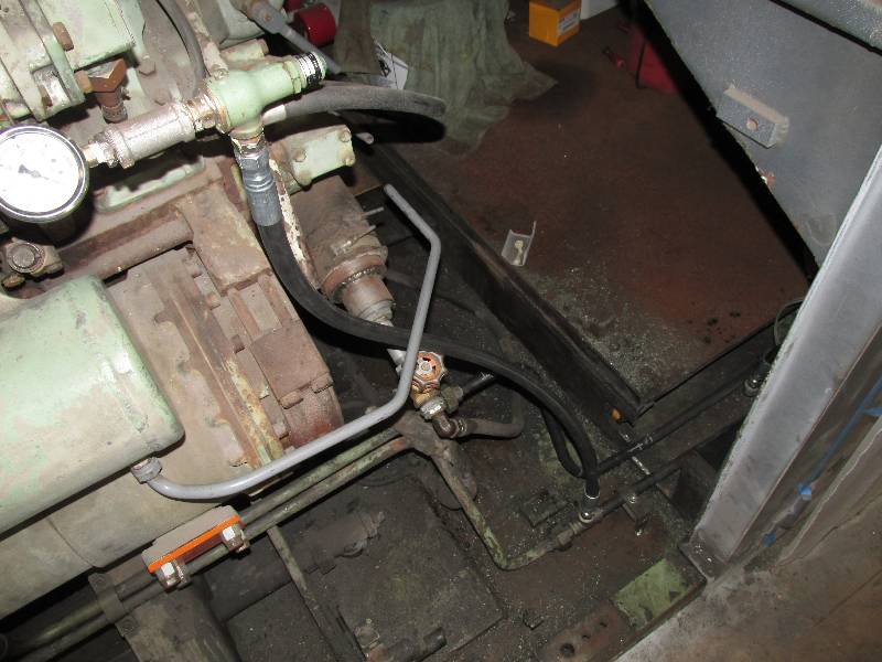
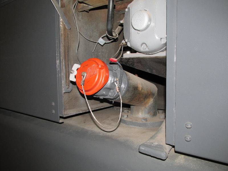
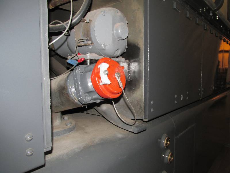
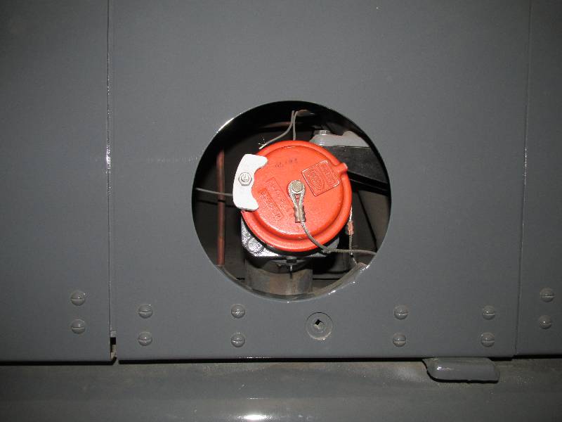
While cleaning and preparing the
area in front of the tunnel for paint, I noticed that there is no
connection between the engine crankcase and the original drain valve.
The valve in the second photo is now the engine oil drain
which is a bit odd since this puts the oil drain directly above one of
the axle gear boxes. The SP modified this for some reason.
We put the connection back using hose so engine vibration
would not have a chance to cause leaks.
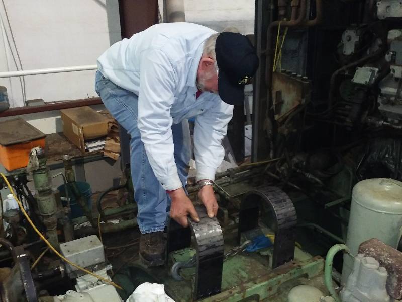
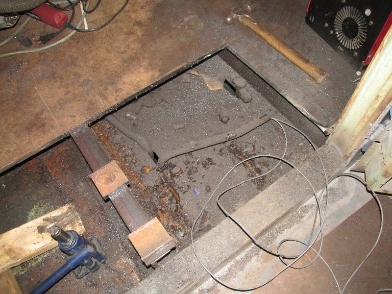
Once all of the painting of the
tunnel area was
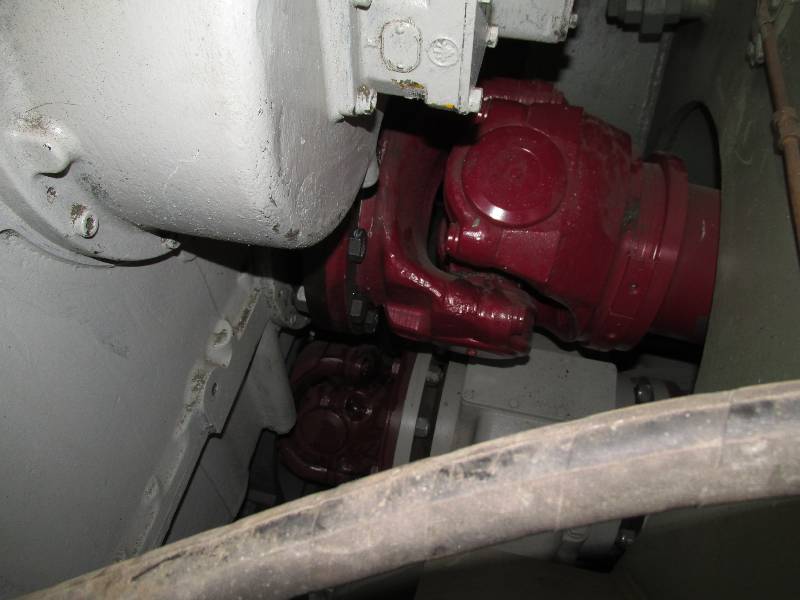
completed, we decided to install the #2 cardan shaft. This
has to
be in and coupled to the transmission before the new truck is installed
due to very limited access to the transmission coupling flange.
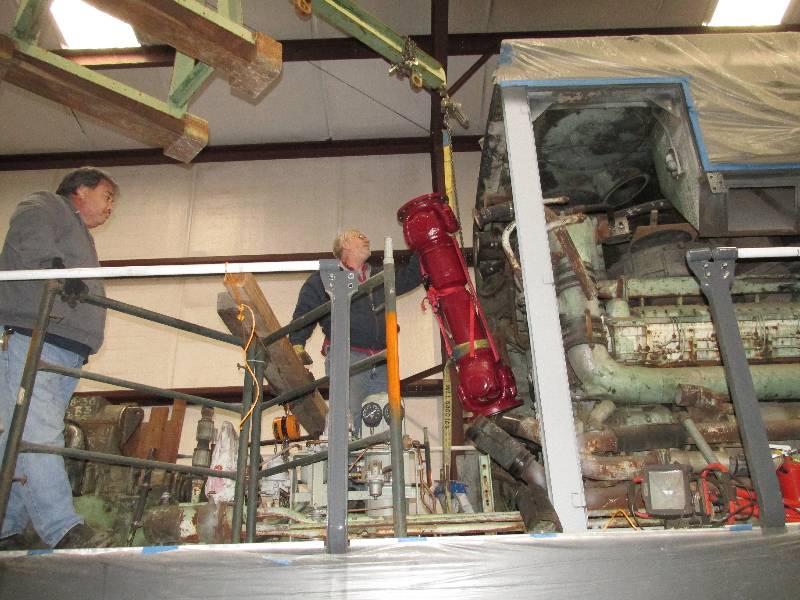
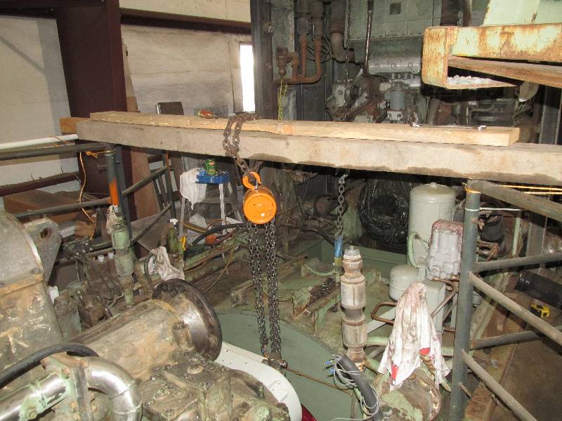
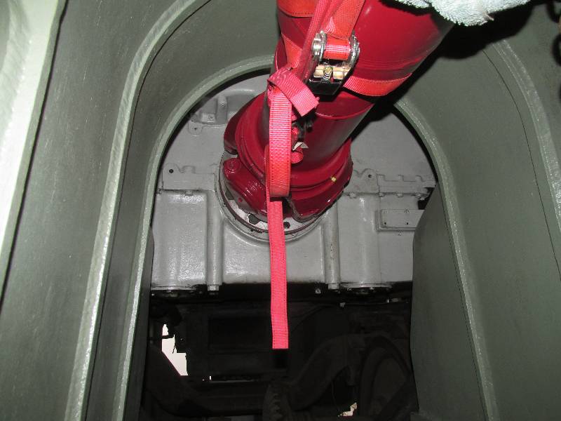
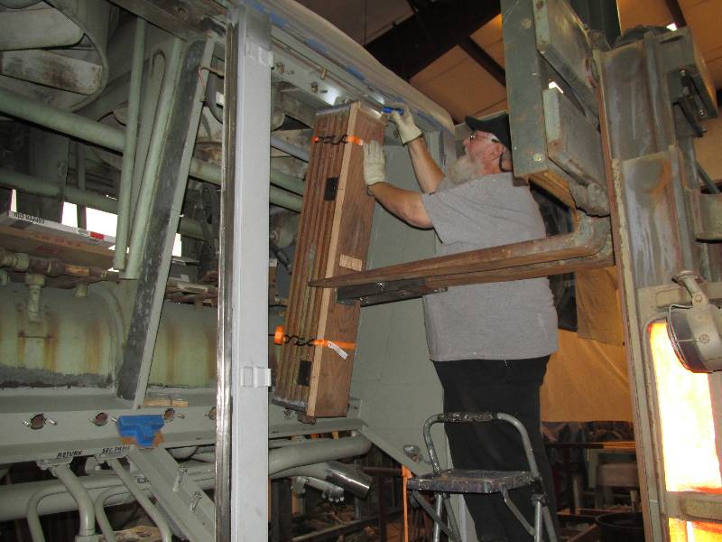
We supported the cardan shaft on one end with the fork lift
and
on the other with a chain hoist suspended from a structure we built on
the locomotive deck. The installation of the 882 pound shaft
went
rather nicely. The rear end of the shaft is now bolted to the
transmission output flange while the front end will remain suspended by
a chain until the truck is installed. The red straps seen in
the
photos are there to keep the sliding joint compressed.
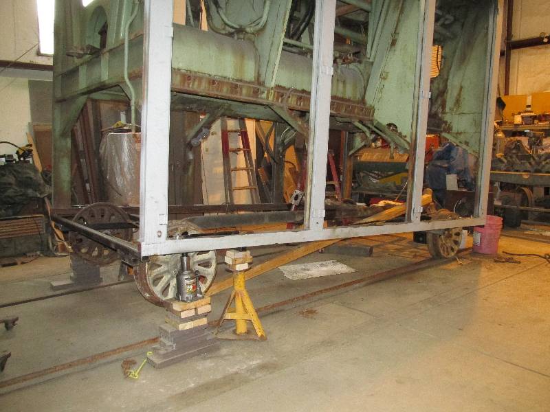
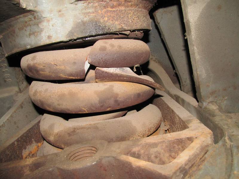
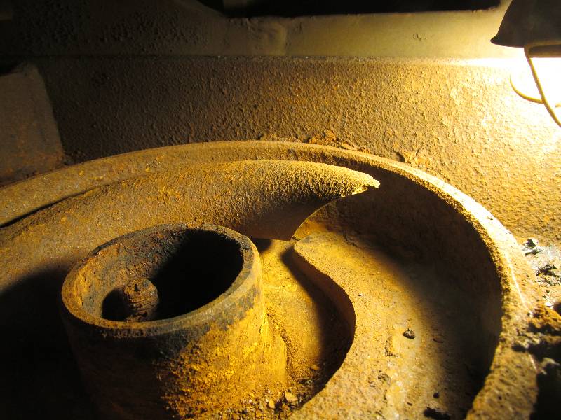
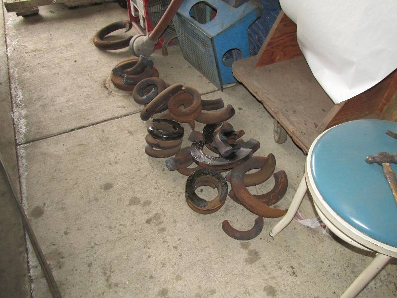
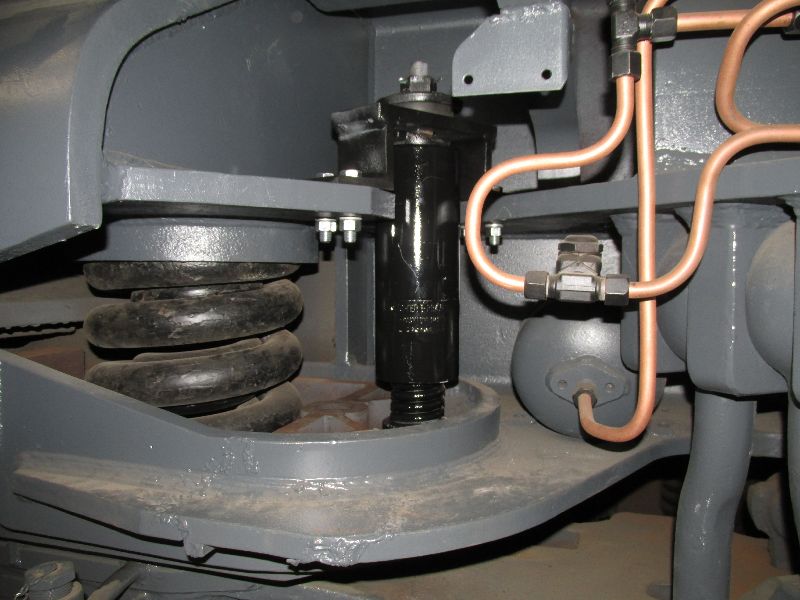
Another completed project is the
removal of
all of the body suspension springs on the left side of the locomotives.
We did this because both front and rear sliding plate
carriers have had water in them and are extremely rusty. The
rust has frozen the springs into their pockets and we cannot afford to
be cleaning this mess when we have the locomotive hanging from 2
expensive cranes when we change the rear truck. In addition,
all 4 left rear springs are broken. We have no explanation
for why just the left rear springs are in this condition but
they may have been a defective set from the spring supplier.
We plan
to exchange all of these springs with the sets we got from France as
they are in beautiful condition. This will require removing
both trucks from the locomotive but that just adds to the challenge on
rear truck exchange day.
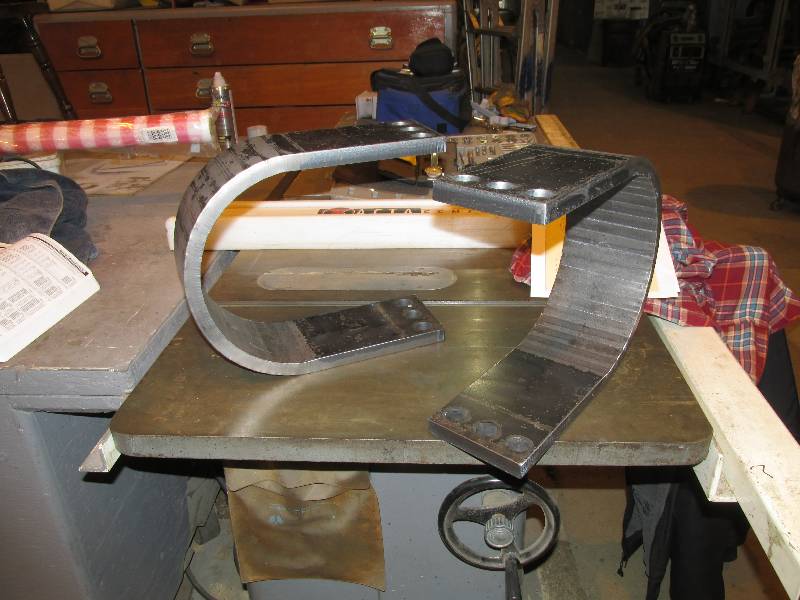
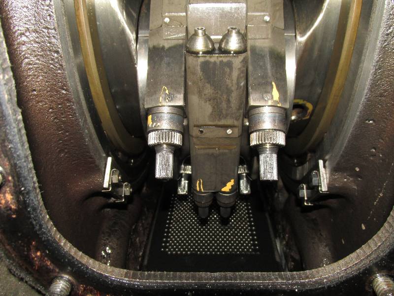
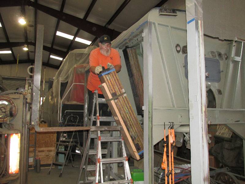
And finally for this update Bill
is test fitting the newly manufactured #1 cardan shaft safety straps.
Melrose Metals made them using an original Krauss
Maffei drawing. They fit perfectly and will be installed
after the #1 shaft is installed.
--
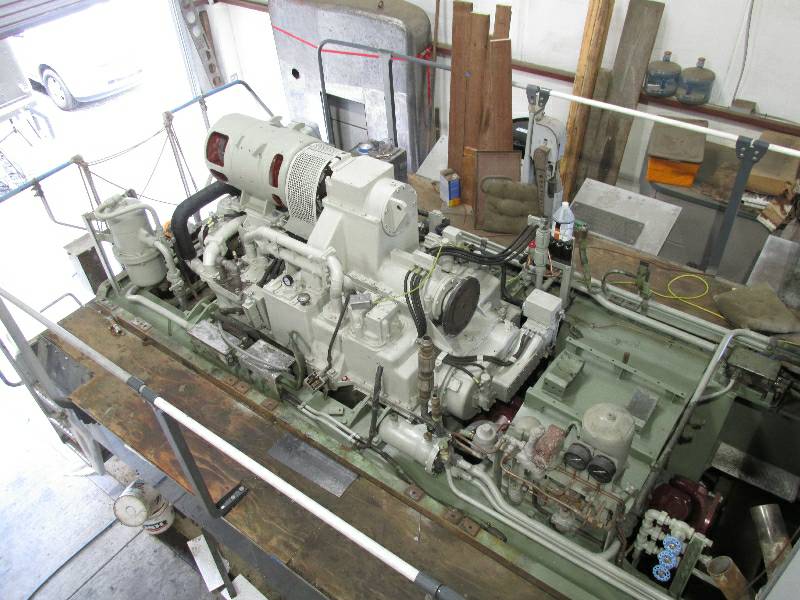
Update March 04, 2016 --
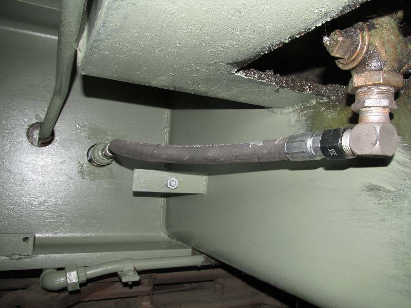
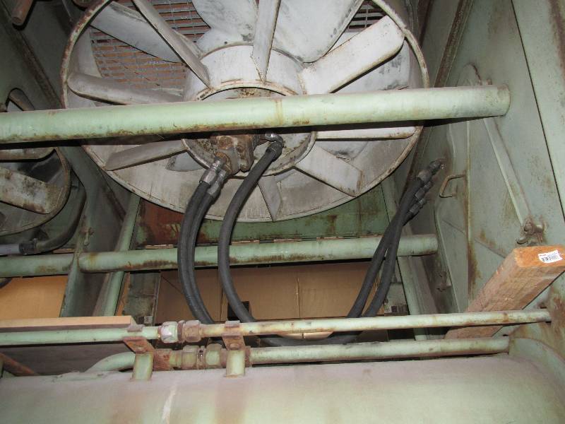
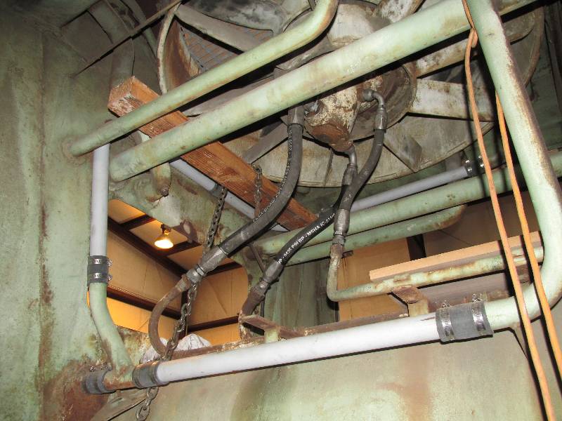
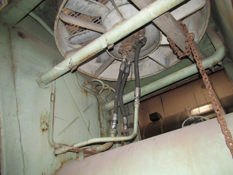
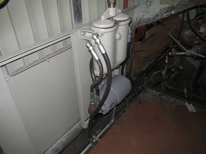
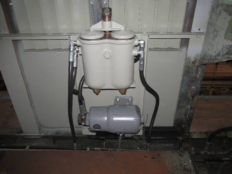
While the #2 cooling hood was off, we
replaced all of the flexible hydraulic hose lines
for the cooling motors. It is entirely possible that the old
hoses were originals from 1964. The old hoses had re-usable
ends and we owe a great deal of thanks to our friend Steve B. for
lending us his nice little hose ending machine. 3000 psi hose
is not easy to work with.
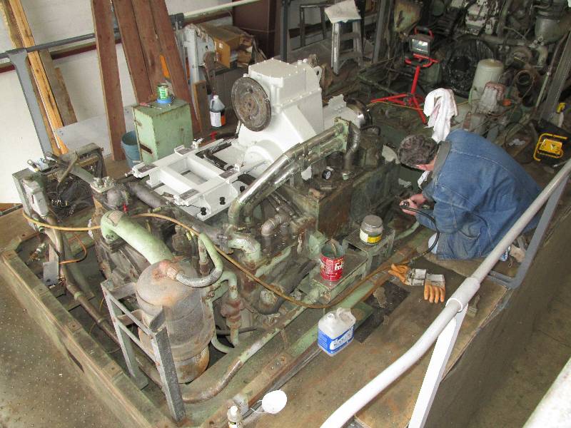
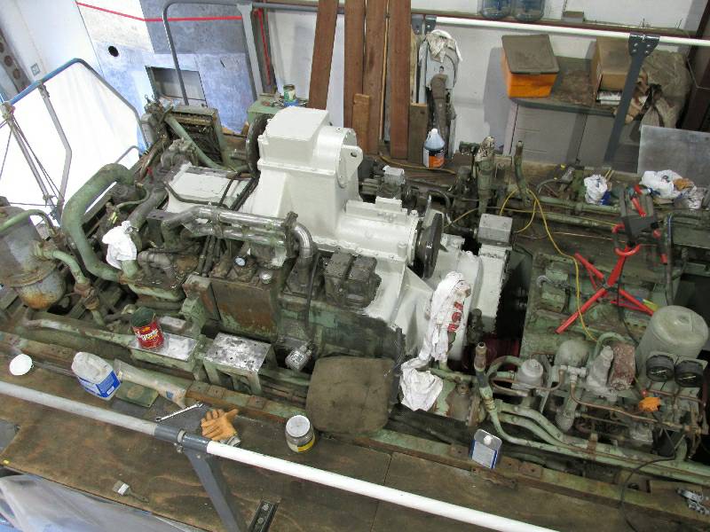
Cleaning and painting the
transmission continues with Denny taking the lead on the work.
There were hours of needle scaling and solvent washing prior
to treatment with Rust Mort and painting. While all this work
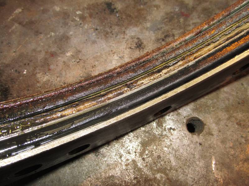
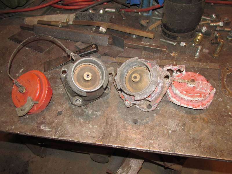
was going on, we decided to rebuild the reversing valve group.
With help from friends in Germany
and Italy, we
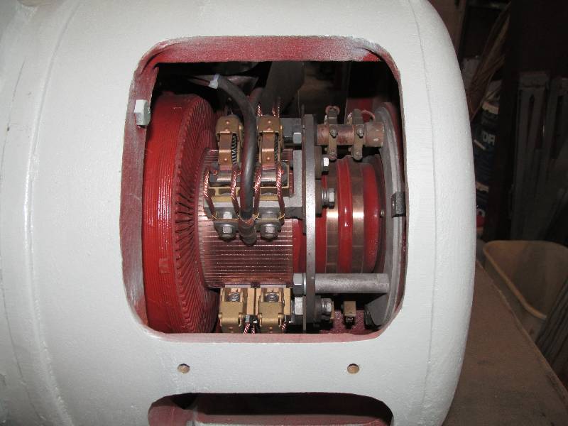
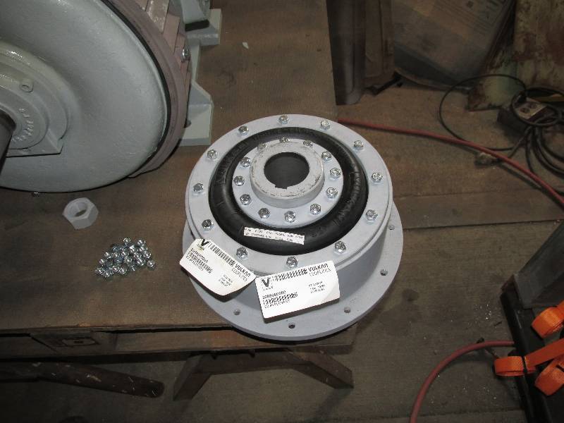
finally tracked down replacement o-rings for the heat exchanger.
After research on the other side of planet Earth, we were
able to
purchase them just 4 miles from our shop. The trick was
finding
out what to purchase and for that information we are very grateful to
Dirk and Lorenzo. As soon as the converter was bolted back
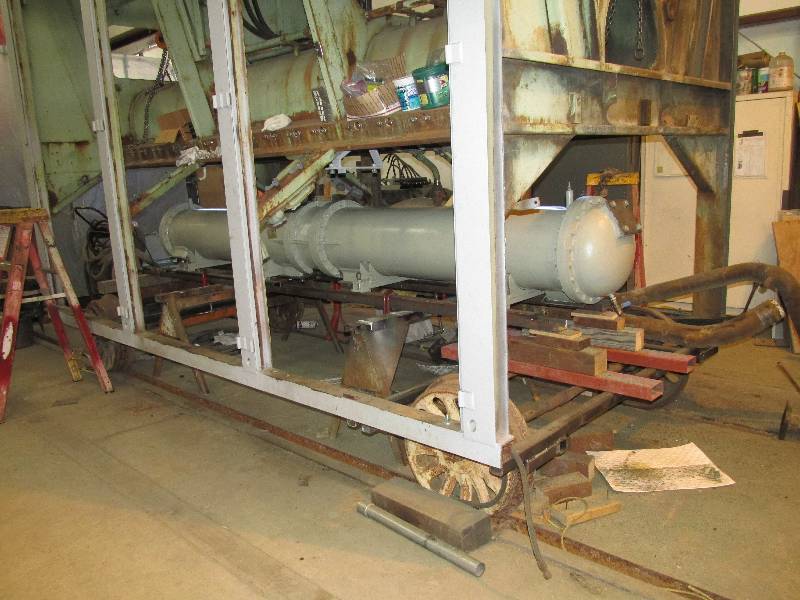
together, work began to put it back up in the cooling unit.
--
Update April 11, 2016 --
We received the dynastarter from the
motor shop and after re-assembling the coupling, installed it back on
the transmission. Rich had rebuilt and painted the safety
cover which was re-installed.
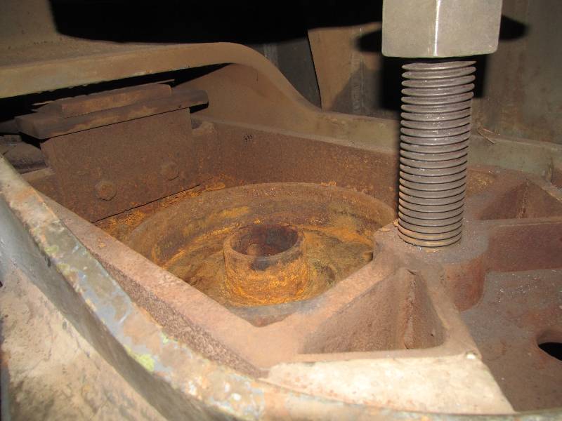
Rich has been busy cleaning
the rust out of the sliding plate carriers. We removed all of
the rusty and broken left side springs a month ago and need to have all
spring pockets
clean before truck change day. This past week, Dennis joined
the rust busters brigade. Once all the rust was gone, we
coated the spring pockets with Rust Mort to protect the metal.
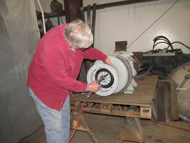
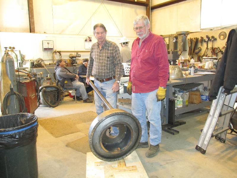
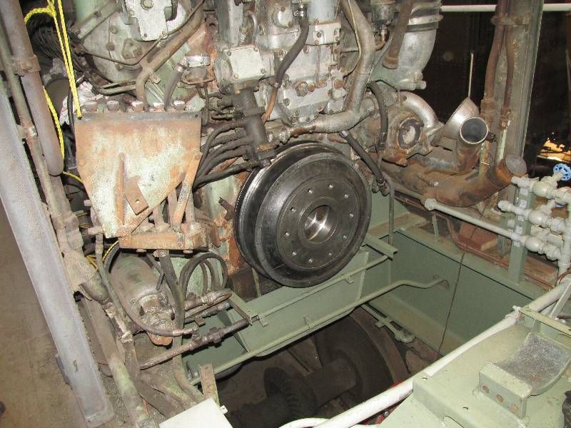
We re-mounted the lifting rig to
the newly-rebuilt
resilient coupling and with the efforts of Denny and Bill, it went back
on the engine crankshaft. This was the last major job to be
completed before truck installation.
--
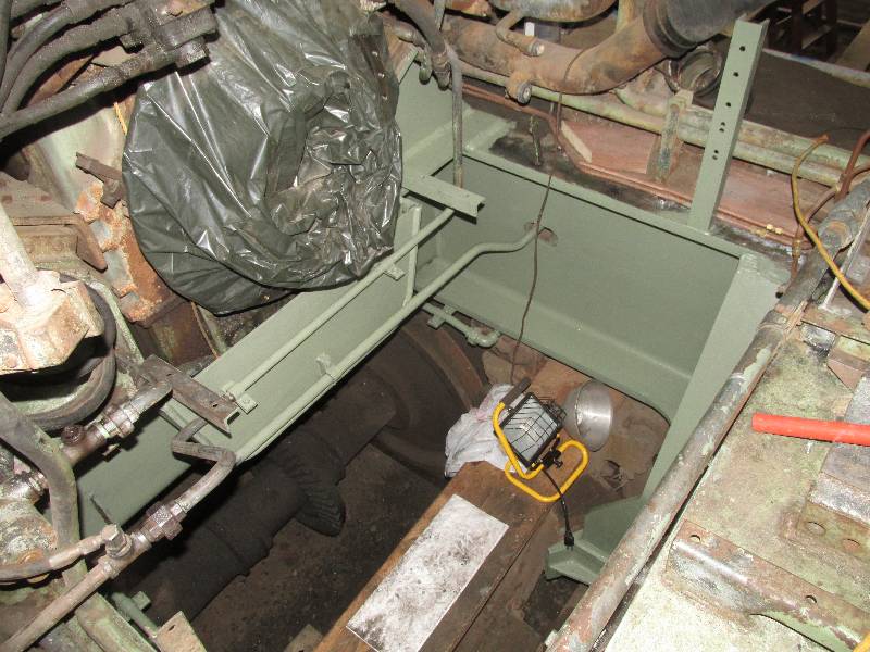
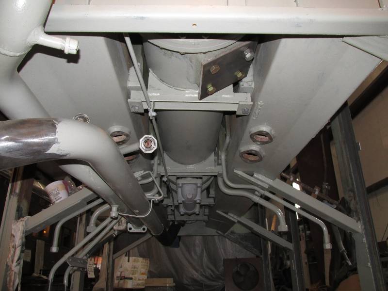
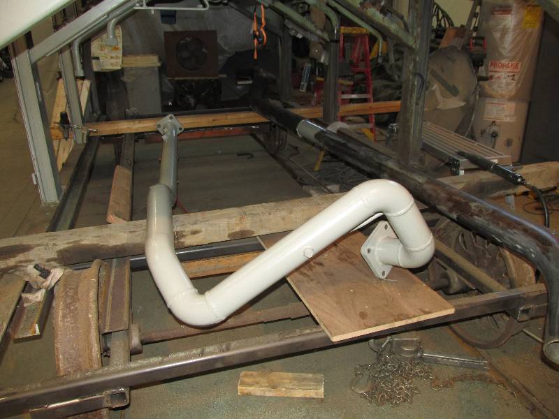
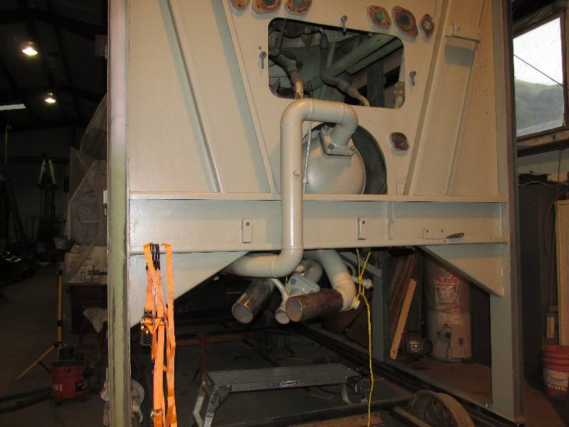
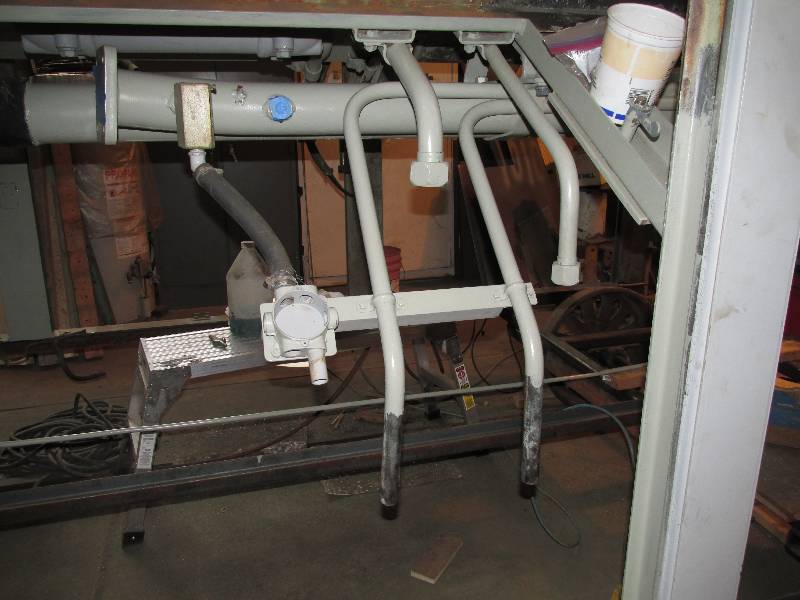
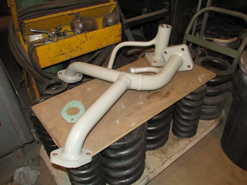
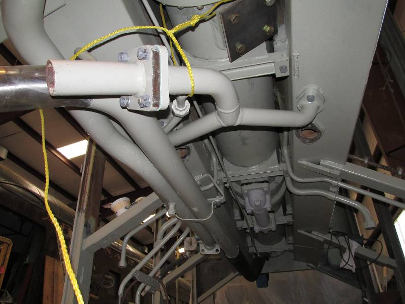
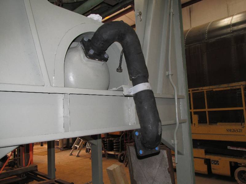
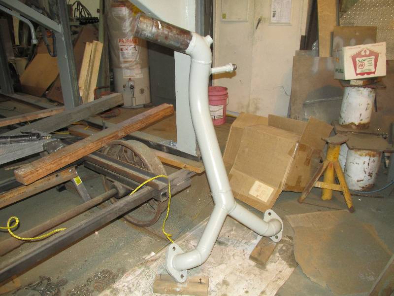
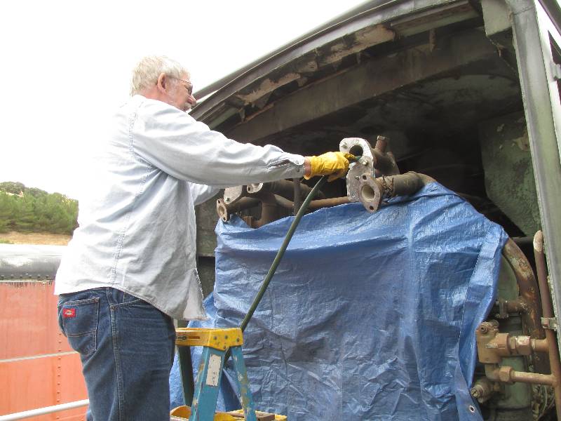
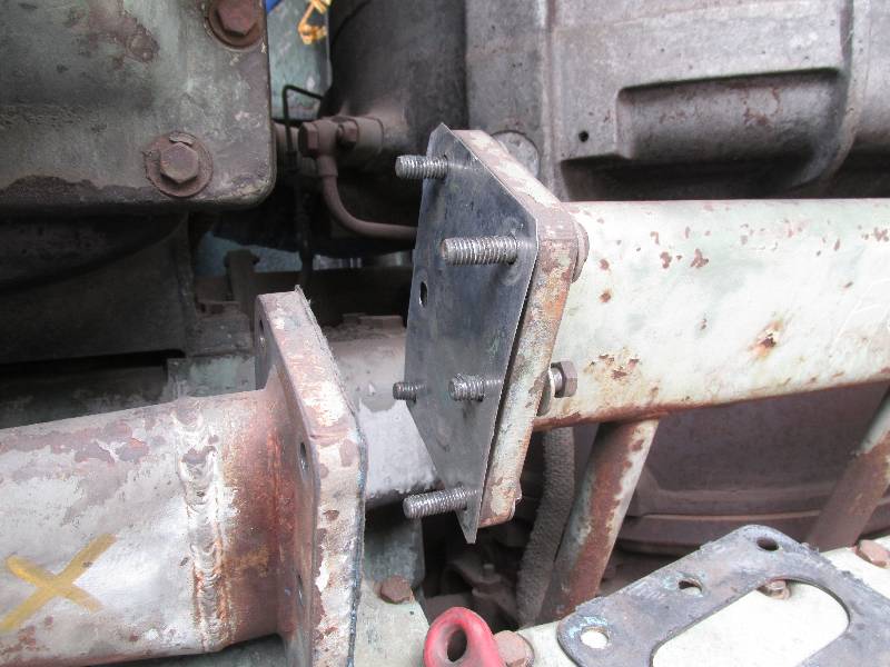
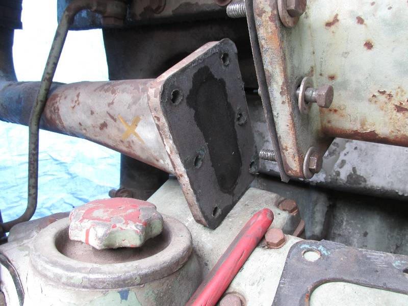
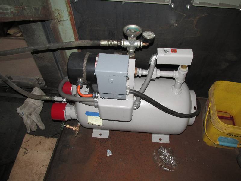
Update April 29, 2016 --
After hours and hours of cleaning and painting, the underside
of
the #2 cooling unit was ready to have its piping re-installed.
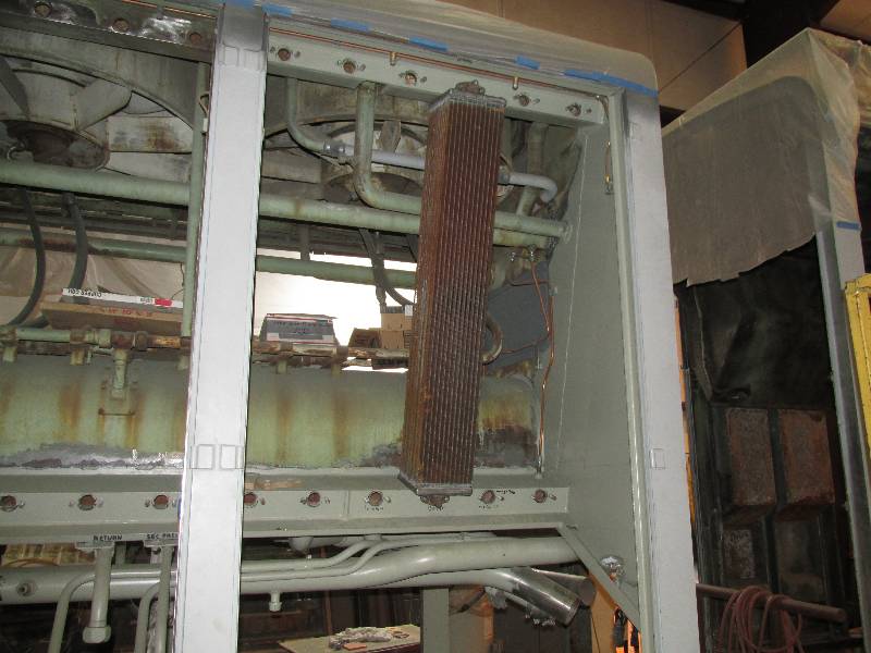
In photo #1, the large pipe on the left is the heat exchanger
water inlet line. Photo #2 is the exchanger oil inlet line
prior to installation and photo #3 is the same line bolted in place.
Photo #4 is of the inlet and outlet water lines to the
hydraulic
system heat exchanger that is mounted on the locomotive frame.
Photo #5 is of the turbo intercooler radiator collector lines
and
photo #6 is of these same lines bolted in place. Photo #7 is
of
the exchanger oil outlet line that will attach to the transmission.
Photo #8 is of the engine radiator collector line after
cleaning
and painting and photo #9 is of the same line back where it belongs.
This completed work on the underside of the cooling unit.
 |
--
Update May 18, 2016 --
Very little work has been done on the number
2 Maybach but that changed on May 14th. With Rob here from
England, it was a great time to undertake some exploration.
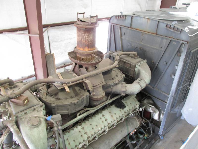
We decided to open the crankcase and have a look.
The most important issue was the condition of the roller main
bearings. Getting access to the bearings (and crankshaft,
connecting rods, etc.) is no easy task because even though there are
access doors, they are only 6x8 inches and hidden behind the motor
mounts. We tipped the engine slightly with a hydraulic jack
and were able to remove one section of motor mount.
Rob then removed 4 of the doors to reveal - an unbelievably
clean crankcase interior. Sadly, I did not take a photo of
the motor mount before its removal. We and our Maybach
advisers are satisfied that the lower end is good for startup.
--
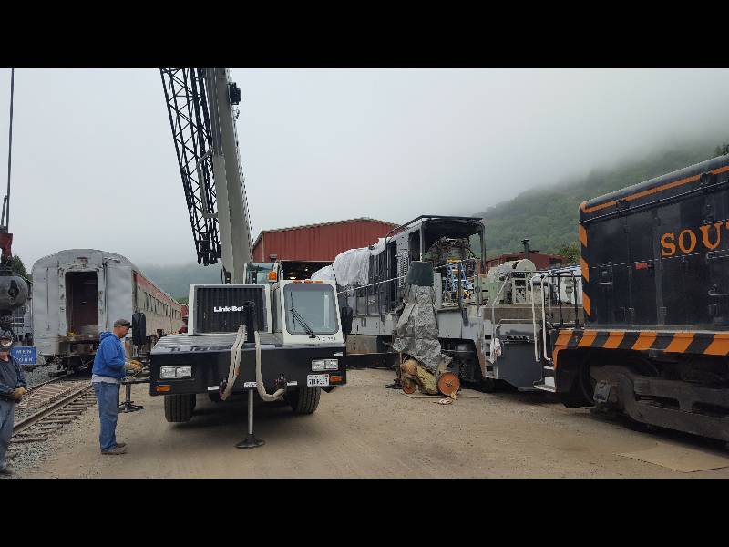
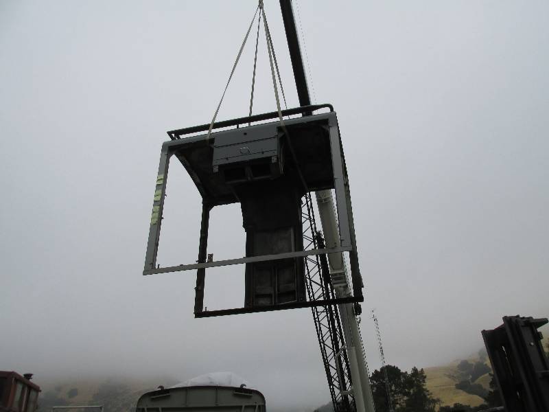
Update August 17, 2016 --
Now that the major truck work is completed,
we started putting the friction dampers back on. Rich spend
hours bead blasting the parts and then Bill gave them a coat of primer
and black paint. Once dry, Bill started putting them back
where they belong. Of course, the frame areas around the
damper mounts had been needle gunned and painted.
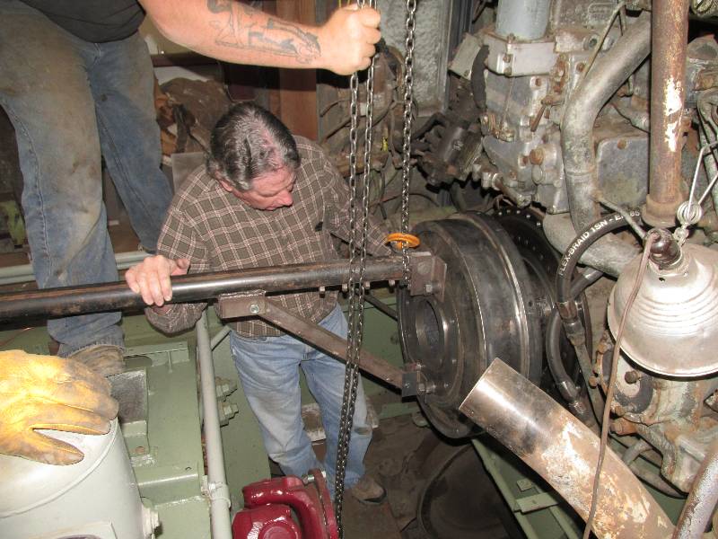
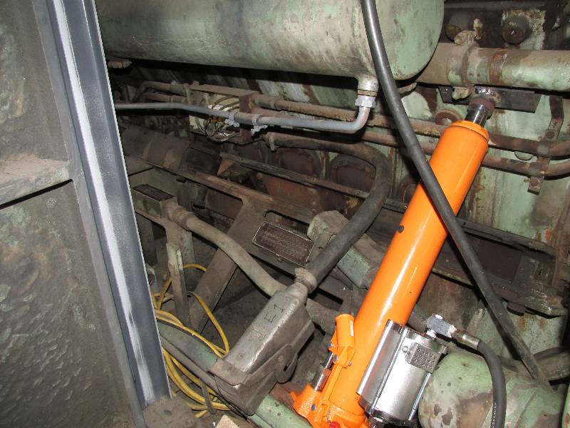
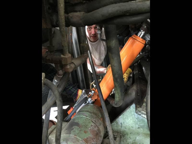
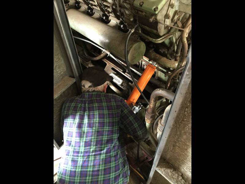
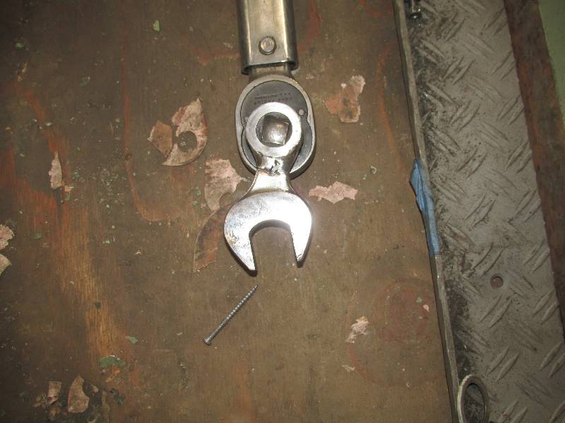
Bill and Dennis took on the job of
torquing the bolts that secure the #2 cardan shaft to the transmission.
Since there is no way to access this coupling from under the
truck, Dennis was forced to lay down in order reach the bolts and help
Bill hold the end of the torque wrench in place. We made a
special tool for the wrench as it was not possible to use a socket.
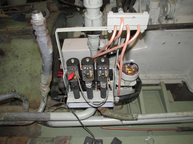
The next item on our list was
filling the engine block with water and checking for leaks.
The
water inlet of the block was plugged and Bill attempted to put water
one of the outlet pipes. These pipes would normally connect
to the top tanks of the radiators. After a few seconds, the
water backed up in the pipes and would not flow into the engine.
We discovered that someone had put blocking plates into the
pipes. We cannot think of any logical reason why this was
done but it certainly is a curiosity. After the plates were
removed and the block began
to fill, we found the main water pump leaking out of its seal -
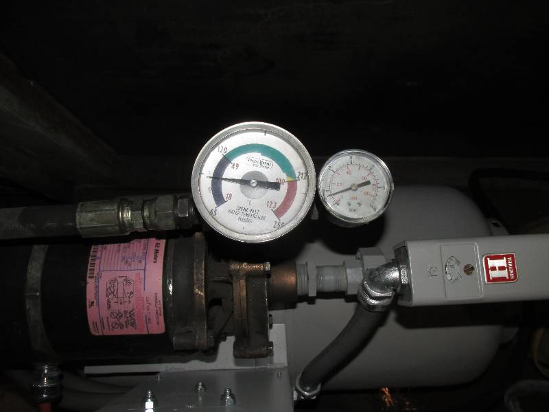
something else to fix. I installed a piece of clear plastic
tubing to act as a level gauge. The pink color seen in the
tubing is a result of adding a treatment compound to the water
in order to avoid corrosion in the engine. The Southern
Pacific did a great job of water treatment and there is no rust in the
engine. We want to keep it that way.
 |
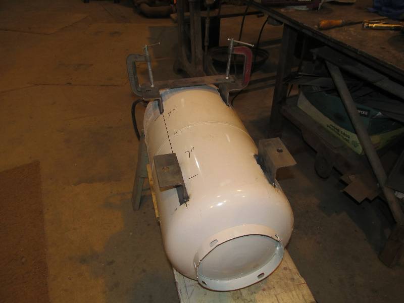
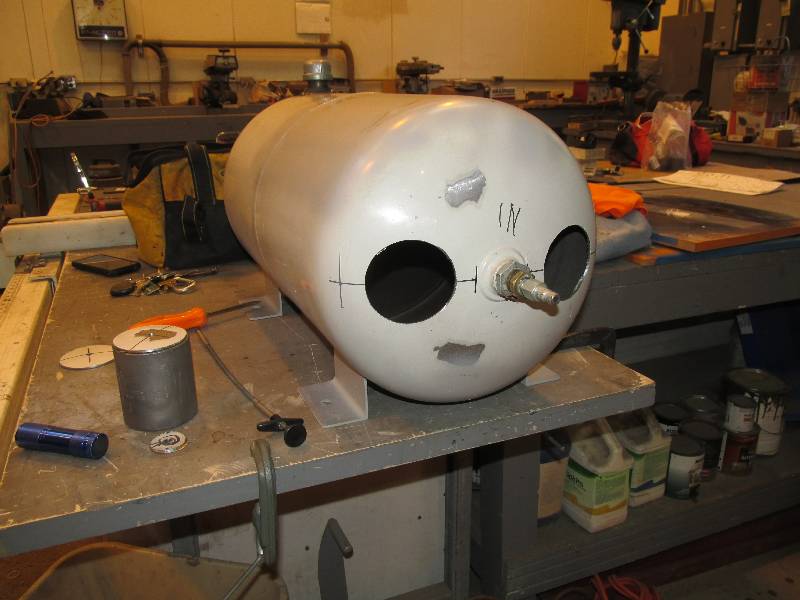
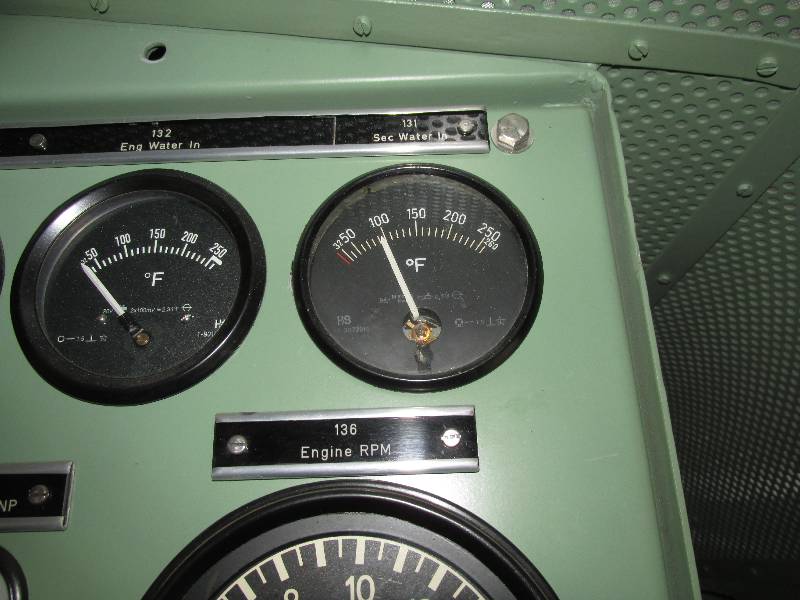
Starting the Maybach requires that
the water temperature be brought up to 90 degrees F. The 9010
was originally equipped with diesel fired pre-heaters which
were
thrown out during camera car conversion. Because the 9010
will
be in a museum setting and never far from power, I decided to build an
electric heater using a 10 gallon propane tank. The heater
has two 4000 watt electric heating elements, a pump and controls to
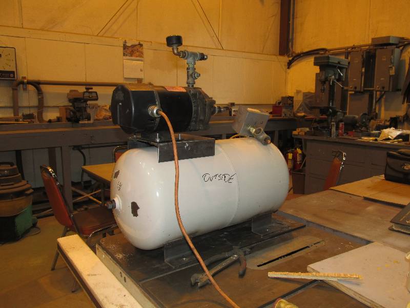
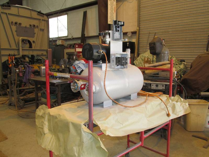
manage the water temperature. After connecting the heater and
allowing it to run, I found that it provided a water temperature of 95
degrees as indicated on the gauge in the cab. The pressure
gauge is indicating the back pressure on the water but the pressure
shown is only that in the line between the pump and the engine as the
engine lines are open to the atmosphere. Having the heater
will help in finding leaks and the pump will be able to circulate water
in the block when we attempt to start the engine.
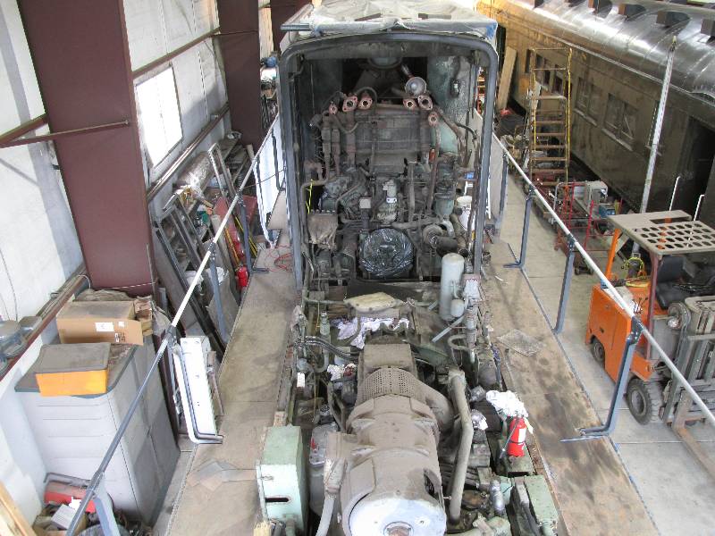
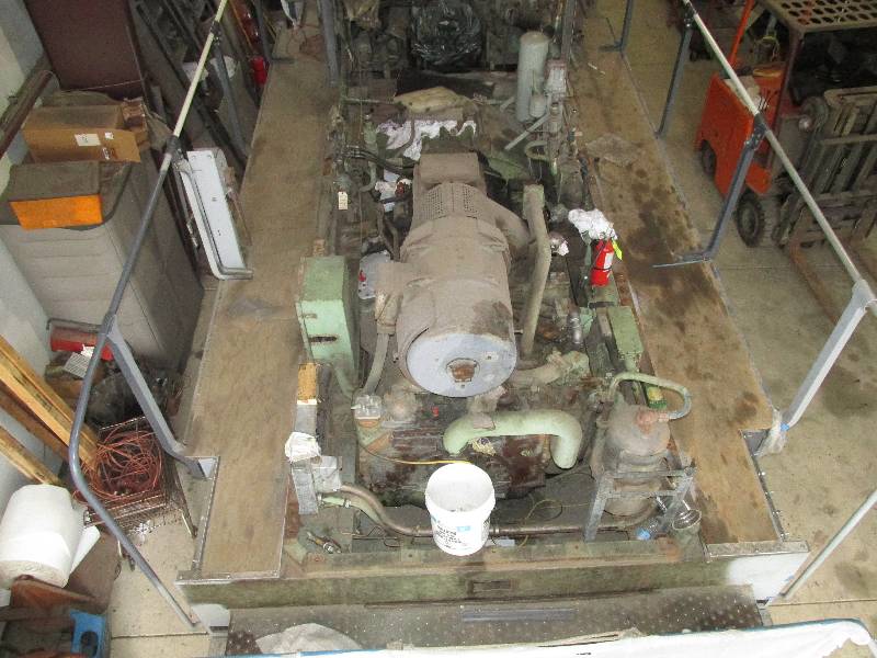
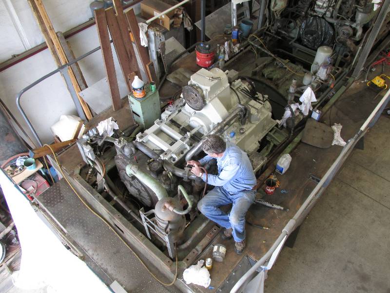
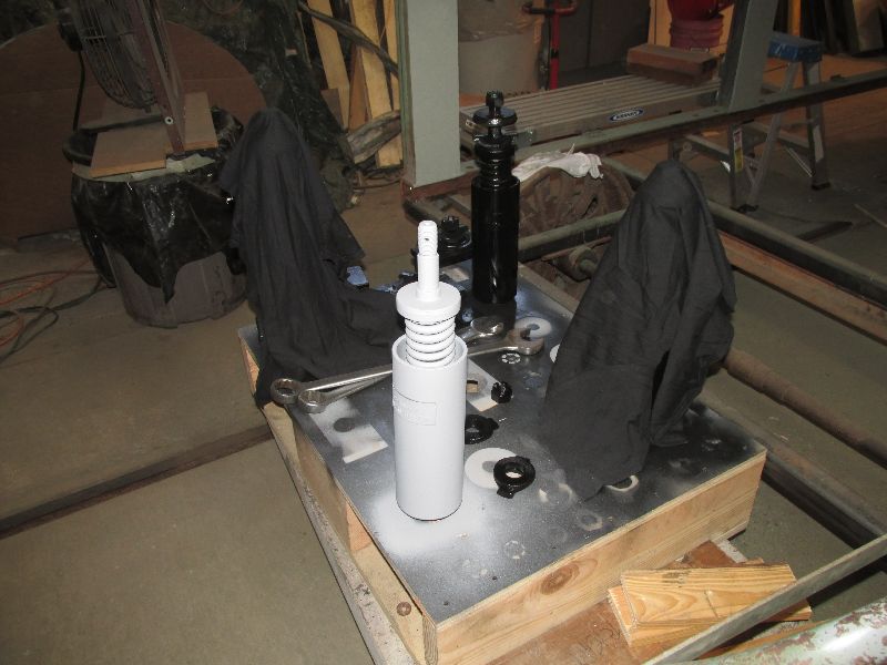
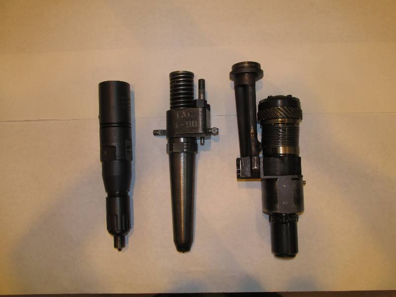
One big issue with the engine is
the injectors.
Having sat with fuel in them for over 40 years, half of them
are
frozen from the solidified fuel and the other half are not trust
worthy. I removed one from the #1 engine just to test the
removal
procedure and took the opportunity to compare the L'Orange to an EMD
and Alco injector (Alco is on the left and EMD is in the center).
The L'Orange and the EMD are both unit injectors while the
Alco
injector requires an external pump. I decided that working on
the
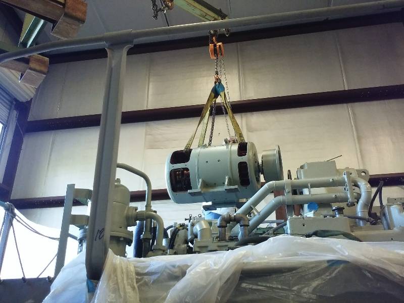
#2 engine would be much easier if the hood were removed so jacking bolt
pads were welded to the hood frame and Dennis ran them in which raised
the hood locating pins out of their holes. Our friends at
Peninsula crane sent over a unit and the hood was soon on a
cart
and in the shop. The engine is certainly easier to see now.
--
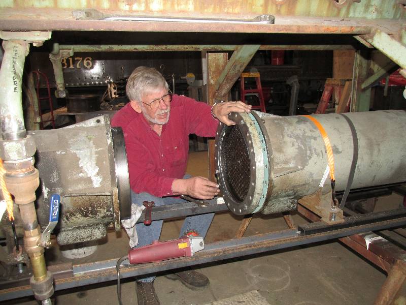
Update November 25, 2016 --
Work
on radiators has been progressing very slowly.
We have only
7 of the original Behr cores, all of which are damaged beyond use.
Bill made contact with a local radiator shop, the
owner of
which is interested in the project and has been combining our old core
ends with new cores. Bill, Rich and I attempted to install
one by
hand and found that due to the limited space and the weight of the
core, we could not do it. So, I build a gadget that mounts on
a
fork lift blade and removes all the lifting problem. Rich
and I
installed the 3 new cores we have on hand and are very pleased with the
results.
 |
 |
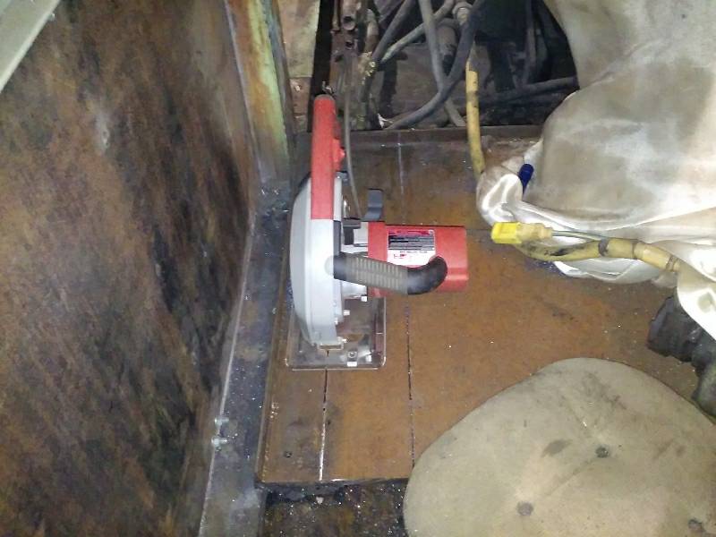
When the locomotive was converted into the
camera car, the SP removed all vestiges of the original fuel system.
The pumps, filters, hoses and such are all gone.
One thing
I have never understood about the original system was the lack of a
fuel filter on the suction side of the pump. I decided that I
would install a pump and filter system like that found on EMD
locomotives using EMD parts. There was one significant
problem
with this idea: the false floor installed in the #2 cooling
room
covered all of the fuel lines and that floor is 3/4" thick steel.
There is quite a greasy looking accumulation between the
false
floor and the actual floor so using any sort of heat producing cutting
method was out. I decided to use metal cutting blades in a
specially built Milwaukee saw to do the major part of the cutting and a
reciprocating saw to finish the rest. The metal cutting
blades
are not meant to cut 3/4" thick steel so cutting was very slow with a
lot of time given to cooling the blade.
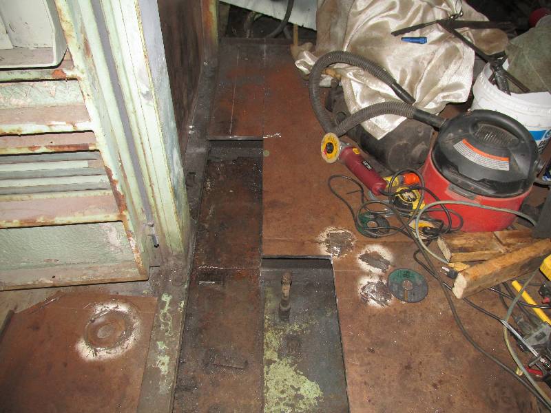
The first cuts removed the section surrounding the #2 engine fuel
suction pipe.
In the first photo, you can see where this pipe had been
extended through the false floor so the camera car diesel generator
could connect to it.
The next cuts exposed the #2 engine fuel pump power
conduit, #1 engine pre-heater fuel suction and a fuel return
line. The connections seen in the second photo tell an
interesting forensic tale. The plugged elbow was the fuel
suction line for the #1 engine pre-heater. The left side of
the "Tee" was the fuel return line for the #1 engine pre-heater and the
right side was the fuel return for the #2 engine. After
cleaning the Tee, I noticed that the right side cap is bare metal and
the left side cap is painted green. The green paint could
only have been applied during the 1966 upgrade which means that the
piping connected to the left side was removed then. The
conclusion is that the engine pre-heaters were removed (or at least
disabled) in 1966. Evidently the Maybach engines started
without pre-heating in the California weather or the Southern Pacific
simply did not want to mess with them.
The next photos show cuts made to expose an area for the fuel and power
lines to run. First is a shot of the Milwaukee metal saw.
What a great gadget!! Once the necessary metal was
removed, the wall was painted, piping was installed and clamps were
made and welded to the floor.
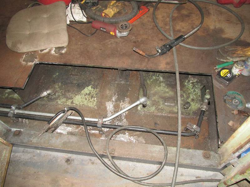
Meanwhile, a mount for the dual filter housing and pump was constructed
and installed. Fuel is drawn from the tank through the
suction side filter by the pump. It is then sent through the
pressure side filter and on to the engine.
While looking around under the false floor, I noticed that the mount for
the #2 6-cylinder Westinghouse air compressor was still in place.
Also seen in the photo is the circular saw blade making its
way through the false floor.
The Snyder fuel filler assemblies had been
removed and replaced with pipe plugs. Photos of the camera car do
not show filler caps so this must have been done during camera car
conversion. Our good friend and project supporter Matt Monson
provided us with a pair of filler assemblies for which we had to create
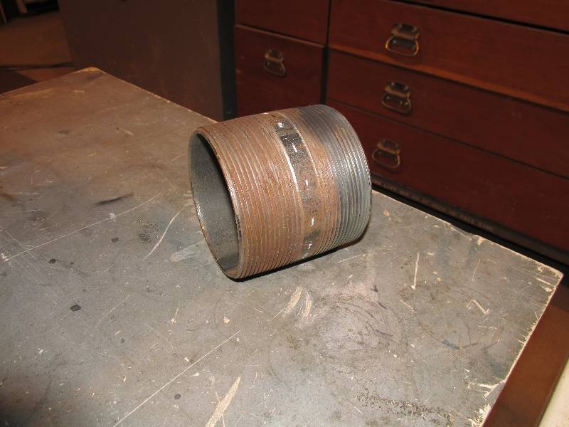
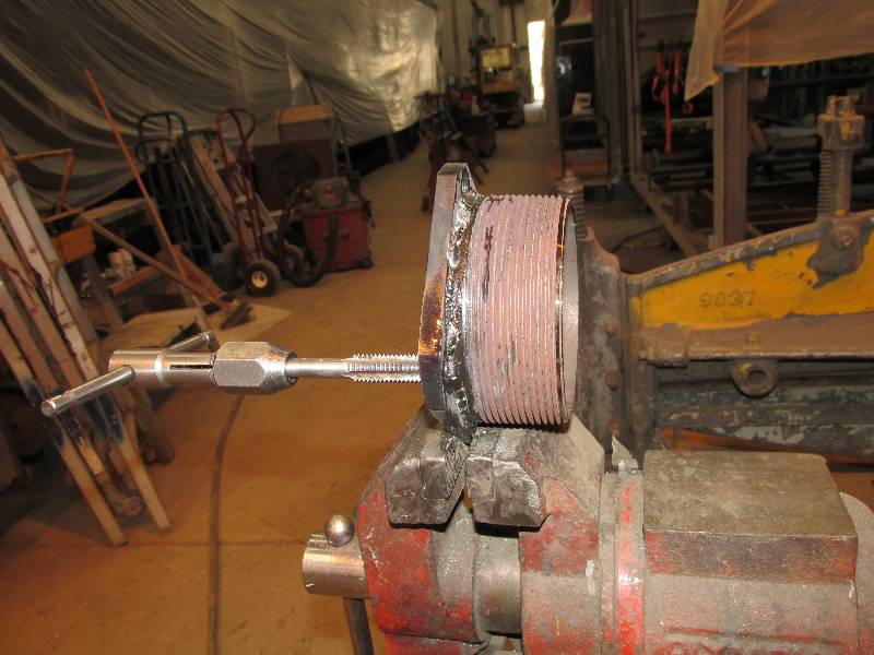
the mounting bases. A 4" pipe nipple that was located on Ebay was
cut in half and welded to a new mounting base. The assemblies
were painted and installed on the tank filler necks. The caps
will be painted the next time I have scarlet paint in the gun.
Return
To Main Page