Southern
Pacific 9010
Mechanical Work
Page 5
Page 5
-- Update January 14, 2018 --
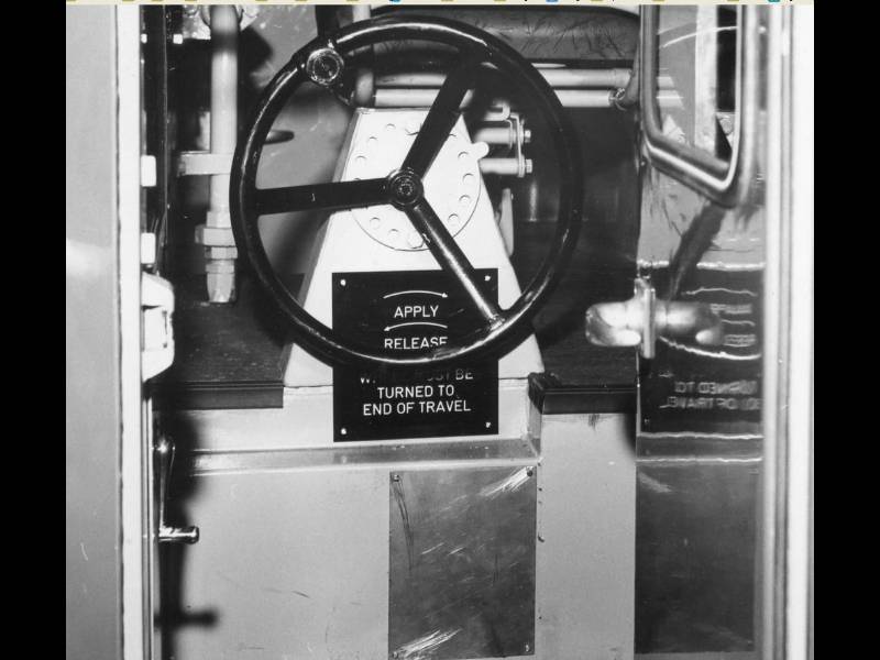
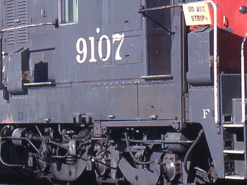
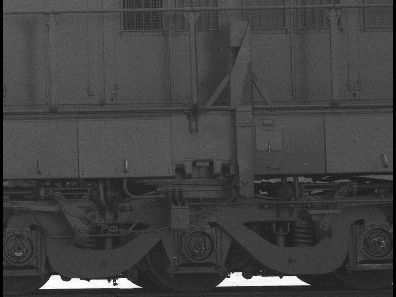
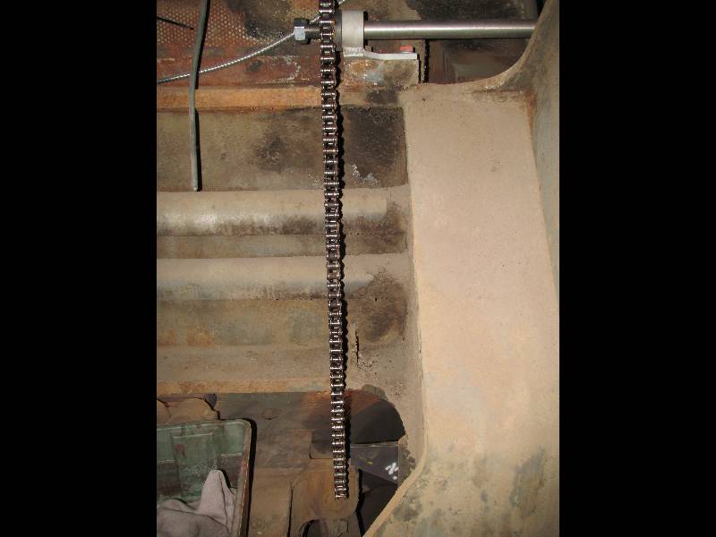
The 9010 was equipped with a hand brake located inside the cab, behind the fireman's seat. We do not know exactly why but in 1968, this mechanism was removed from the 9010 (and 4 other units) and a standard ratchet type brake installed on the right front end ahead of the cab (as seen on the 9107). The front end hand brake remained until the locomotives were scrapped. When our locomotive was converted into the Camera Car, the front hand brake had to go because there was no room for it beside the camera housing. The ratchet mechanism was moved to the left rear as seen in the 3rd photo. In order to have the brake on the rear end, some truck modifications were required but the truck we acquired from France did not have these added bits so, we decided that the locomotive needed have its original brake system restored.
 |
 |
 |
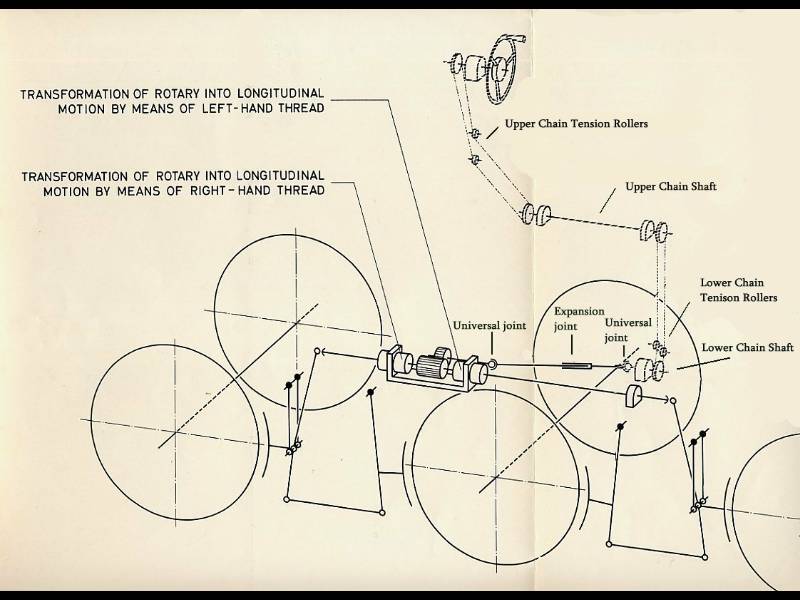
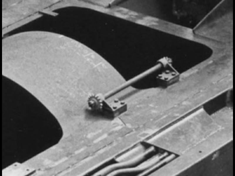
This drawing illustrates the original KM hand brake system. It consisted of 4 main sections, the cab brake wheel stand, upper chain shaft, expansion shaft and the truck mounted mechanism. With all the gears and chains seen in this drawing, it is easy to speculate that the brake was a maintenance headache, being exposed to road dirt and dust as it was.
 |
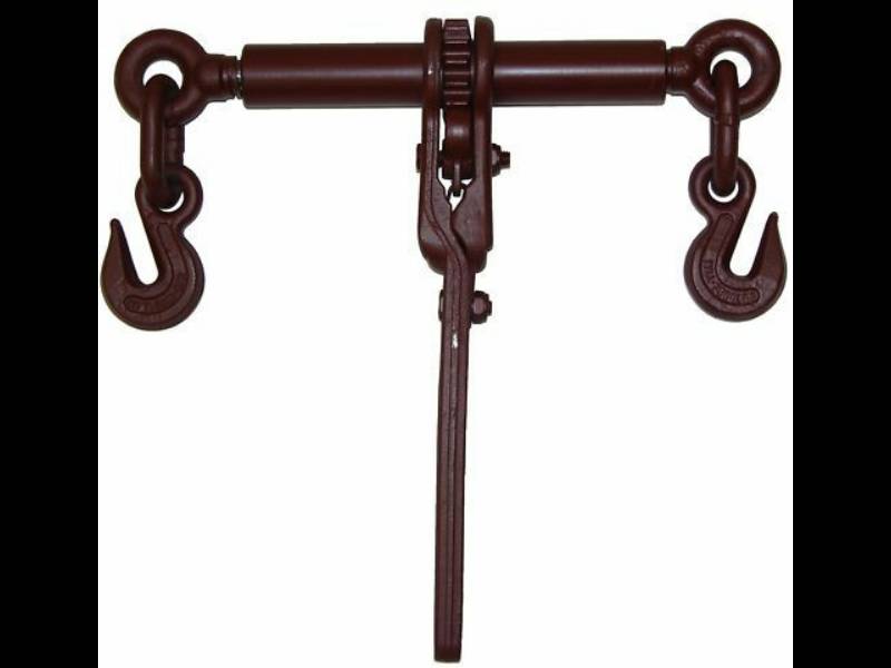
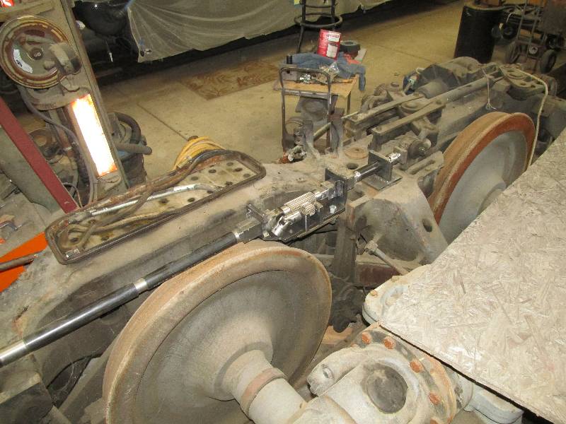
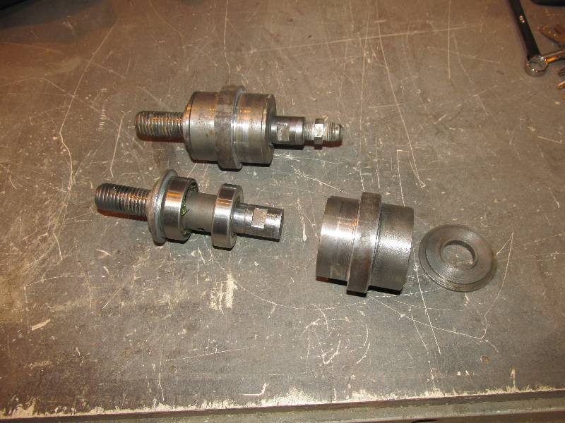
Bill, our project master
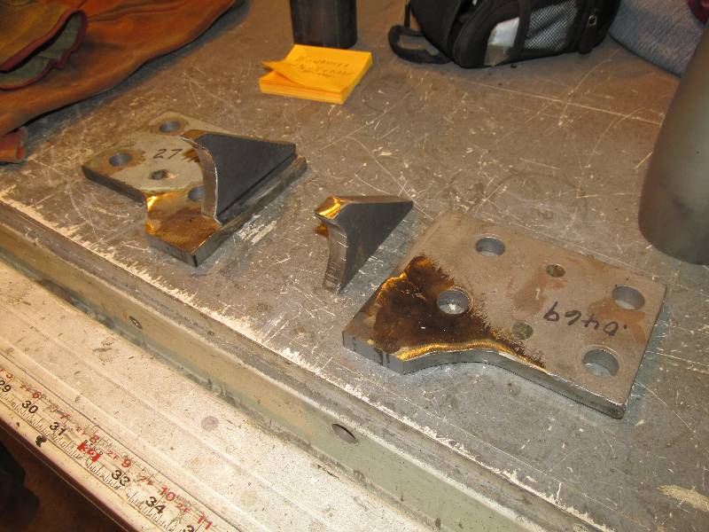
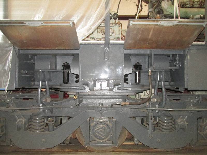
machinist, decided to start with the truck mounted mechanism as it is
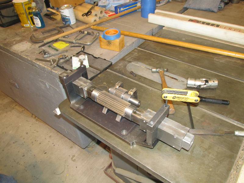
the most complex. The mechanism requires left and right
handed
Ajax threaded rods so we found a 16,000 pound rated chain binder on
Ebay and
started with it. He bought a section of gear and created the
assembly seen here. The opposing threaded rods will force two
of
the brake arms apart, applying the brakes on 3 wheels on the left side
of the front truck.
 |
 |
 |
 |
 |
 |
 |
 |
The expansion shaft connects the
truck mechanism to
the lower chain shaft bracket. It needs to have universal
joints
on each end and be able to expand and contract with the pivoting of the
truck.
 |
 |
 |
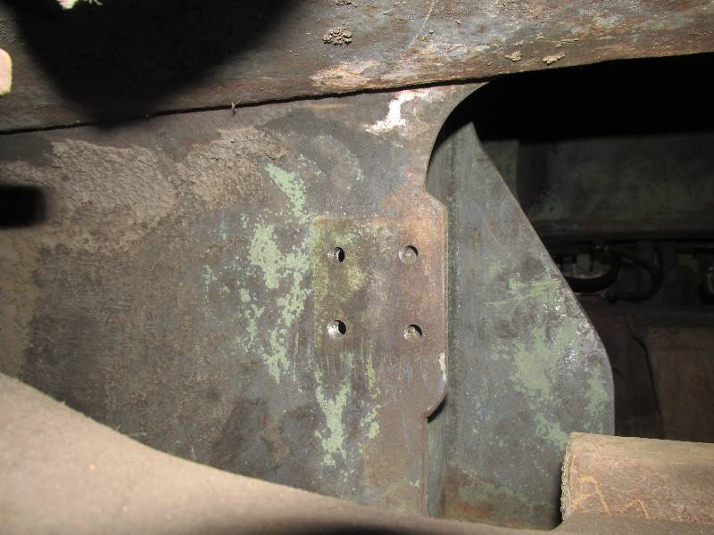
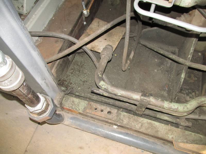
There was nothing of the the lower
chain shaft bracket other
than the 4 bolt holes and a shadow of the plate. Using those
dimensions and a photo of the bracket, Bill made the mounting plate and
bolted it into place. By hanging a piece of chain from the
upper
chain shaft sprocket, he was able to determine where the lower bearing
housing and sprocket needed to be. You may notice that the
original bearing housing had a grease fitting and our replacement does
not. This is because we are using two sealed ball bearings
rather
than the bronze sleeve bearing KM used. The same is true of
both bearing housings on the upper chain shaft.
 |
 |
 |
 |
 |
 |
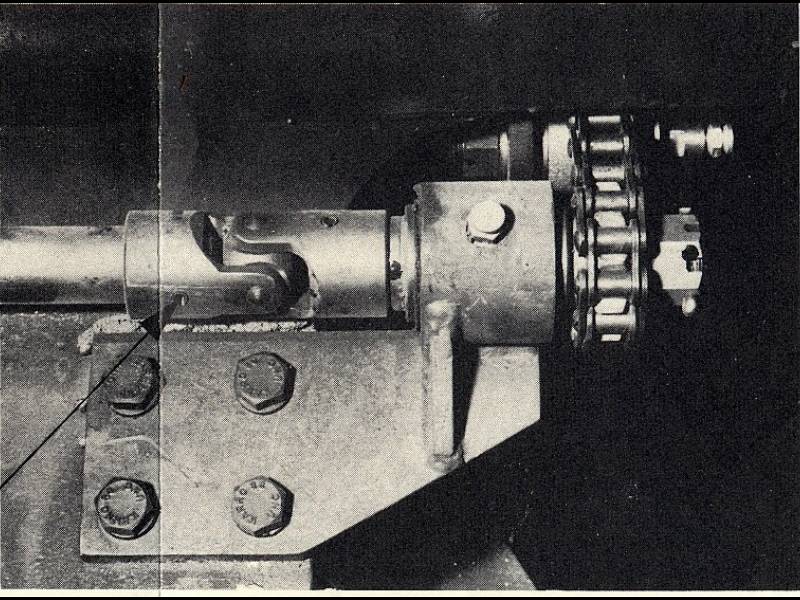
The Southern Pacific removed the upper chain shaft by torching off the bearing housings. For some reason they did not remove the bracket plates so we did and patched them to match the photos. After Bill made the bearing sleeves and gusset plates, everything was welded together to form the new brackets. He machined the shaft ends so the sprockets are keyed to the shaft and secured with aircraft nuts.
 |
 |
 |
 |
 |
 |
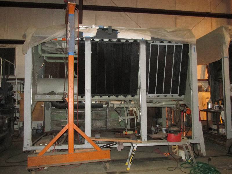
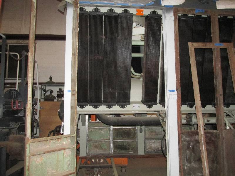
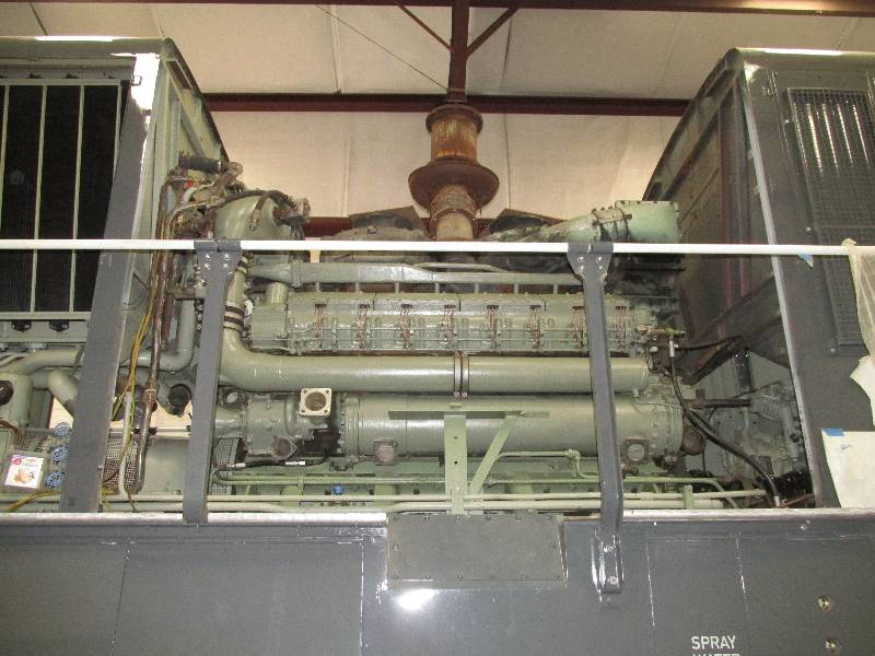
In other news, we now have 25 of
the 36
radiator elements built, tested, installed and tested again.
In
addition, the top tank sight glasses that were made to be cosmetic have
been re-made to be functional. Thanks to Bill and his
expertise
with our milling machine, they no longer leak. The red liquid
seen through the sight glass is an anti-corrosive compound from Nalco
that we use in our locomotives.
 |
 |
--
Update February 01, 2018 --
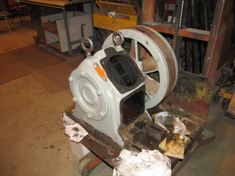
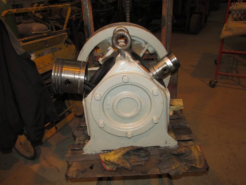
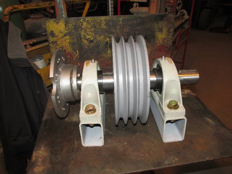
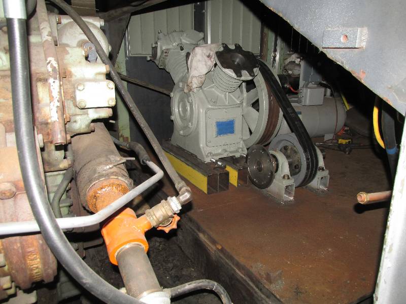
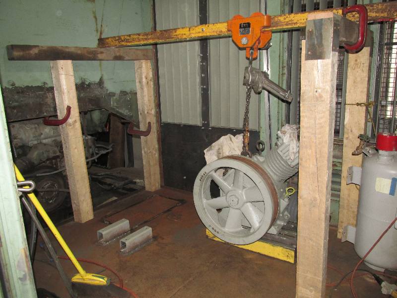
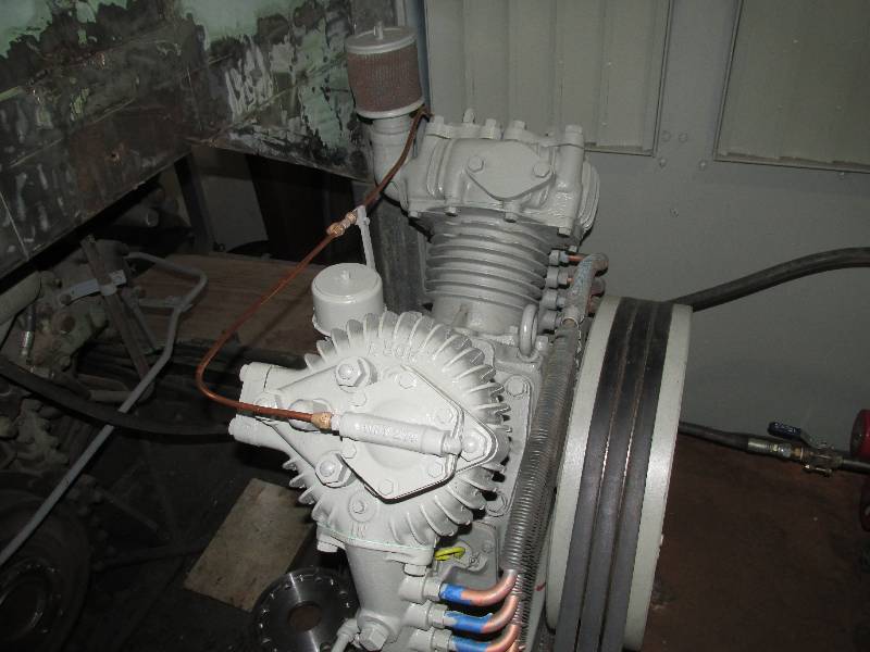
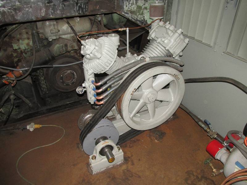
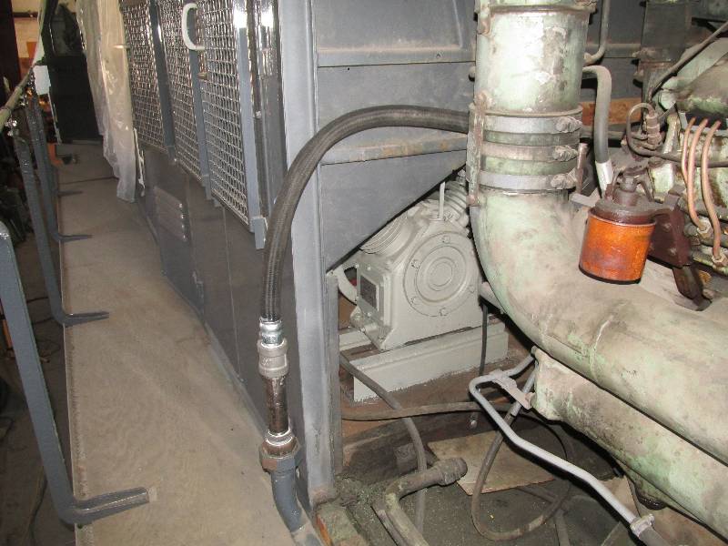
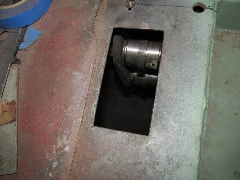
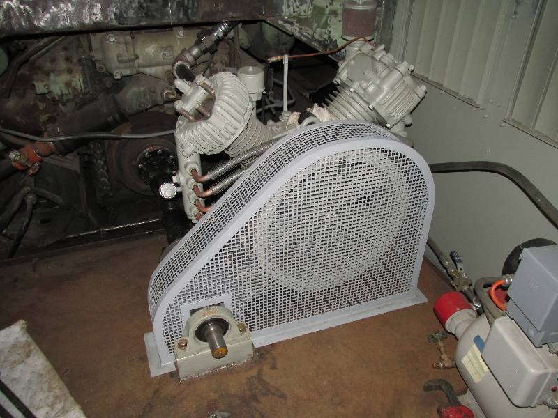
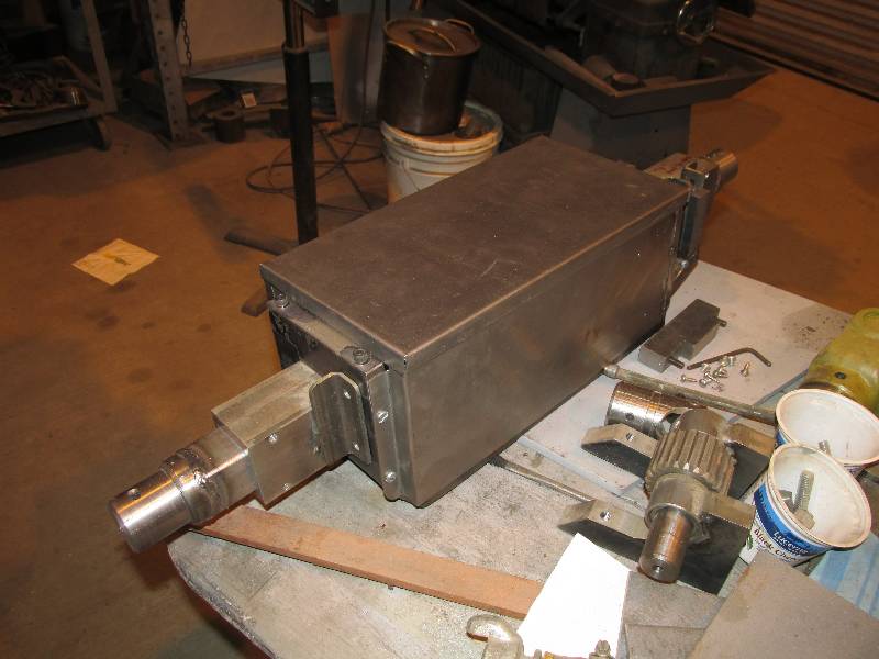
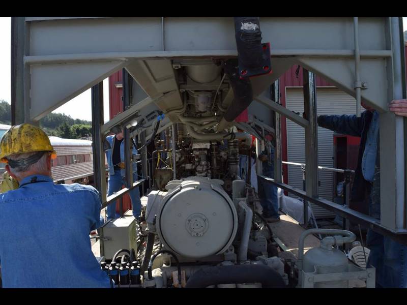
Work is progressing on the air compressor and its drive. We purchased a rebuild kit which includes gaskets, piston rings, inlet and outlet valves and bearings. Both cylinders were honed to clean them and provide a good surface for the new rings. Once the pistons, rods and cylinders were re-installed, the compressor was hoisted into the equipment room. The drive pulley assembly is shown in position relative to the compressor and the engine crankshaft coupling.
Work is progressing on the air compressor and its drive. We purchased a rebuild kit which includes gaskets, piston rings, inlet and outlet valves and bearings. Both cylinders were honed to clean them and provide a good surface for the new rings. Once the pistons, rods and cylinders were re-installed, the compressor was hoisted into the equipment room. The drive pulley assembly is shown in position relative to the compressor and the engine crankshaft coupling.
 |
 |
 |
 |
 |
 |
 |
 |
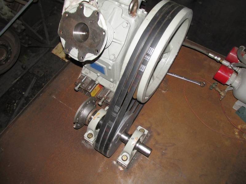
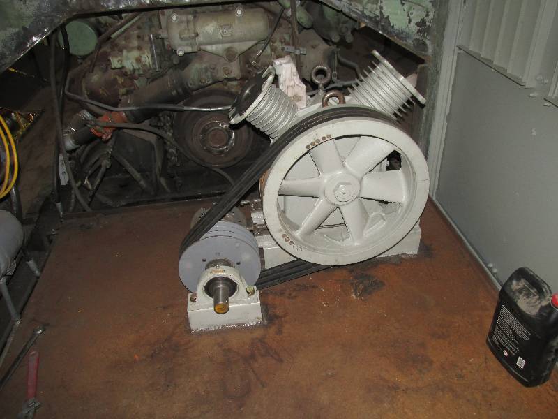
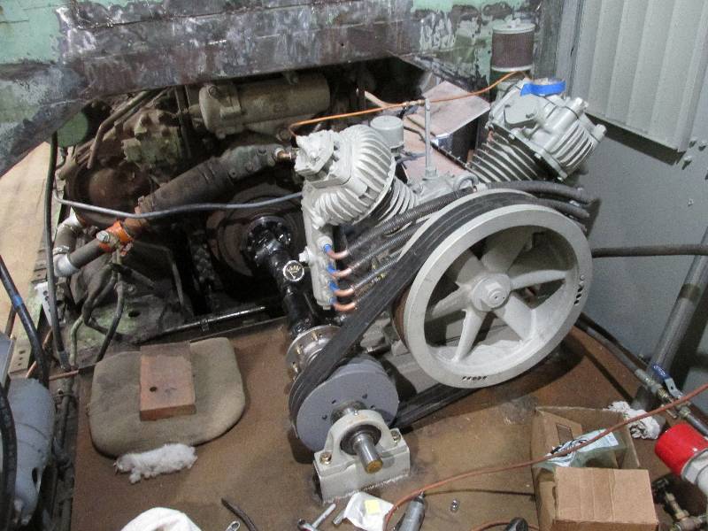
After locating the drive pulley
assembly in line with the Maybach crankshaft and centered on the floor,
I welded its feet to the floor. Bill insured that the two
pulleys were parallel with each other and the grooves
aligned so the belts would track correctly.
 |
 |
 |
 |
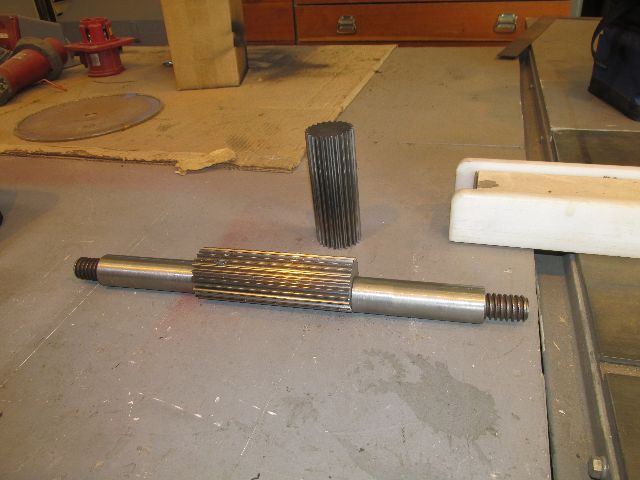
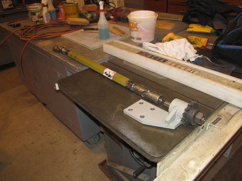
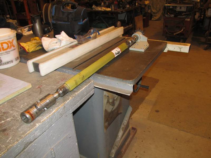
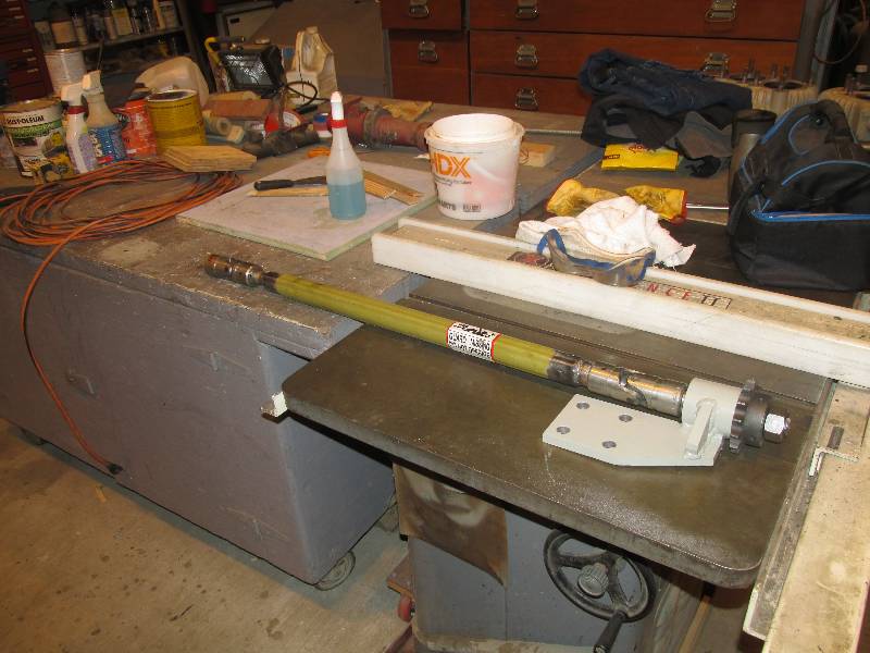
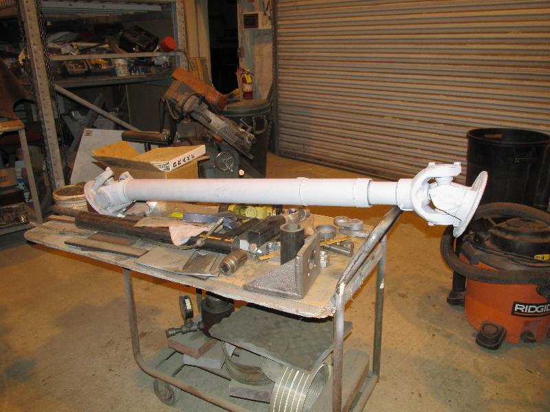
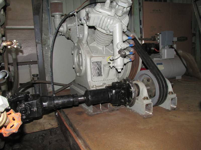
We acquired a drive shaft from a
Spicer drive on a passenger car. It was originally used to
drive the battery charging generator but will have a new life driving
our compressor and hydraulic pump. Bill overhauled the shaft
and is sending it out to be shortened and balanced. This will
be the last major piece of the compressor saga. We
subsequently
discovered that the shaft would not balance because the internal
splines were worn out. So, we bit the bullet and bought a new
shaft but the shop was able to use the old flanges which eliminated any
re-machining of our driving plates.
 |
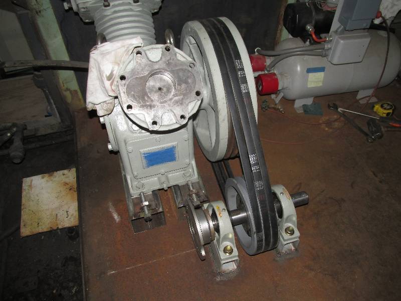
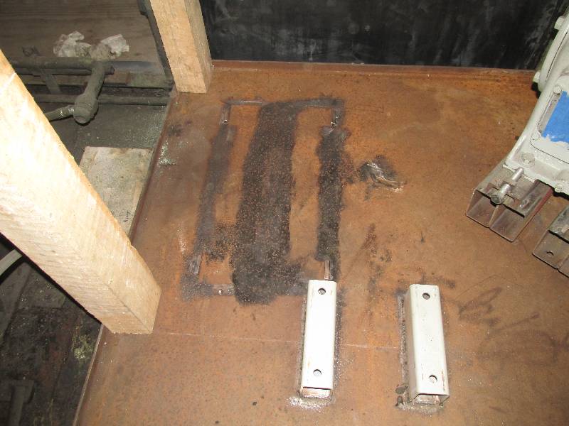
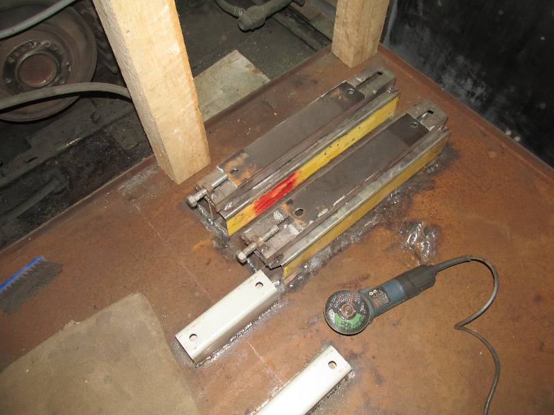
Meanwhile back in the compressor
room, we had to move the compressor out of the way in order to weld its
mounts to the floor. I welded some small pieces of square
tubing
next to the mounting feet in order to locate them. The
compressor was moved, the
floor prepared for welding and the compressor was re-positioned and
checked for alignment. When all
seemed good, I tack welded the mounts to the floor, unbolted
the compressor from the mounts and moved the
compressor out of the way. Then started a couple hours with
the
MIG, the mounts and the floor.
 |
 |
 |
 |
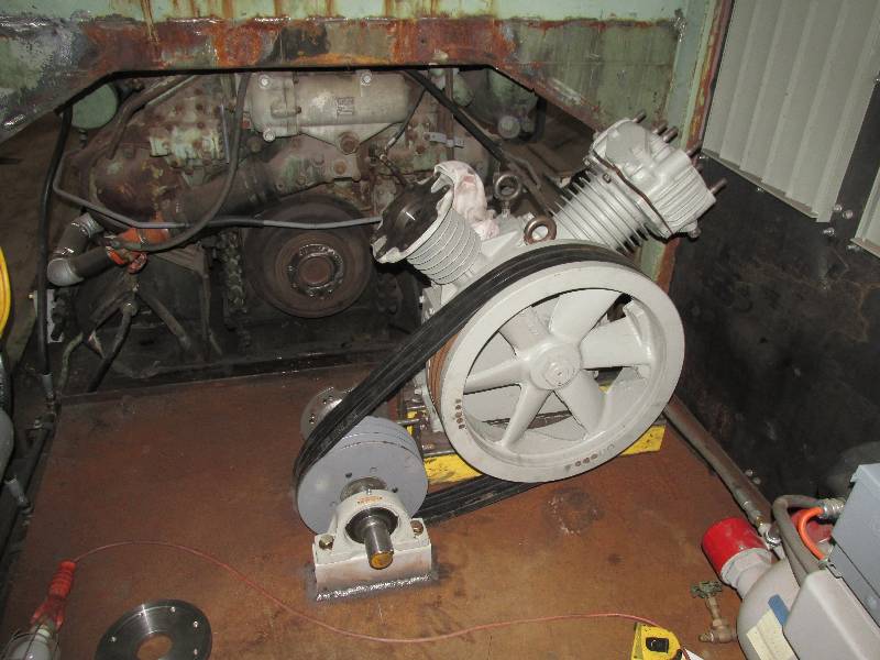
While the compressor was out of
the way, I
cleaned and painted the inside wall below the pair of shutters.
Once all the welding was done, the compressor was
put back, bolted it down to its mounts and the belts were
tightened. A few days later the cylinder heads, valves,
intercooler pipe assembly and unloaders were installed. Bill
made an adapter plate for the engine crankshaft accessory
drive coupling which we installed followed by the custom made drive
shaft. Finally, the unloader control line was connected.
All
that is left now is connecting the air output line.
Oh yes, and making nice legal covers
for the belts and shafts. There is a short video of the
compressor being turned by the engine HERE.
 |
 |
 |
 |
 |
 |
 |
 |
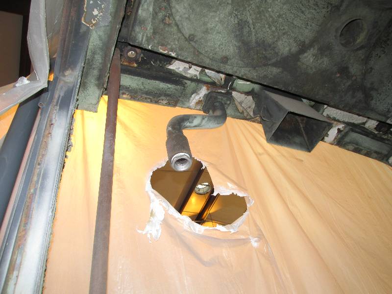
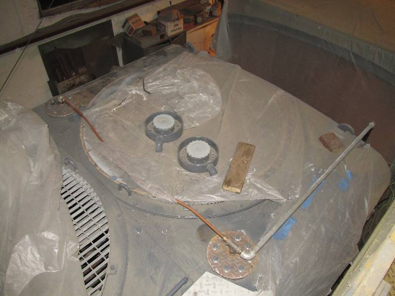
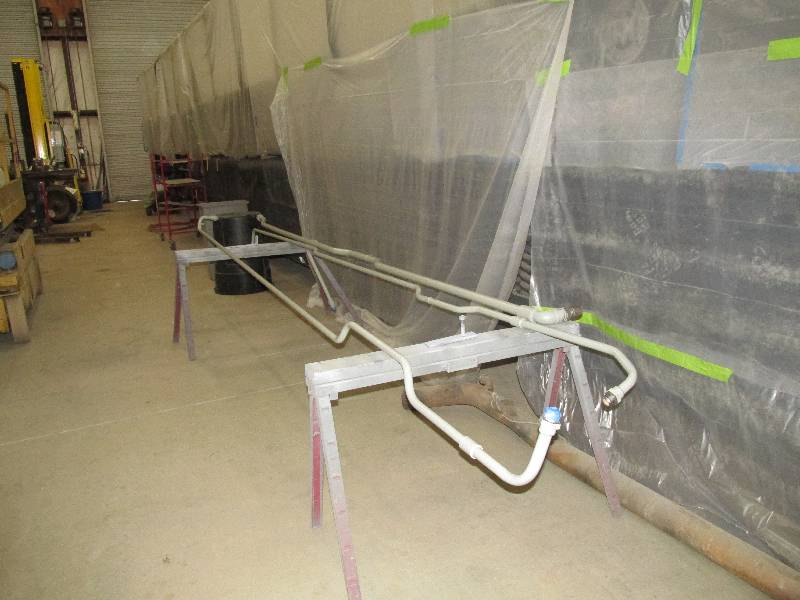
The outlet of the air compressor
normally goes to the
pipe seen in photo #1. This pipe leads to the roof-mounted
cooling pipes. Because the engine hood is off, we
temporarily connected the compressor to the cooling pipes frame
connection.
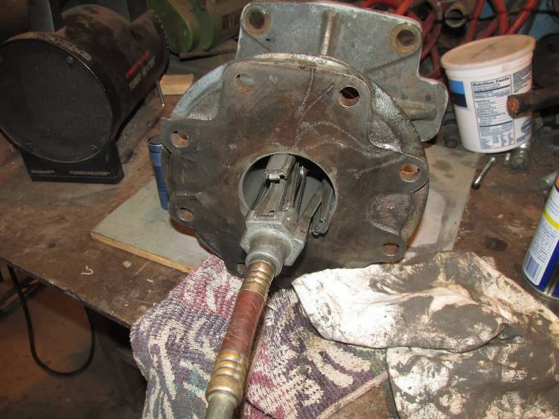
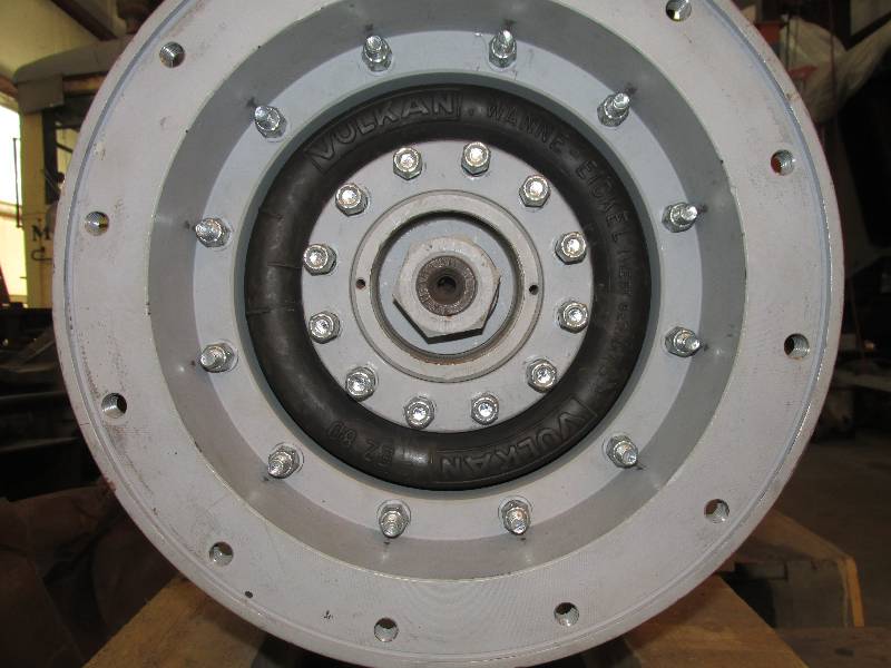
The last time we started the Maybach engine, Bill noticed that there was a vibration in the dynastarter. Some investigation led us to believe that it was caused by the rubber coupling between the dynastarter and the transmission. We found that the dynastarter coupling hub was running around .035 out of round. We have no technical data on the setup of the coupling but theorized that the coupling bolts may have been unevenly tightened, causing the rubber coupling parts to deform. We loosened all of the bolts, jiggled the coupling hub around a bit and then torqued all of the bolts to 23 foot pounds, the correct torque for the bolts. Upon checking the hub with the dial indicator, we found that the hub was now only .009 our of round so we put the dynastarter back on the transmission and started the engine. The vibration was now nearly gone and when we revved the engine slightly, the vibration went completely away. We decided to leave well enough alone for now and will continue to check the vibration as we test the locomotive.
 |
 |
 |
The last time we started the Maybach engine, Bill noticed that there was a vibration in the dynastarter. Some investigation led us to believe that it was caused by the rubber coupling between the dynastarter and the transmission. We found that the dynastarter coupling hub was running around .035 out of round. We have no technical data on the setup of the coupling but theorized that the coupling bolts may have been unevenly tightened, causing the rubber coupling parts to deform. We loosened all of the bolts, jiggled the coupling hub around a bit and then torqued all of the bolts to 23 foot pounds, the correct torque for the bolts. Upon checking the hub with the dial indicator, we found that the hub was now only .009 our of round so we put the dynastarter back on the transmission and started the engine. The vibration was now nearly gone and when we revved the engine slightly, the vibration went completely away. We decided to leave well enough alone for now and will continue to check the vibration as we test the locomotive.
 |
 |
Dee has been very busy with the
needle gun, other various tools and paint. She has completed
the cleaning of all 8 of the friction damper (shock absorber) mounting
areas, has painted the areas and re-installed all 8 of the dampers.
This was a lot of work and she has done a wonderful job.
She is now working on the cleaning of the left front truck,
preparing it for painting.
 |
 |
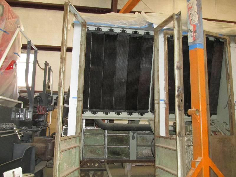
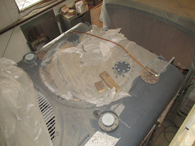
We have also installed more
radiator elements. On 02/13/18, we needed 5 which
were 1 in
the primary cooling system and 4 in the secondary system.
Today
(02/20/18) Rich A. delivered 2 and one was dutifully installed in the
blank spot seen in photo #1. We have now installed all 28
elements in the primary system. Once this is hydro-tested one
more time, I will move the vent piping to the secondary
system
and start testing it.
 |
 |
 |
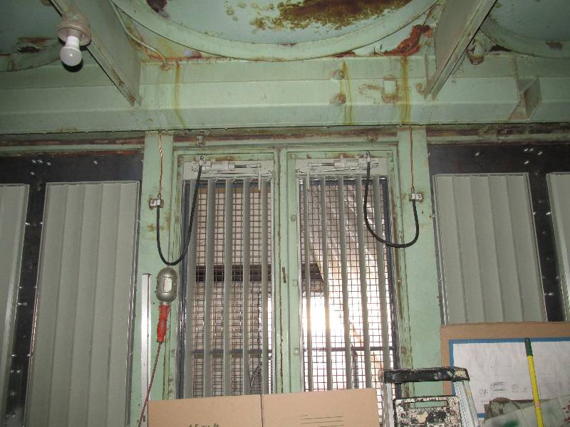
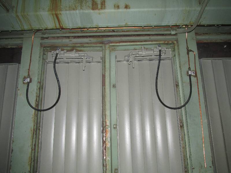
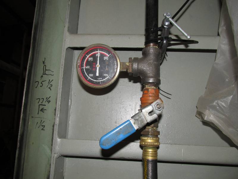
We decided to connect the 4 four
real shutters on the number 1 cooling hood. The shutters were
originally controlled by the hydraulic fluid pressure going to the
cooling fans but since there are no fans (and no #1 hydraulic system)
we connected the shutter air supply through a simple valve mounted on
the door frame.
 |
 |
Work has not stopped on the hand
brake. Among
other things, the upper chain guide roller assemblies were cleaned and
the guide surfaces were narrowed slightly because of the difference in
the width of the original metric chain roller and the #60
chain
we have. After assembly, they were re-installed under the cab
floor, where they are pretty hard to see.
 |
 |
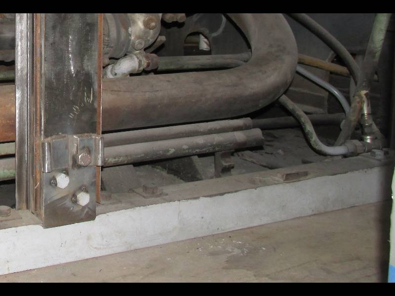
The replacement lower chain
tension device was welded into place on the frame. The
original was removed by the SP. The chain will not be
installed until the brake mechanism is mounted on the truck.
 |
After a final successful
hydrostatic test of the 28 primary cooling system elements, I moved the
vent piping from the primary to the secondary cooling system.
Five of the eight elements are already installed and an
initial hydrostatic test was 100% successful so we now need to wait for
the last 3 radiators.
 |
 |
 |
--
Update April 01, 2018 --
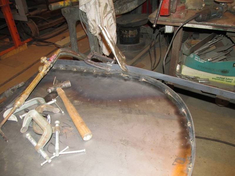
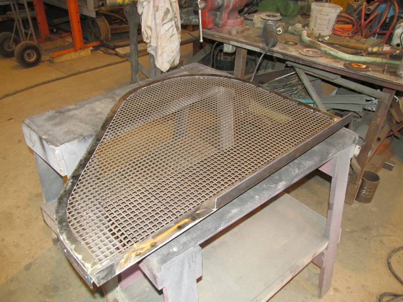
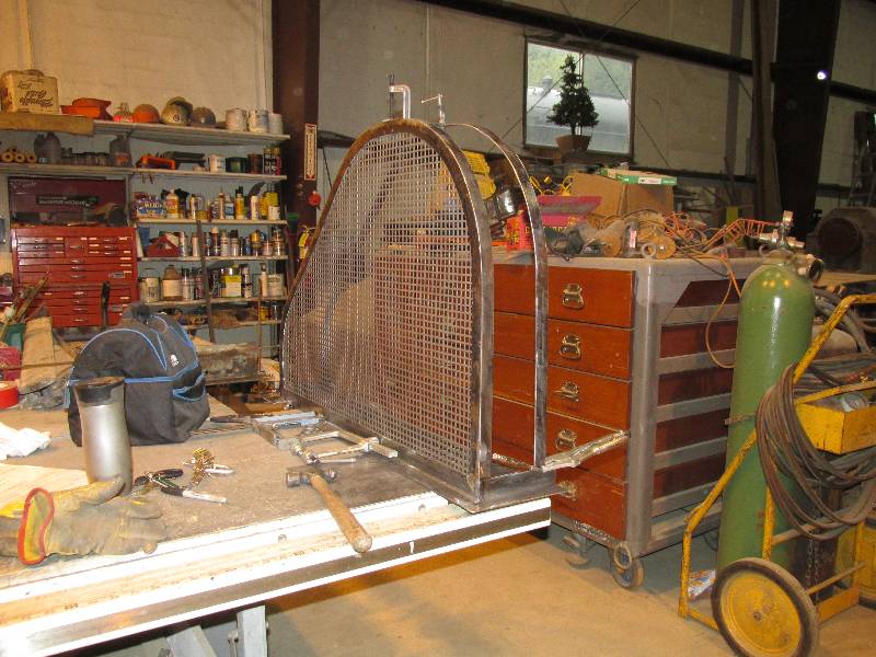
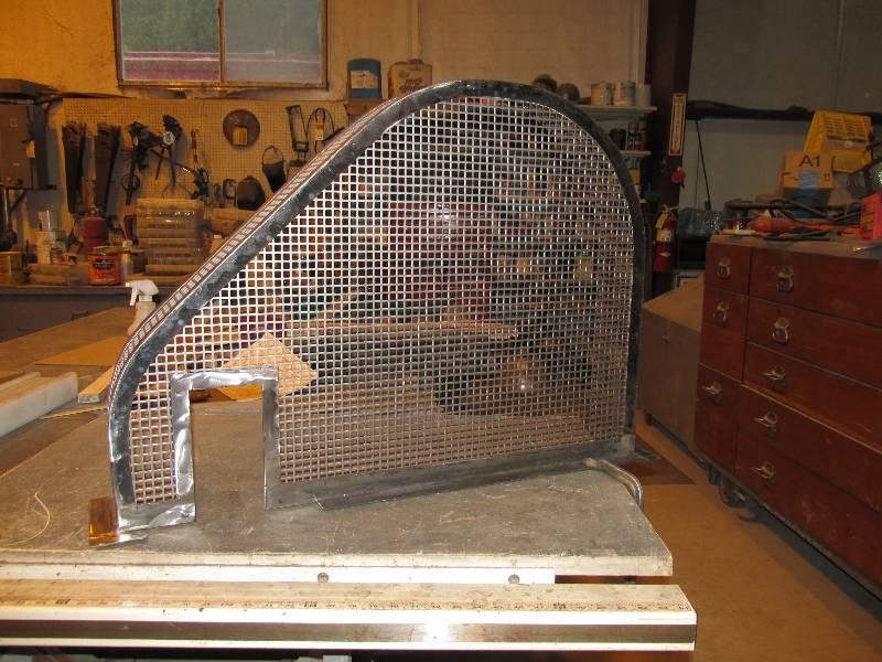
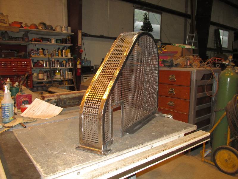
Federal law requires that all rotating equipment have protective covers. We already built one for the cardan shaft between the engine and transmission and now our attention turned to the air compressor. There are actually 2 covers required, one for the belt drive and another for the shaft drive. Here in photos is the construction of the belt drive cover.
Federal law requires that all rotating equipment have protective covers. We already built one for the cardan shaft between the engine and transmission and now our attention turned to the air compressor. There are actually 2 covers required, one for the belt drive and another for the shaft drive. Here in photos is the construction of the belt drive cover.
 |
 |
 |
 |
 |
 |
 |
 |
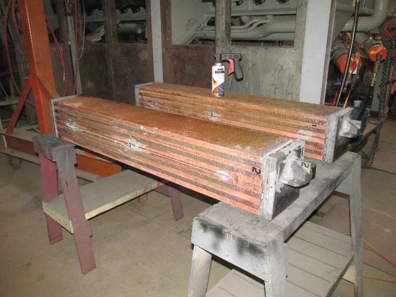
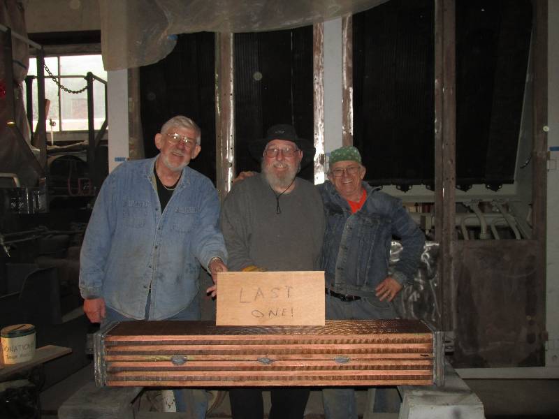
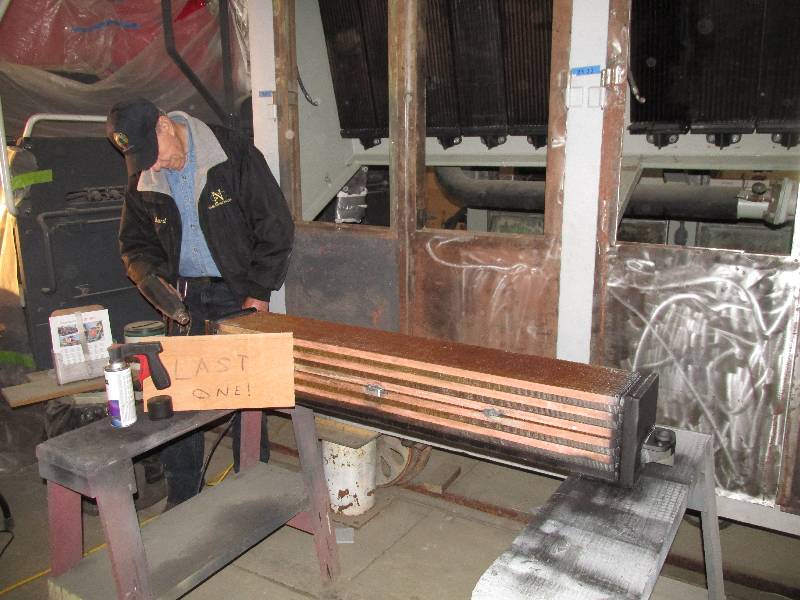
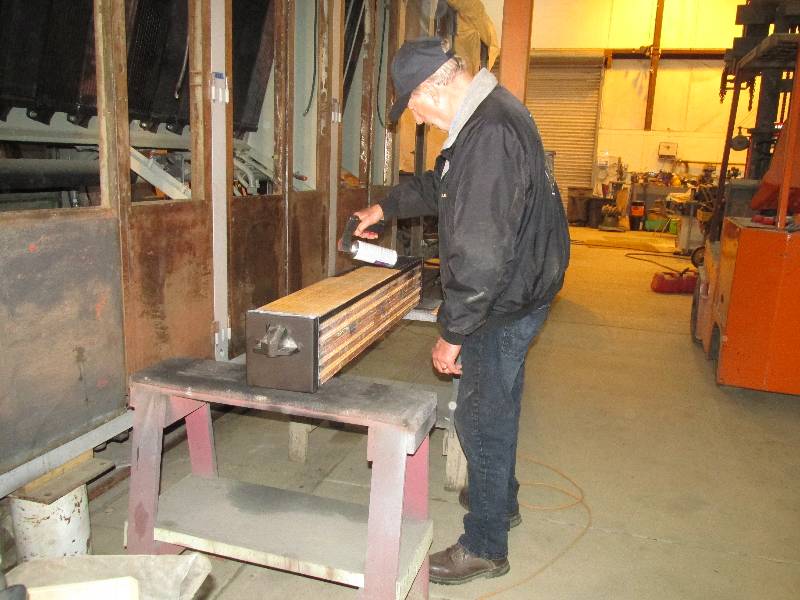
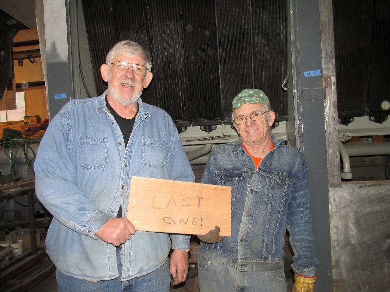
On Tuesday March 20,
we completed an extensive and very expensive part of the project.
Rich Alexander delivered the last of our 36 radiator
elements. Bill, Rich and I pose with a hastily made sign
marking the event. Rich Anderson helped out by drying the
element (it was a rainy day) and painting it.
After the install, Bill and I congratulate ourselves on the
moment. On Thursday the 22nd, we did the final hydrostatic
test of the cooling group, holding 25 psi of water pressure for an hour
with no leaks.
 |
 |
 |
 |
 |
 |
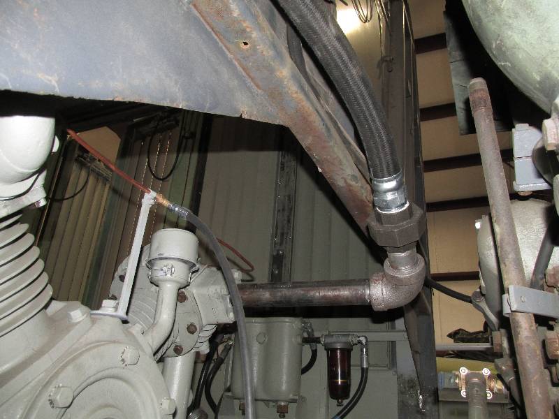
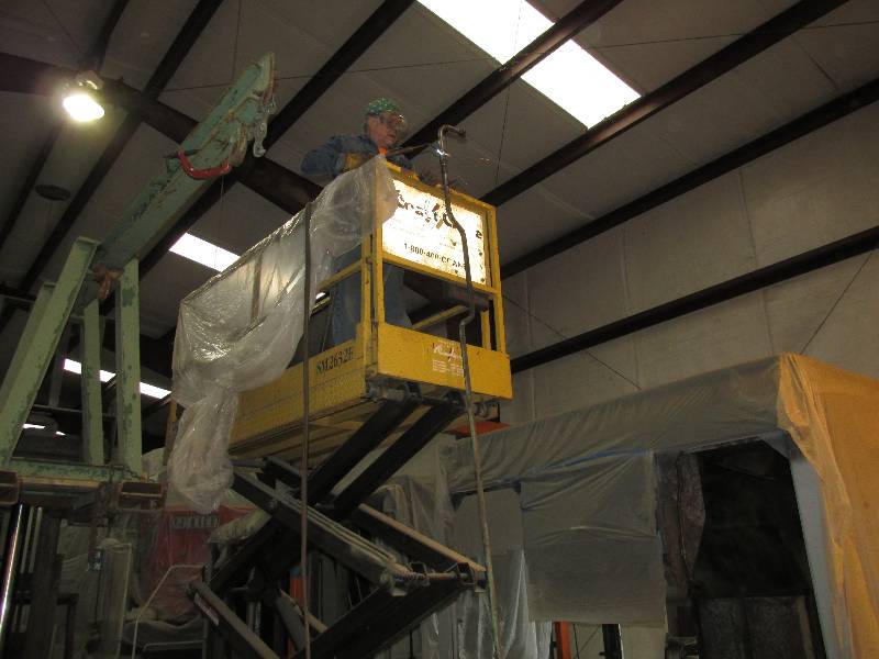
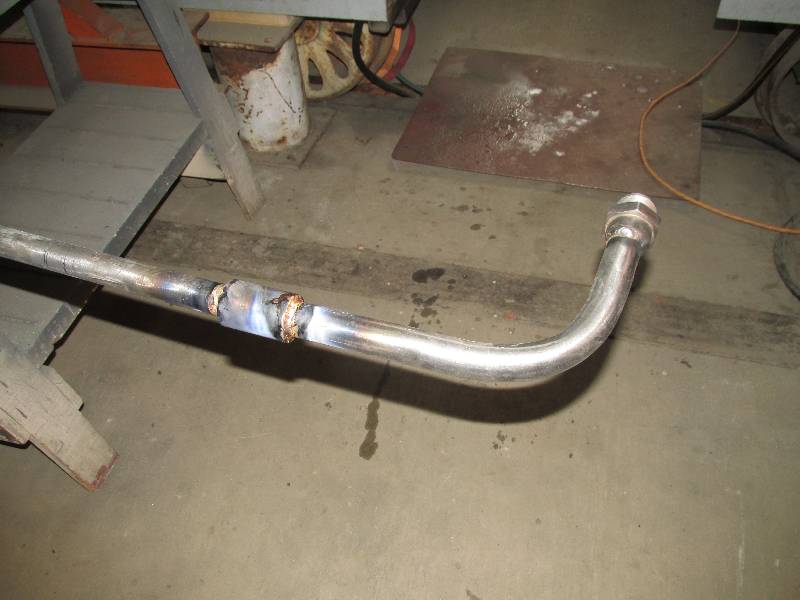
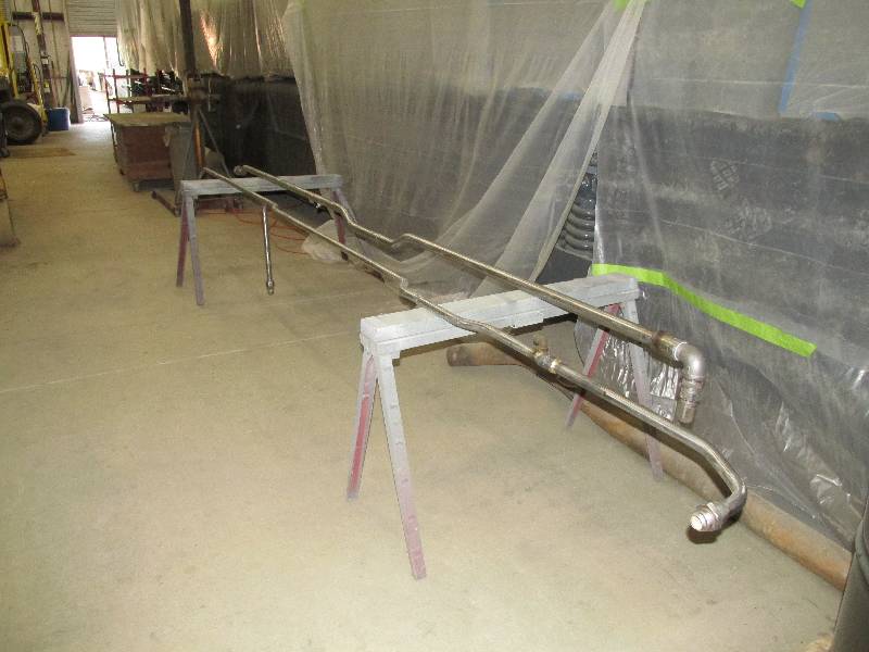
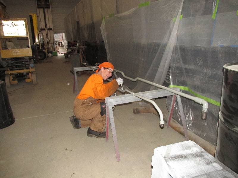
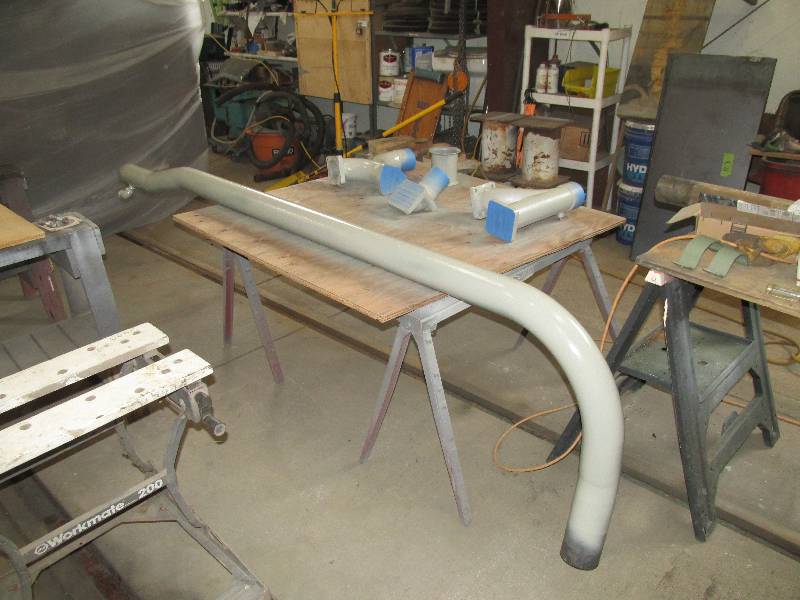
We are also repairing 3 of the 4 hydraulic lines (2 on each side of the engine) that connected the pump system to the radiator cooling fans. These lines were cut by the Southern Pacific during the camera car conversion. One of the cut lines carrys nearly 3000 pounds of hydraulic pressure so after joining the line with a repair end, the coupling was brazed on both ends. Due to the length of the pipe and the desire to have the brazing material flow down into the threaded coupling. I hoisted the piping into the air with our scissor lift so it would be vertical. Dee helped on the project with her usual fine job of cleaning and painting.
 |
 |
 |
 |
 |
 |
 |
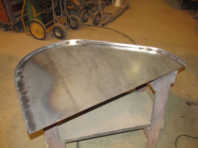
Bill continues his
work on the new
hand brake mechanism. Because the complex part of the system
is
located above and in front of the center driver in the truck, he
decided that the mechanism should have a cover. We wonder if
this
exposure to the elements may have been part of the reason for
the
demise of the original handbrake installation.
 |
 |
--
Update May 14, 2018 --
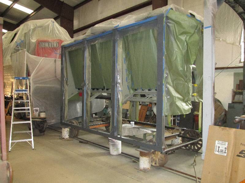
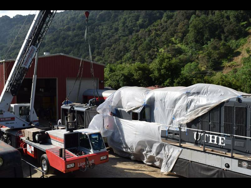
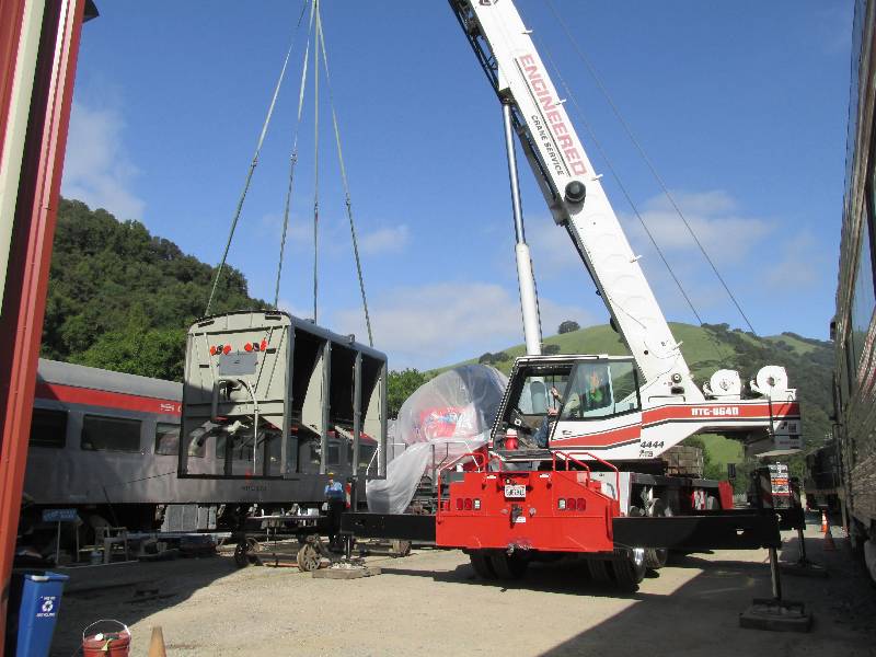
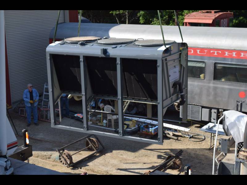
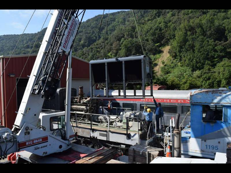
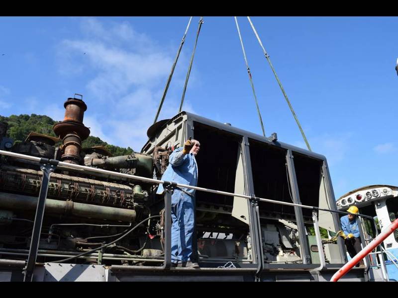
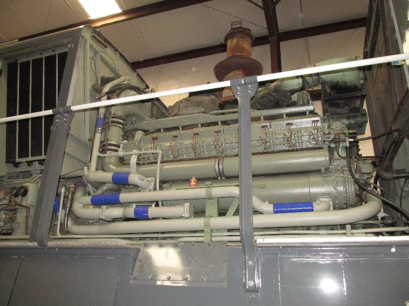
After a bit more work on the #2 cooling hood, which included repainting the top and door posts, the hood was re-installed on the 9010's frame. Ed of Engineered Crane Services did a fantastic job for us.
After a bit more work on the #2 cooling hood, which included repainting the top and door posts, the hood was re-installed on the 9010's frame. Ed of Engineered Crane Services did a fantastic job for us.
 |
 |
 |
 |
 |
 |
 |
 |
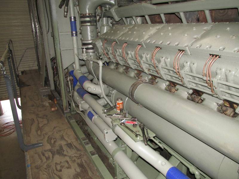
We had not thought
about painting the engine block at this point but Dee convinced me that
she could take on the job and get it done in a timely manner.
Needless to say, she did.
 |
 |
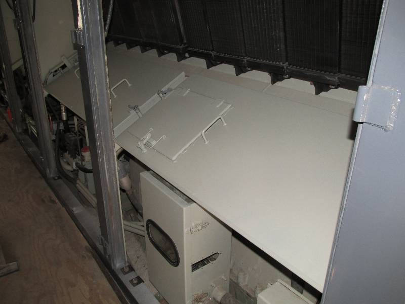
Each of the six
radiator sections had a cover that prevented dirty air from passing
from under the locomotive and through the radiators. All but
one of ours were missing so we had Melrose Metals make 6 new.
We are also cleaning and painting all of the water piping
that connects the engine to the cooling hood. By the way, the
small hinged cover in the second photo is for access to the
transmission dip stick.
 |
 |
 |
 |
--
Update June 06, 2018 --
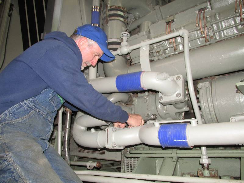
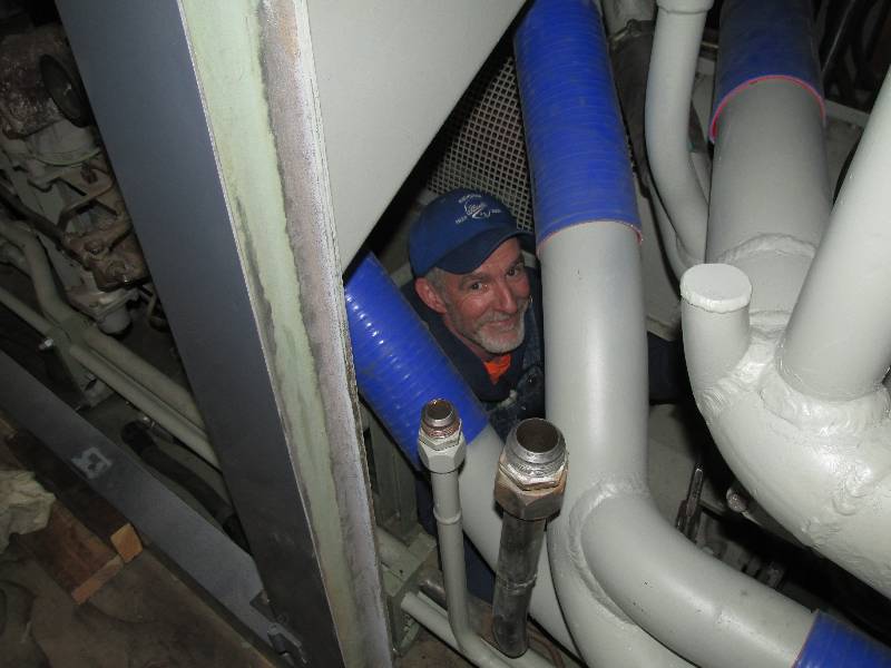
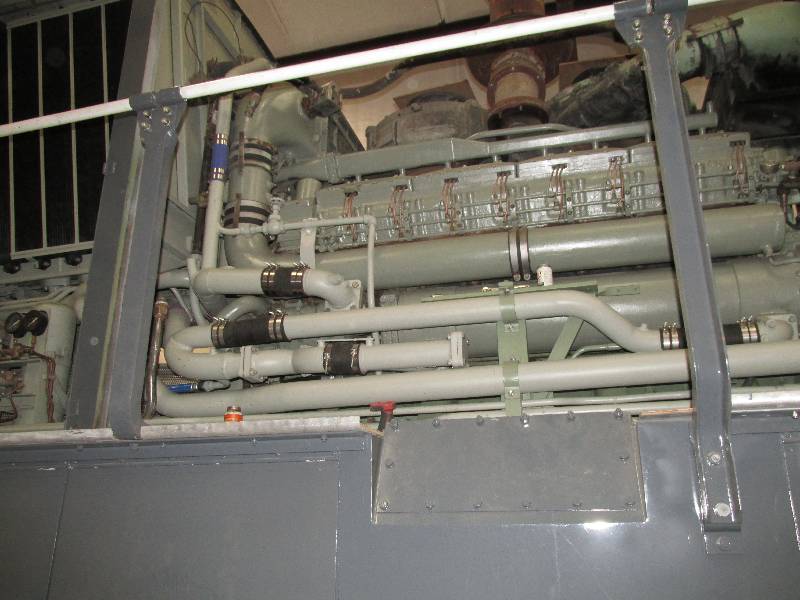
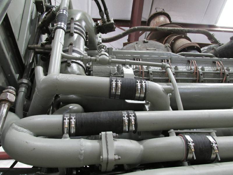
Re-installing the water piping became a priority, not only to have the system back together but to get all the parts off the shop floor and back where they belong. It took a few working days and welcome help from my son Brian to get all of the engine water pipes properly placed and connected with new hi-tech silicone hose. Brians help and mechanical ability was deeply appreciated. Brand new stainless steel hose clamps came next.
Re-installing the water piping became a priority, not only to have the system back together but to get all the parts off the shop floor and back where they belong. It took a few working days and welcome help from my son Brian to get all of the engine water pipes properly placed and connected with new hi-tech silicone hose. Brians help and mechanical ability was deeply appreciated. Brand new stainless steel hose clamps came next.
 |
 |
 |
 |
Although I kind of
like the look of the blue silicone hoses, they don't look right with
the Maybach engine. Dennis Mann came up with the brilliant
idea of wrapping them with black friction tape which improved their
appearance massively.,
 |
 |
Return To Main Page