Southern
Pacific 9010
Mechanical Work
Page 8
Page 8
--
Update February 16, 2021 --
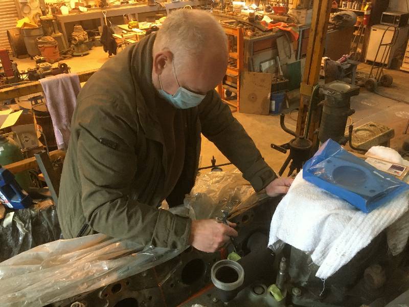
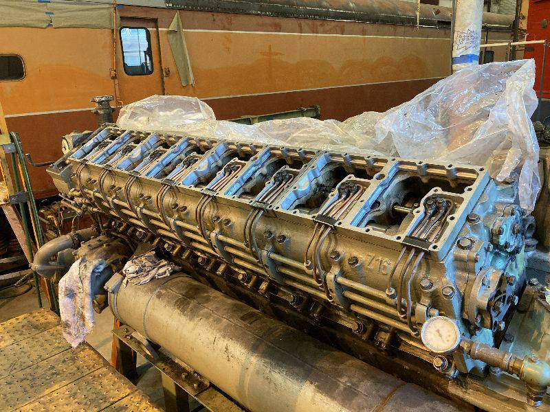
Bill set to work installing the piston crowns and crush rings on the right side of the block. The crowns are equipped with the compression rings and the crush rings are what seal the heads to the block. A crush ring can be seen in the last photo, surrounding the piston crown. When all 8 cylinders were finished, Bill and I torqued the head bolts.
Bill set to work installing the piston crowns and crush rings on the right side of the block. The crowns are equipped with the compression rings and the crush rings are what seal the heads to the block. A crush ring can be seen in the last photo, surrounding the piston crown. When all 8 cylinders were finished, Bill and I torqued the head bolts.
 |
 |
 |
 |
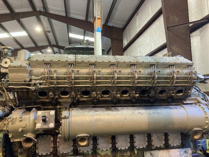
Once Bill finished,
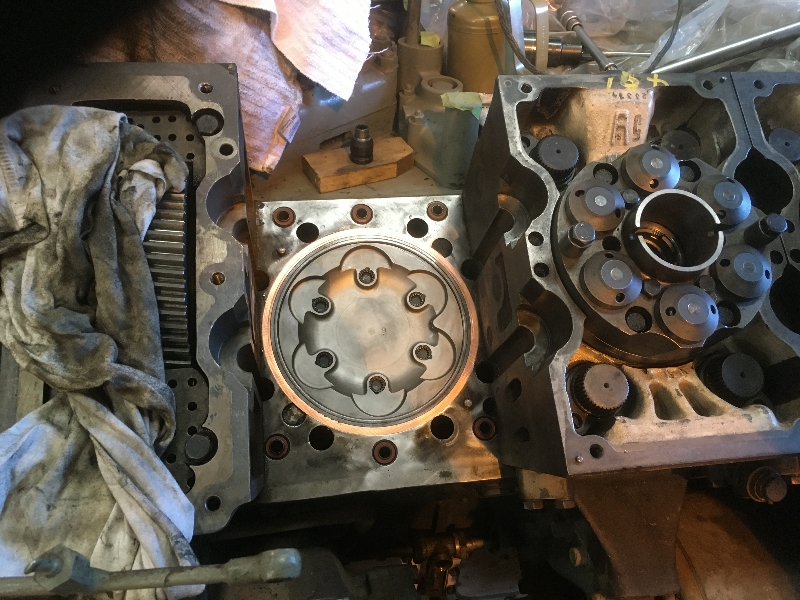
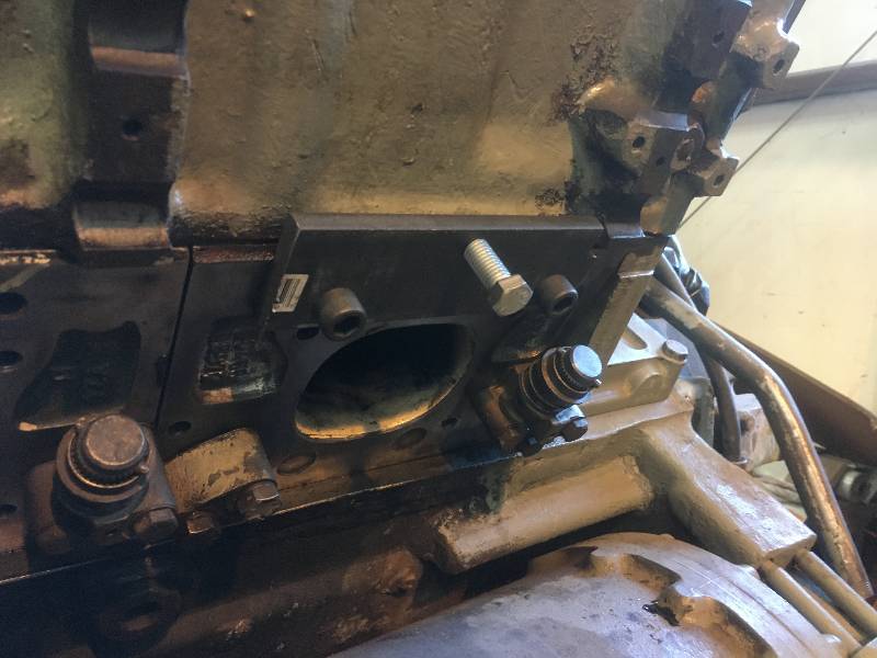
Karl installed the exhaust elbows on the right side. Four
cylinders on each side feed one turbocharger. This is to say
that cylinders 1, 2, 3,4 ,9 ,10 ,11 and 12 feed the rear turbo while
cylinders 5, 6, 7, 8, 13, 14, 15 and 16 feed the front turbo.
Each of the turbos only has 6 inlets on its bottom so 2
cylinders of each group are siamesed as shown by the last photo.
 |
 |
 |
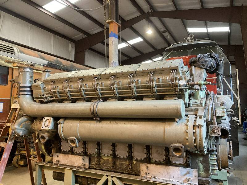
When Karl finished,
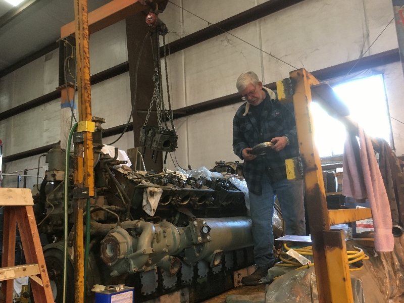
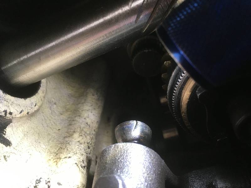
Bill and I installed the right side cam box. This is a very
heavy cast assembly that is difficult to handle. It must be
settled into the correct place so that there is proper spacing between
the injector lay shaft and the top of an injector. We created
a pair of adjusting plates that allowed proper positioning of the cam
box (photo 3) Lacking the special measuring tool (photo 2), we simply
installed an injector on each end of the engine and insured that there
is some free movement between an injector gear and the lay shaft gear.
 |
 |
 |
 |
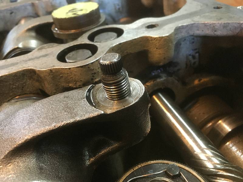
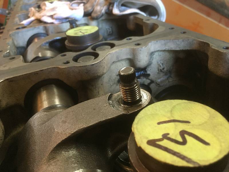
Next came injector
installation which was covered in a much earlier update (mechanical 4),
before we ran the engine. One of the adjustments requires
that the adjusting screw be turned as far out as possible which
provides the starting point for the adjustment. At this
point, there should be some clearance between the adjusting screw and
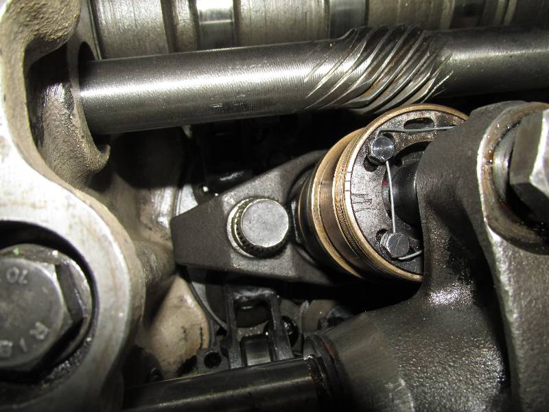
the short push rod that rides in the injector. Cylinder #13
would not cooperate. Photo # 1 is cylinder #13 and photo #2
is cylinder #15. It can be seen that the screw on #15 is
higher that the other one. After much head scratching, it was
determined that the end of the screw on #13 was broken and could not
fit inside the rocker arm, thus preventing its movement upwards.
After the broken screw was extracted, it became clear that
the cupped end of the screw had broken somehow.
 |
 |
 |
 |
With all the previous
work out of the way, we installed the injector frames, injector fuel
lines and the intake manifold. Finally, Bill and I moved the
work
platform to the left side of the engine where it first was in July of
2019 when engine disassembly began.
 |
 |
 |
 |
--
Update May 25, 2021 --
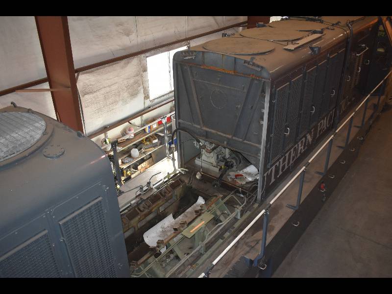
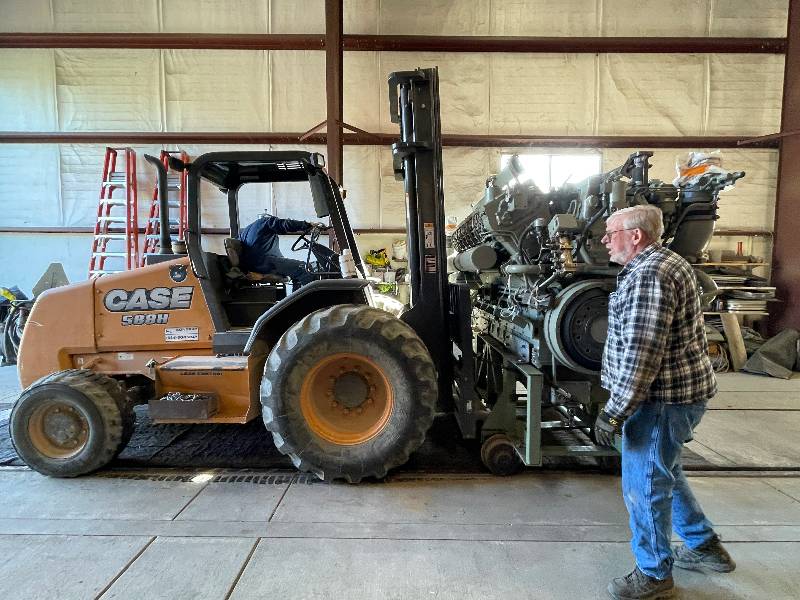
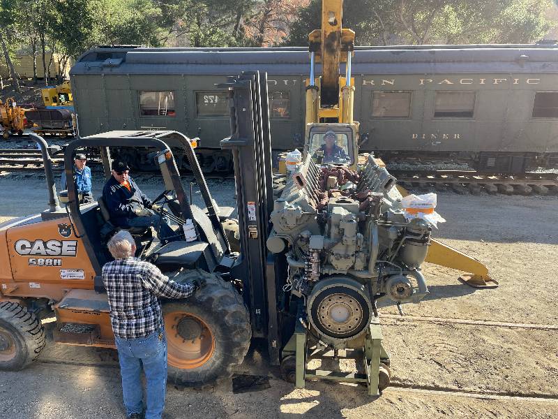
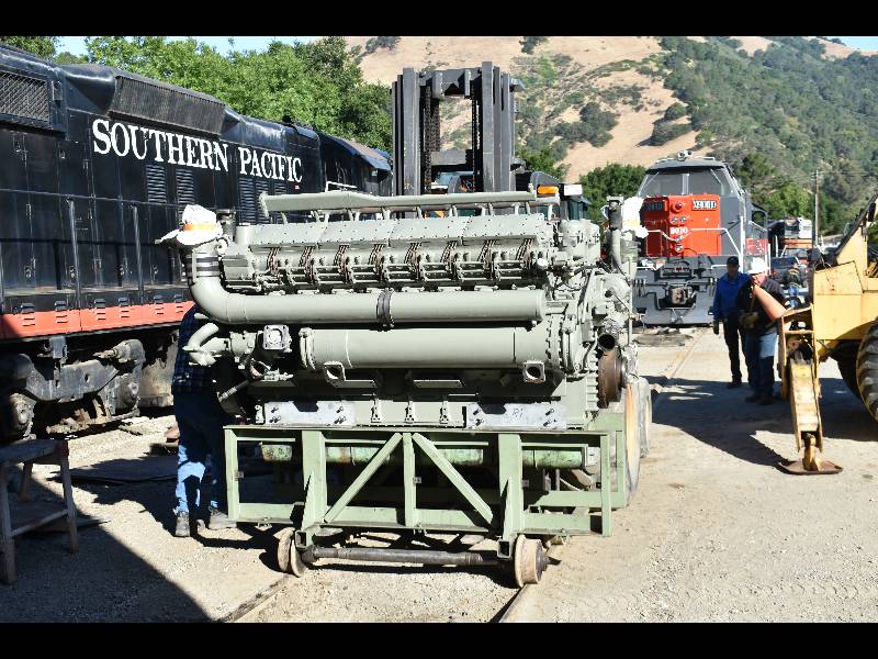
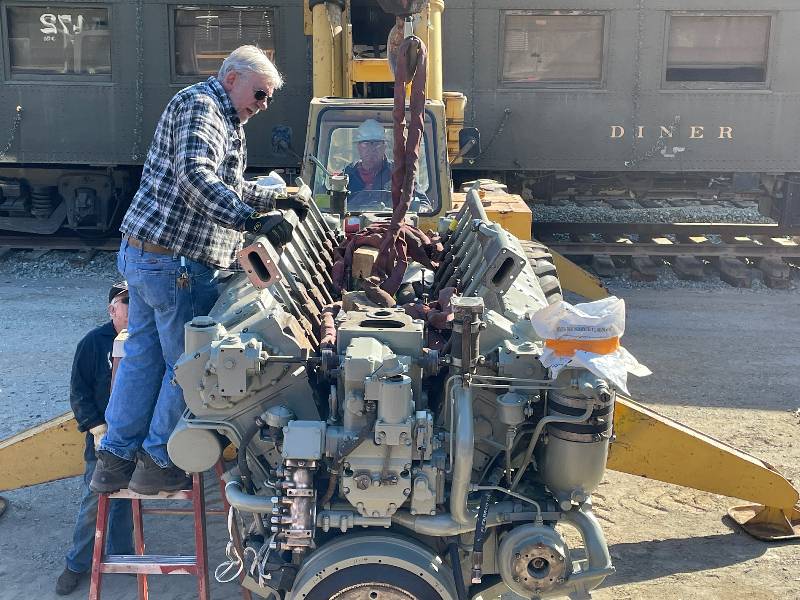
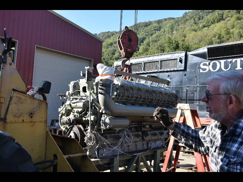
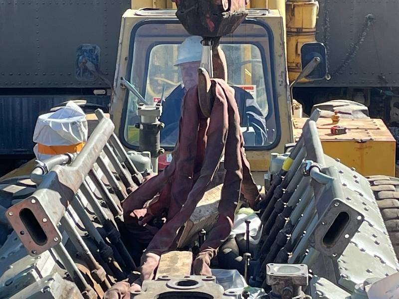
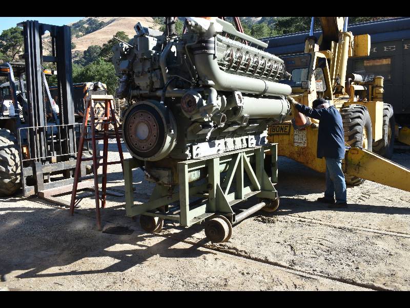
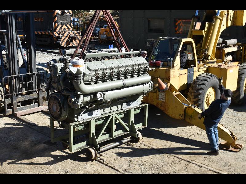
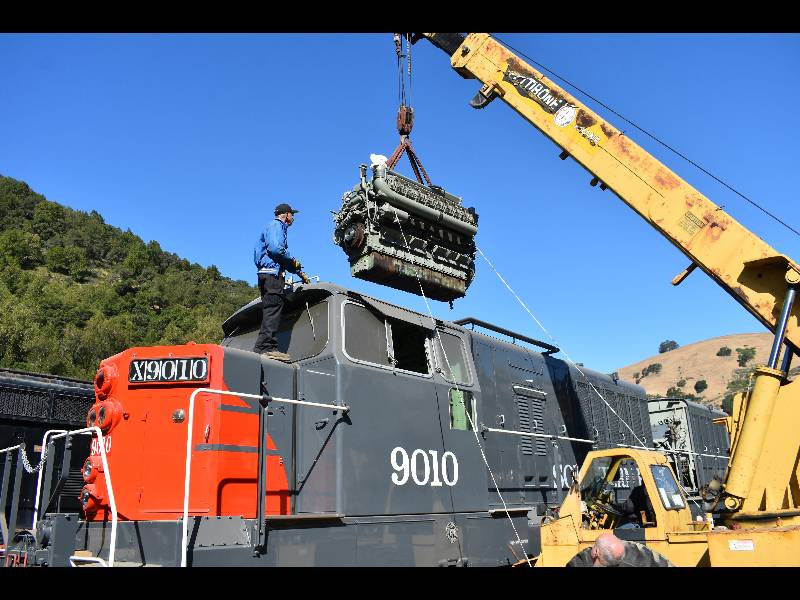
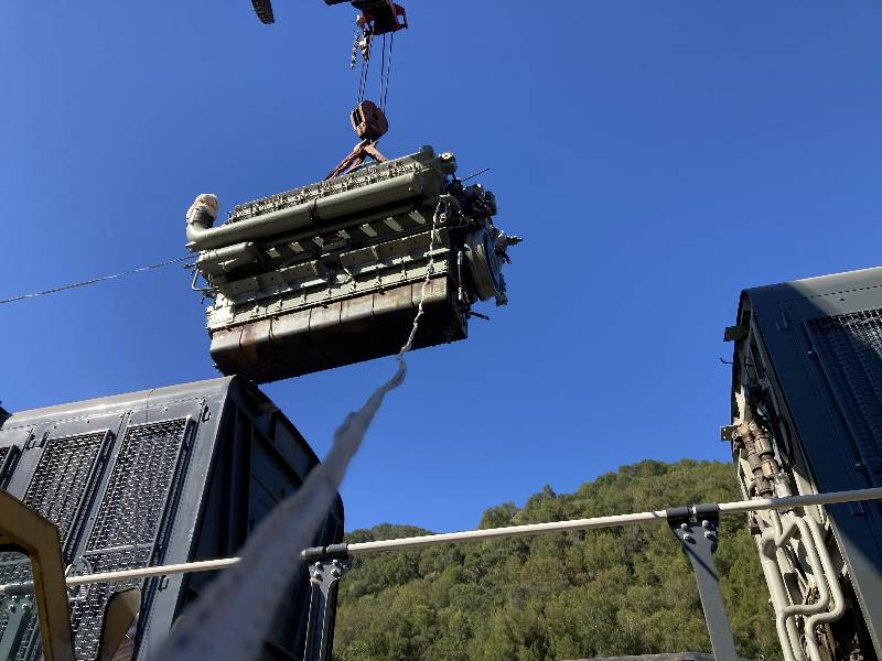
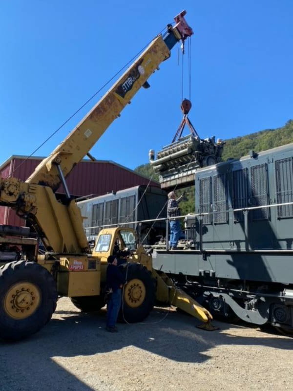
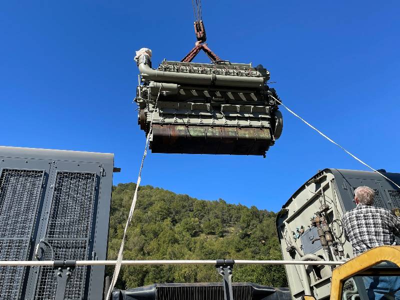
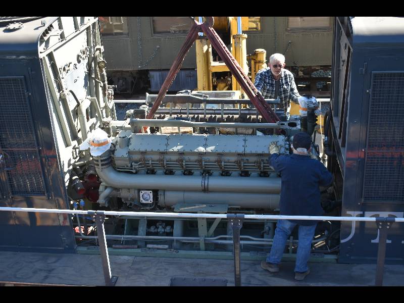
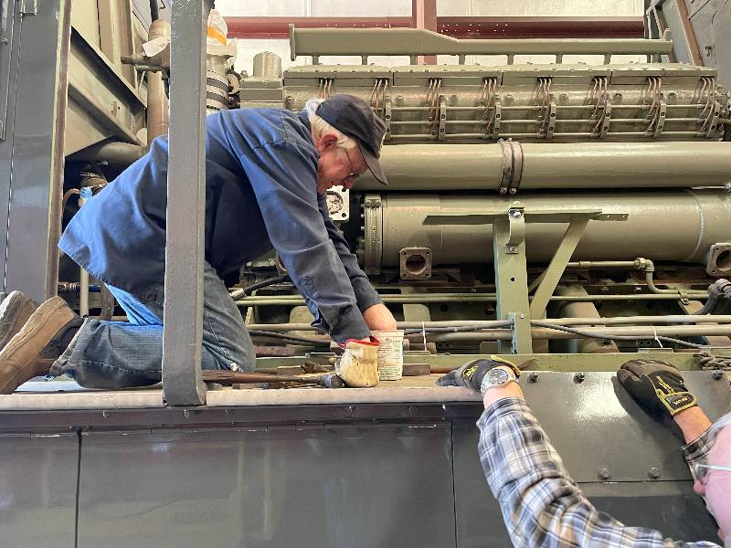
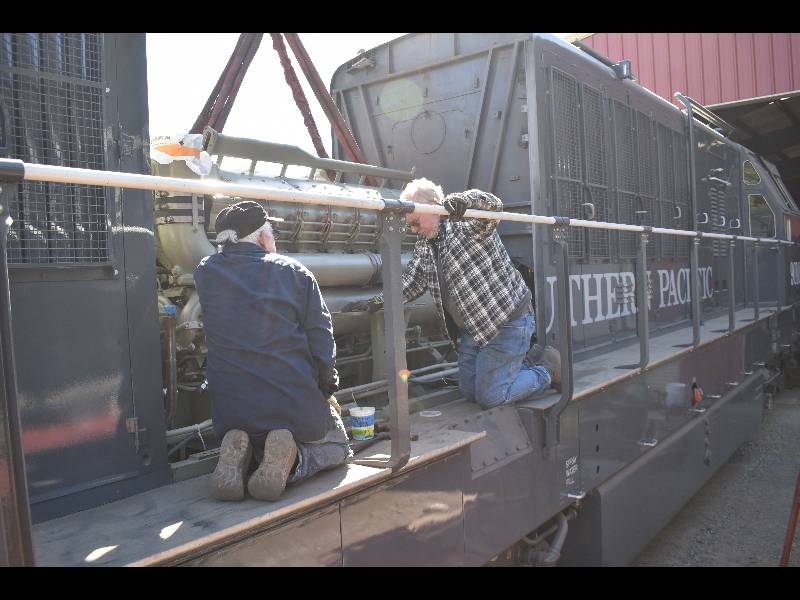
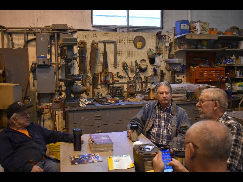
The Maybach is back in the 9010! Yesterday (May 24th), the crew consiting of Steve, Bill, Howard, Karl, Gerry, Rich, Dee and Dennis manuvered the engine back into the tight confies of the 9010's #2 engine bay. Everything went smoothly and by coffee break at 10:30, we were finished. Here is a little photo record of the proceedings.
Return
To Main PageThe Maybach is back in the 9010! Yesterday (May 24th), the crew consiting of Steve, Bill, Howard, Karl, Gerry, Rich, Dee and Dennis manuvered the engine back into the tight confies of the 9010's #2 engine bay. Everything went smoothly and by coffee break at 10:30, we were finished. Here is a little photo record of the proceedings.
 |
 |
 |
 |
 |
 |
 |
 |
 |
 |
 |
 |
 |
 |
 |
 |
 |
 |
 |
 |
 |
 |
 |
 |
 |
 |