|
Southern Pacific
9010
Short Hood Reconstruction Page 2 -- Update July 16, 2009 -- There has not been much visible progress on the nose because so much time is going into getting parts to fit properly. And, other projects around the railroad have taken some of my time. But, this past Tuesday, July 14, Jon and I connected a lifting strap between the nose and our forklift in order to raise the nose and set it on some stands so it would easier for me to work on the lower areas. This gave us a unique opportunity to see the nose from the back as well. I was even able to catch a quick glimpse of the fabled "grinning number board gnome who was checking on our work. In the process of doing the lift, we asked ourselves, "isn't it about time for that final test fit?". The answer, of course was, "Yes"!
With Rich Anderson on the crane controls and Jon in charge of the tag line, the nose was hoisted into place. With assistance from Rich Alexander, our creation sat down on its mount like it was happy to be back. Aside from one easily corrected problem between the nose exterior sheet metal and the front of the cab, the fit was perfect. In the final photo, Rich, Jon and I assume the "proud Papa" pose. It has been 41 years (1968 - 2009) since our Krauss-Maffei has looked anything like this. Now, we have a better vision of the future.
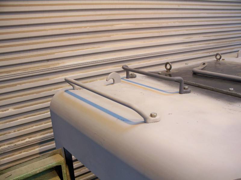
-- Update July 30, 2009 -- Once the final test fit was done, attention turned to all the finishing work. One item that had been neglected until this time is the mount for the recessed white dual gyro light. Because the light housing is wider than the front vertical part of the nose, the mount is a rather complex affair. The following photos will hopefully explain the mount and the process of making it. The rounded area between the mount and the body sheet is 100% welded on the inside and will be smoothed with automotive body filler on the outside.
The front lights require a group of resistors for dimming and voltage control as the locomotive voltage is 72 and the bulb voltage is 32. All the resistors were originally mounted in the nose but I don't know where so I elected to build a panel which contains all the resistors plus the control relays for the red warning light.
-- Update August 16, 2009 -- Welding continues on the lower part of the nose. It is done slowly in order to avoid warping the metal. Generally, a weld pass of no more than one inch (2.5cm) is made and then the metal cooled by the application of a wet rag. All of the vertical joints are now welded and course ground, at least up to eye level. The final finish of the joints will be done with body filler. The next step2 will be to take the nose off of the jack stands so it is lower and then finish all the front welds. As a little escape from the boredom of welding, I prewired the resistor panel and installed it into the nose. Wires will be routed to the panel through the conduit in the locomotive floor that used to contain the wiring to the front transmission.
-- Update August 25, 2009 -- The joints where the front angular sheets meet the top and front center sheets are a particular pain to finish. There are 40, 50 and 90 degree angles plus the curved transition between the top and the front. I had originally considered simply welding the sheets together and then creating the angle with body filler but this would leave the corners somewhat soft and subject to chipping if hit hard enough. So, I decided to create them with weld buildup and grind them to shape. It is a very slow process due to the need to keep the metal cool but once done, the edges should be strong and decent looking. And on the inside of the nose, we now have the support brackets for the yet to be made number boxes. The pipe seen below the brackets will contain light wiring.
-- Update September 10, 2009 -- There has also been progress on the top of the nose. The central panel has been cut to shape and is now welded in place. The edges were held in alignment by these nifty little clamps I got at Harbor Freight, one of my favorite places to shop. The pieces were tack welded every few inches, the clamps were removed and then the weld completed. As mentioned before, there were liberal application of a wet rag to keep the metal cool so it would not warp.
Construction has also started on the "hatch cover" for the top of the nose. The cover allows access to the front Dynastarter which is located on top of the front transmission. Granted that the transmission is missing but, the hood would not be complete without the cover.
Bob Zenk came down from Seattle to spend a few days working on the beast. Knowing of his experience with body fillers, I prevailed on him to work on the finishing touches on the nose. Thank goodness he agreed to do it. Believe me, the guy is an artist. He is also a little warped.
We also fabricated and installed the two little door stops that keep the classification lights from hitting the white gyro light mount.
-- Update September 25, 2009 -- Once I got a good coat of epoxy primer on the center section of the nose, I decided to have some fun and mount the light housings. And, I finally managed to locate 3 rubber bumpers for the door stops and gave them a test run. Then some masking was done so I could paint the interior of the nose Suede Gray in preparation for wiring the lights.
A bit of wire, some cable clamps and a few hours labor led to a test of the lights. A short video of the dual white light is located here. The loose black wires seen in the last photo are for the class lights and number boxes.
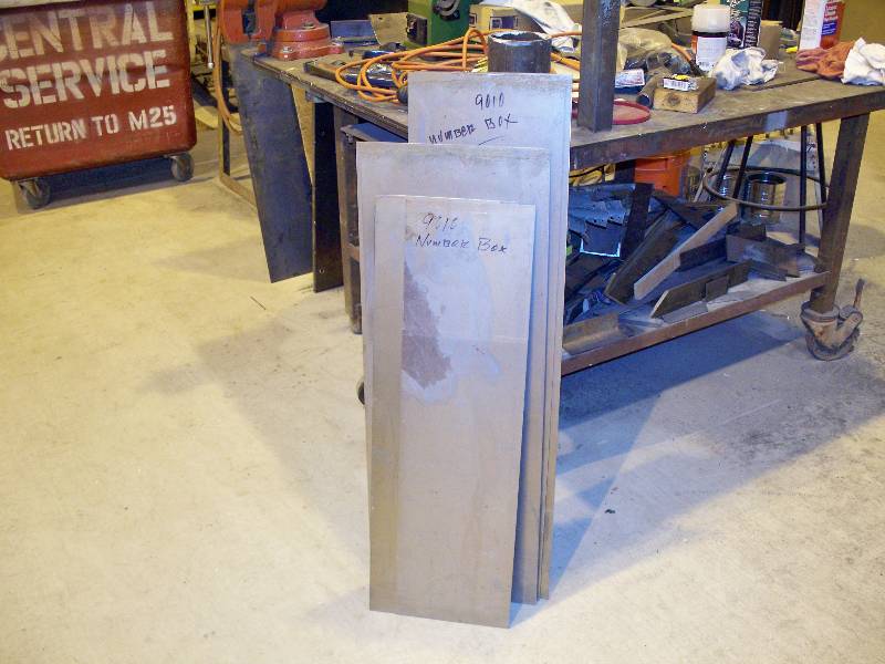
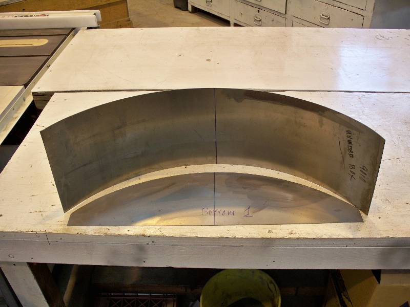
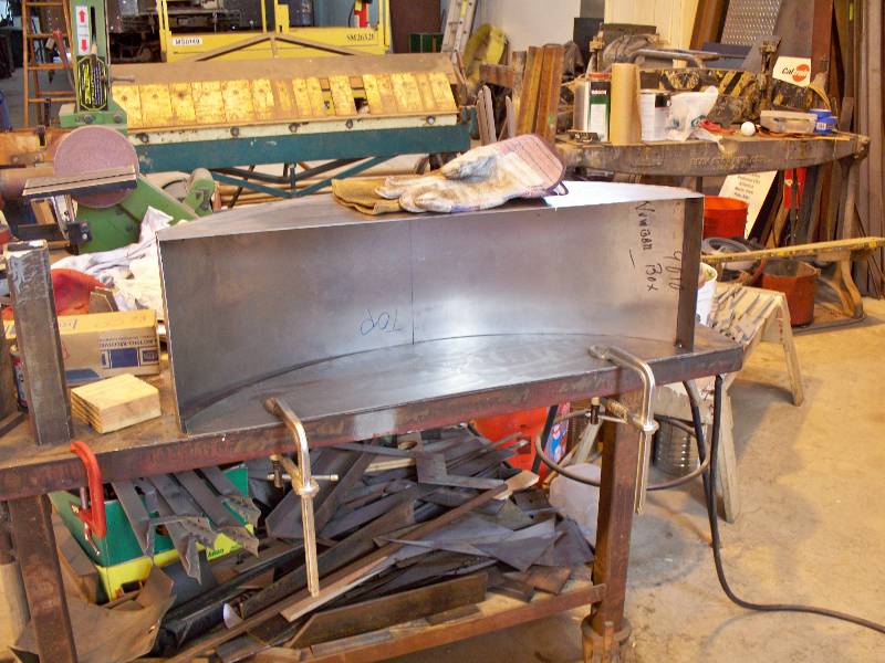
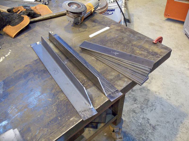
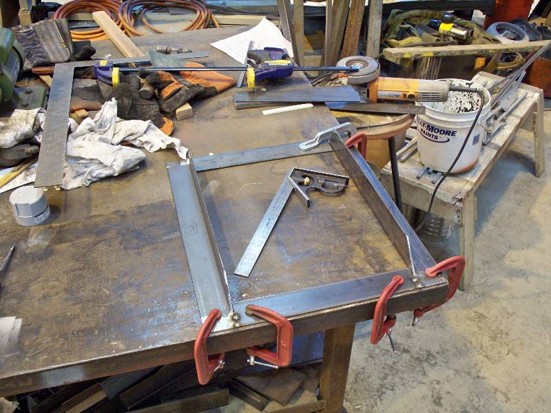
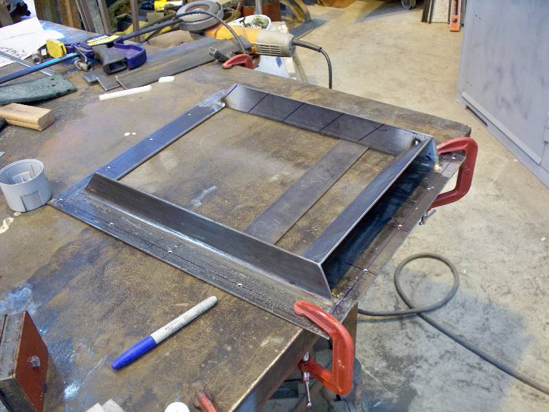
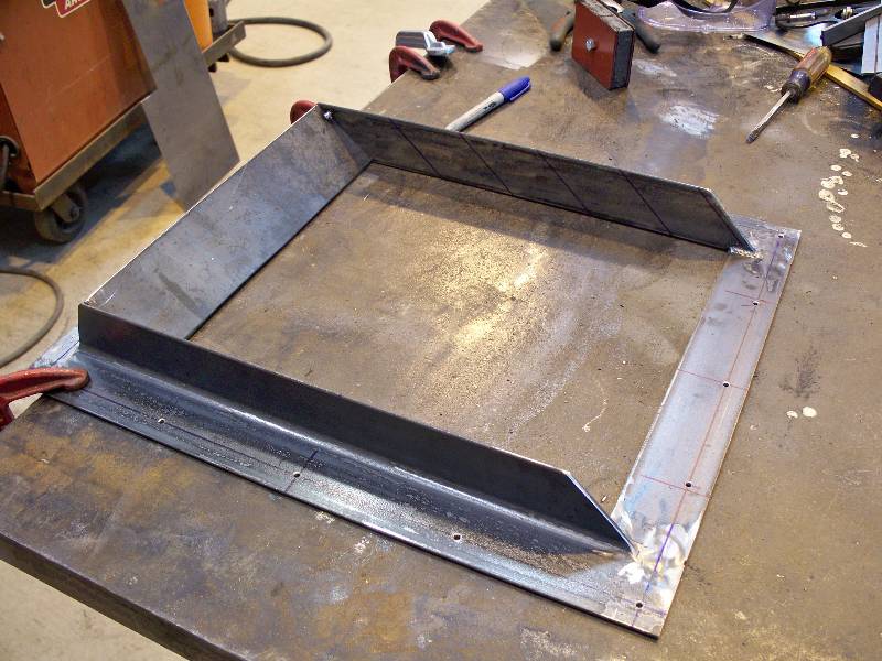
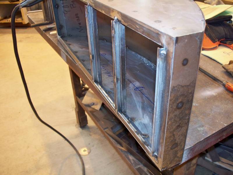
-- Update November 07, 2009 -- The number boxes are the only major construction items yet to do so I decided to start on them. Using dimensions from the number box lent us by Bob Zenk, I had bottoms, tops and backs sheared out of 16 gauge steel. The backs were formed in our sheet metal roll with a little bending on the ends thrown in for good measure. The front frame was made from 1/2" angle iron and was welded to the inside of the box assembly.
And just for the heck of it, we test fit the newly made grab irons on the top of the nose.
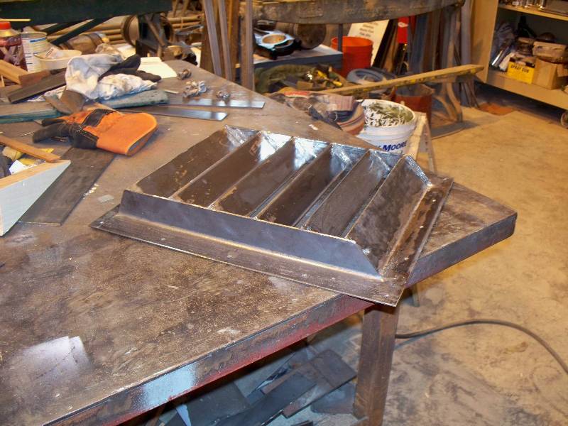
-- Update November 20, 2009 -- I have been wondering for some time how to fabricate the cab heater fresh air intake that is bolted to the top of the nose hatch. After extracting the dimensions from the drawings that our friends in Germany got from Krauss-Maffei, I realized that 2" angle iron would be fine for some parts and 1/8" flat plate would make the rest. A little MIG welding here and there and we have a vent. The next to the last photo is of the bottom and shows the "duct" that will direct water into a drain box.
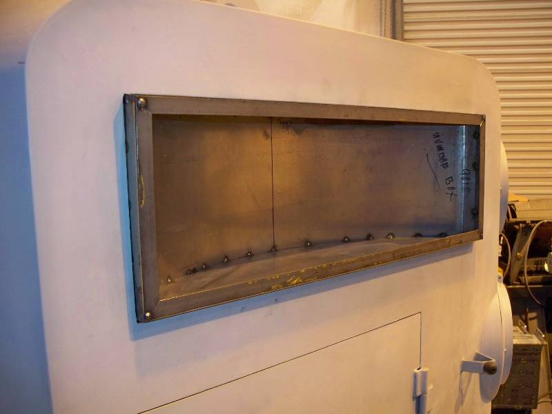
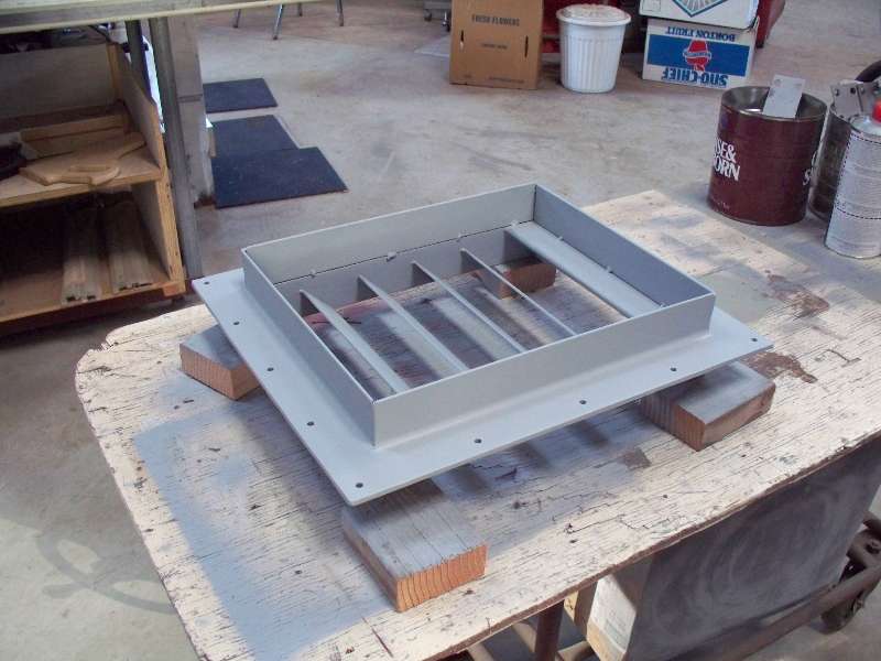
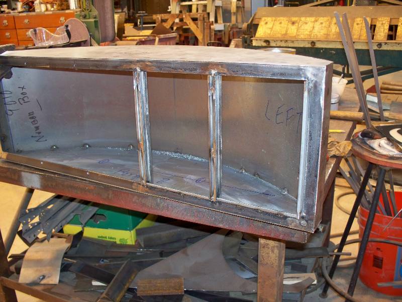
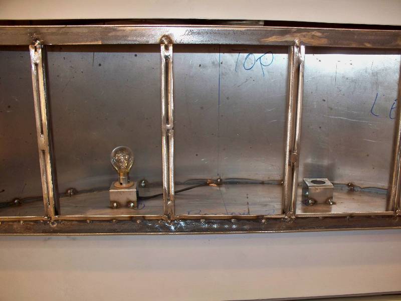
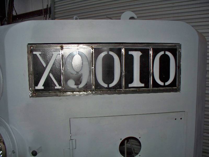
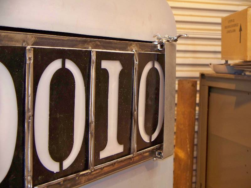
-- Update December 03, 2009 -- After completing the top vent, it was back to the number boxes for a while. The parts that hold the number plates are made of very small angles which were probably custom formed by Krauss-Maffei. We have no way to make anything like this so I set out to find something dimensionally similar. While trolling the hardware store, I became aware that a shelf bracket strip, sawn in half, would probably do nicely. So, I bought a couple pieces, cut them up and made the required angles. The following photos will hopefully explain the construction. The only other items needed were the little lamp mounts which are welded to the bottom of the boxes and a hole in the side for wiring. Mounting the boxes into the nose is yet to come, as is a little minor finishing work. The doors will have to be formed by a local sheet metal company, as soon as I complete the design.
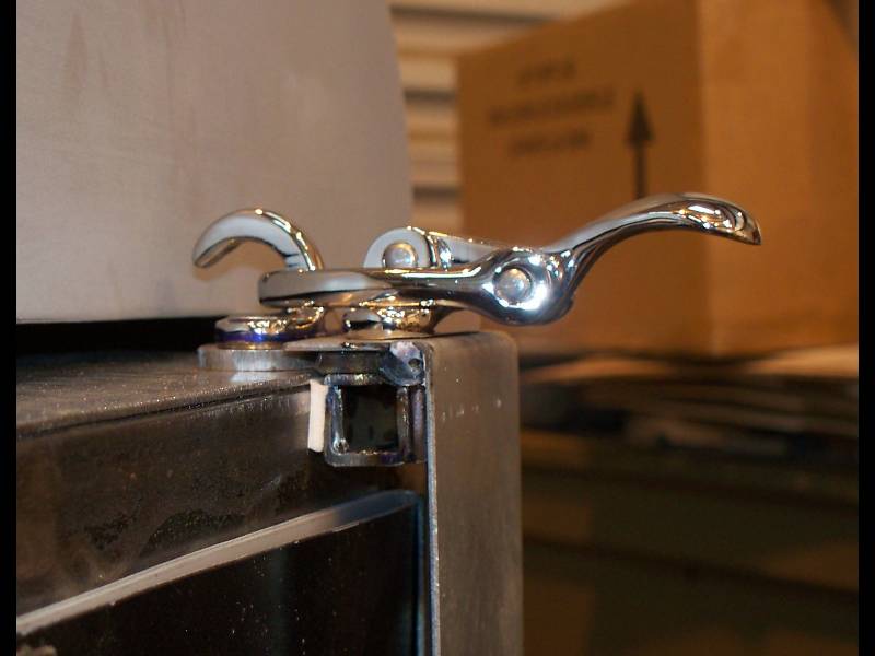
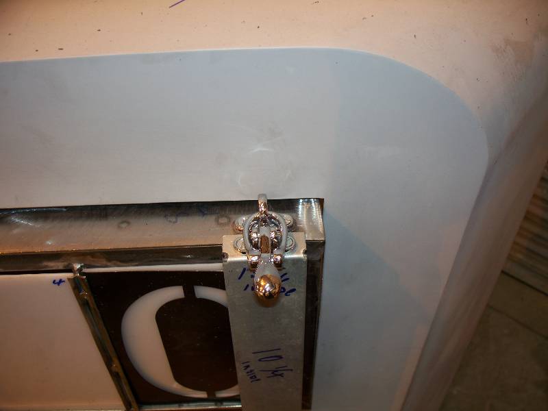
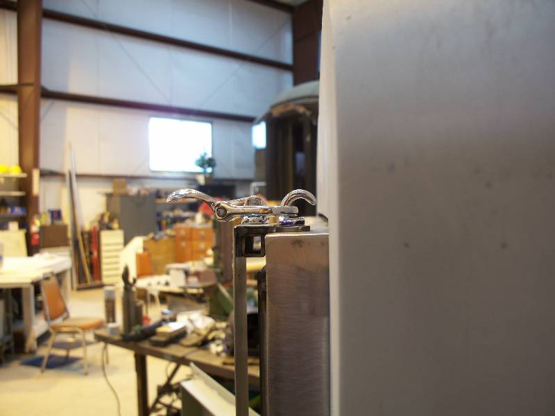
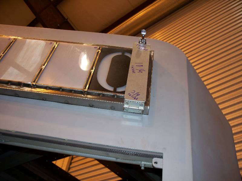
The number boxes doors were a bit of a challenge, primarily because of the latches. The 6 original latches are a complicated design. We think they were made by K-M apprentices and there are no direct replacements. So, for now we chose to use a latch which would look right from the ground and serve the mechanical purpose. The new doors duplicate the old ones to a great extent and should be esthetically pleasing. The first chore in the design was making a mockup of a hinge/latch section of a door.
|