|
Southern Pacific
9010
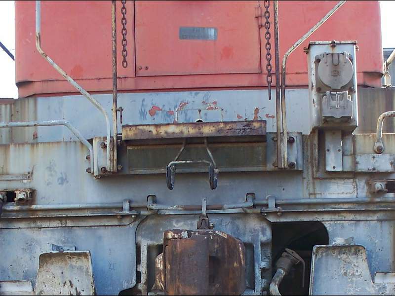
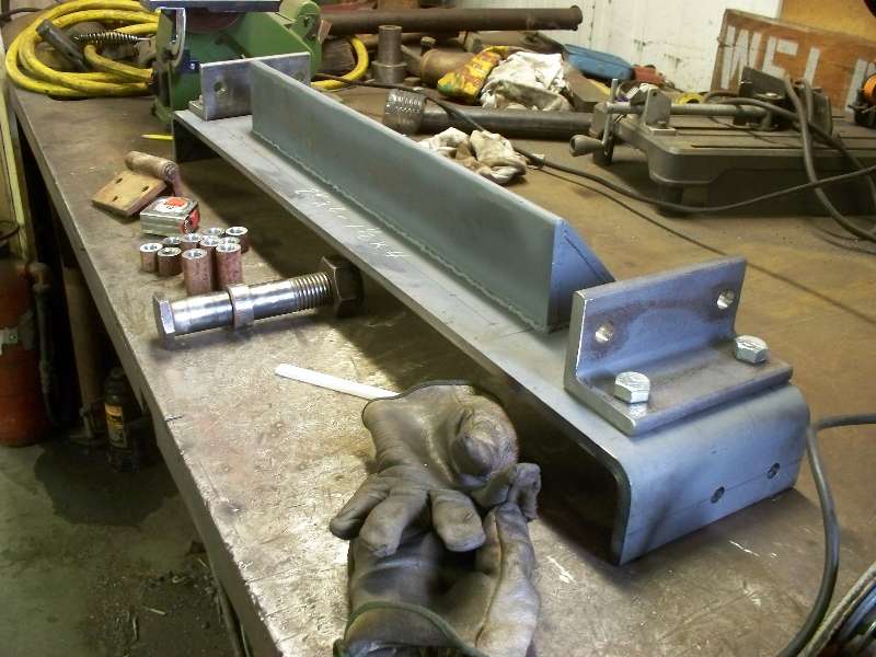
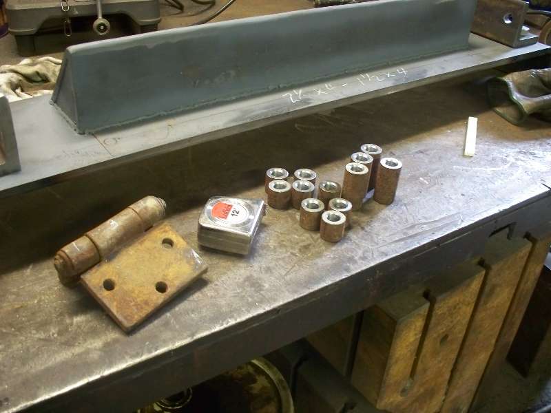
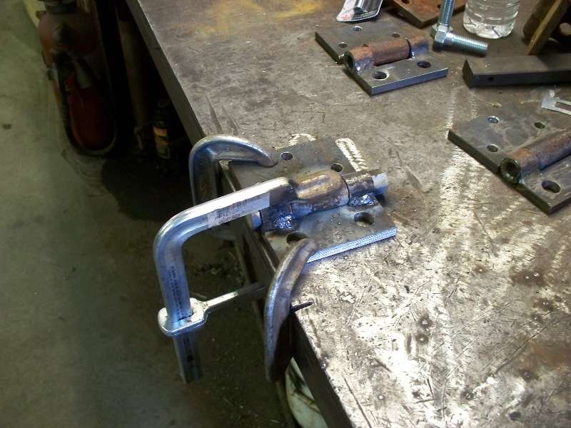
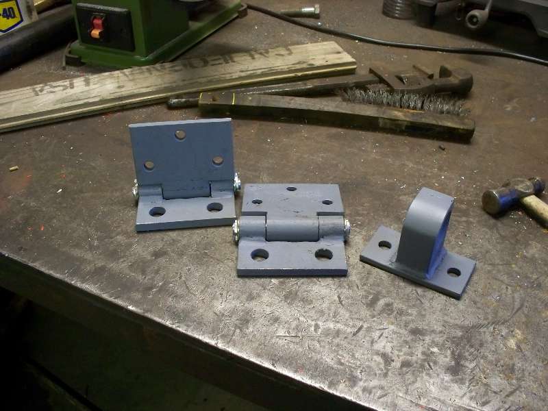
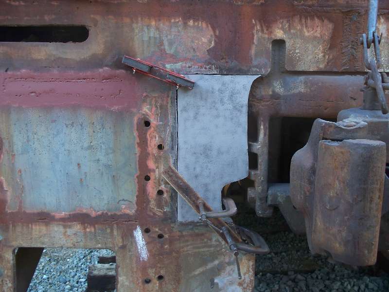
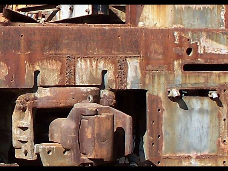
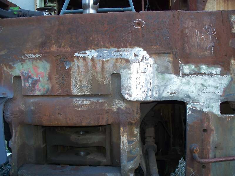
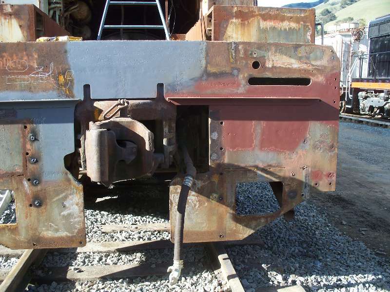
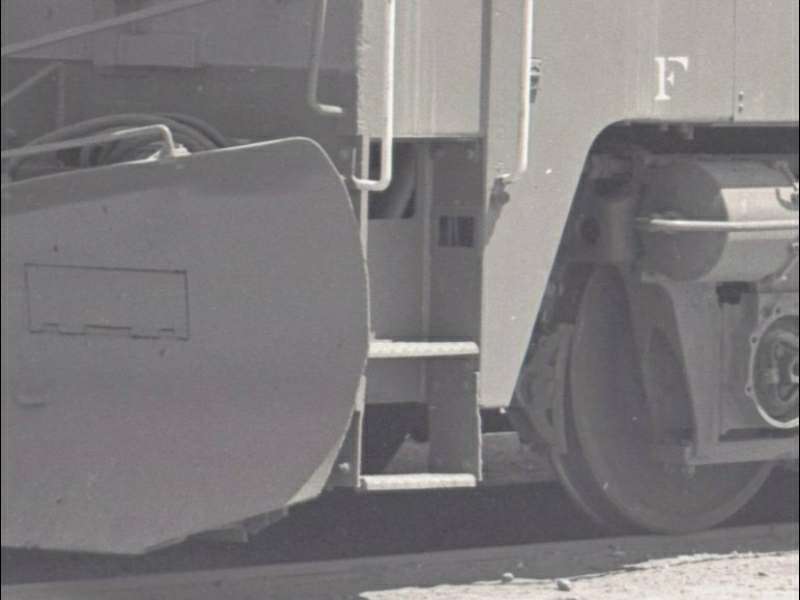
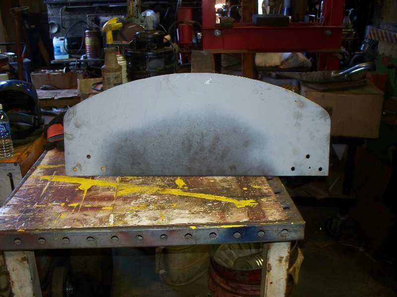
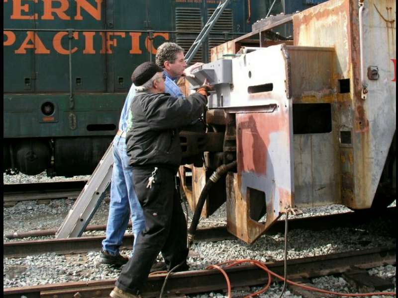
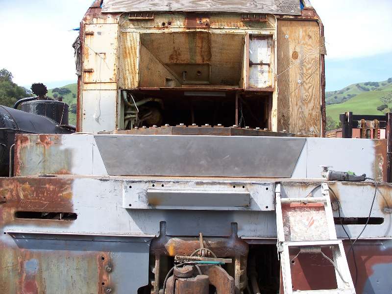
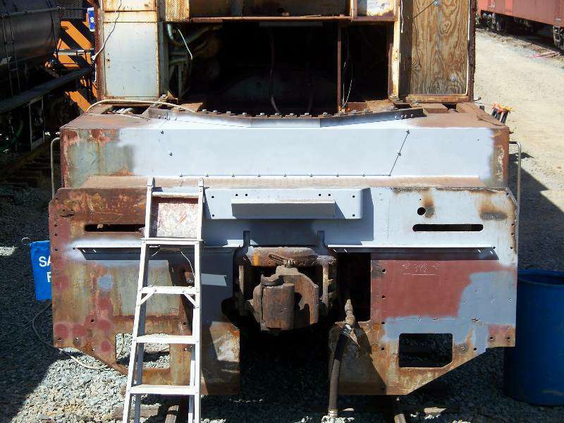
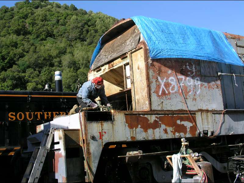
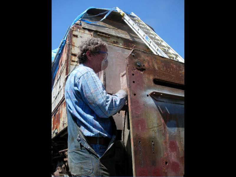
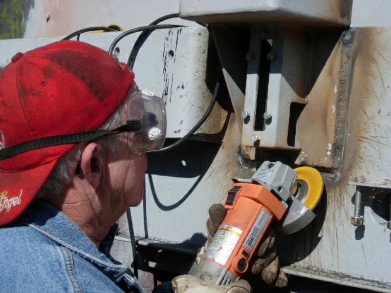
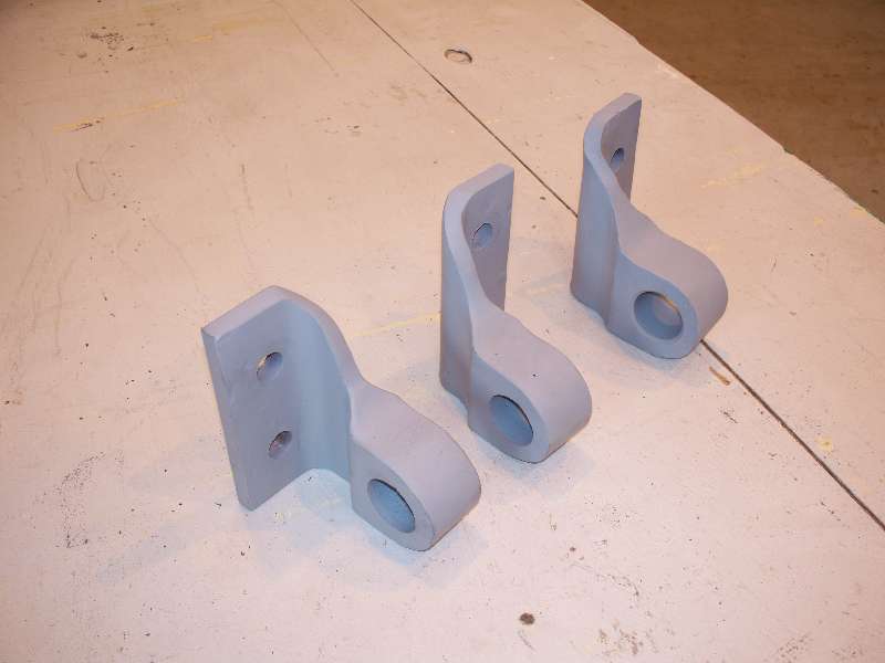
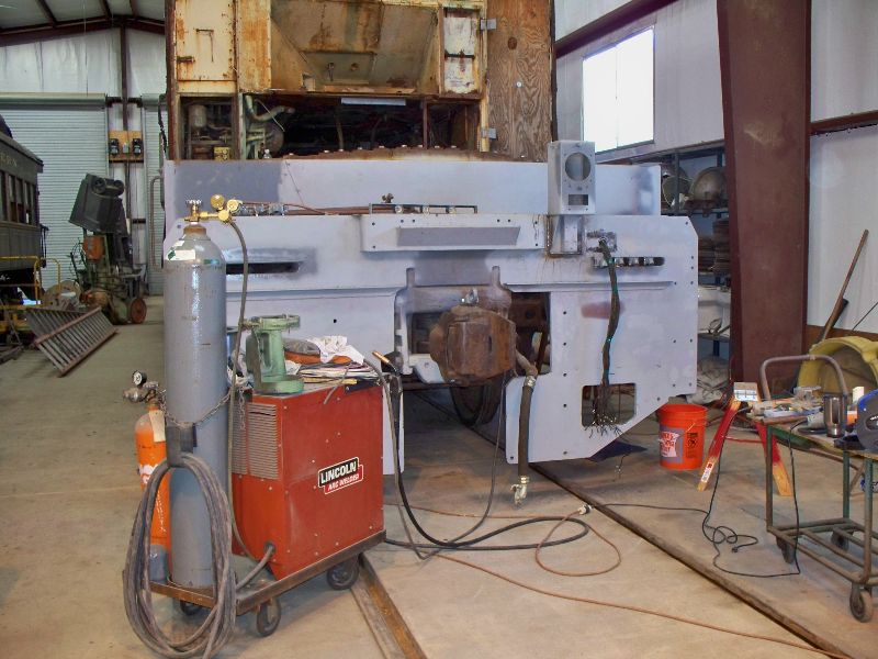
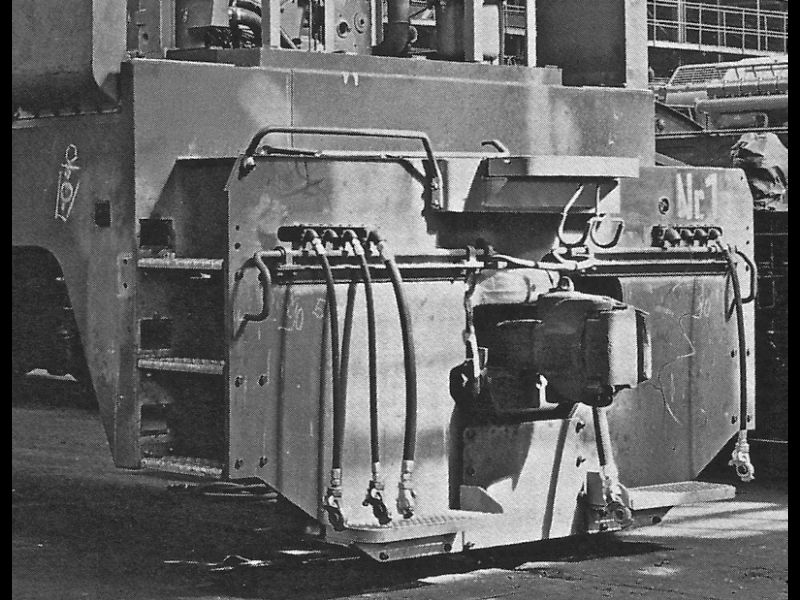
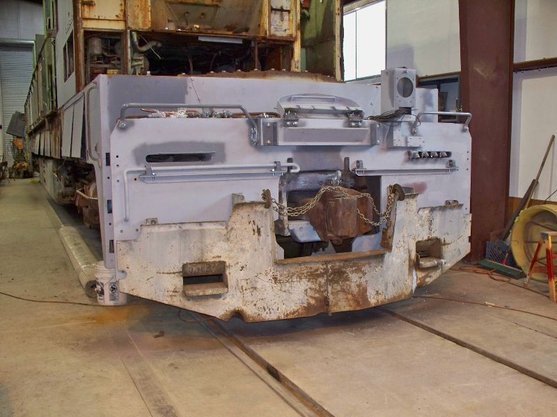
Front End Work Page 1 The front end of the 9010 is a mess. The aborted restoration in the early 1990's at CSRM left it stripped of all the metal applied when the camera car conversion took place. There are extra holes that were used to mount the SP plow pilot and extra slots where the MU pipes were relocated. In addition, there is a large hunk of pilot sheet missing next to the coupler on the right side. In order to make the end look good and somewhat original, all the extra holes have to be plugged, a number of new mounting brackets and plates need to be fabricated and the missing metal needs to be replaced. Fortunately, the rear end is in good shape so we have patterns for all the front end's missing pieces. There is a long, formed plate welded to the center of the end which is used to attach the handrail supports and the MU step. A new one was bent using the time honored manual approach. Brackets for the handrail supports were cut and new MU platform hinges were hand made. We had to make 4 new hinges because the rear ones were damaged. We will also make 2 new platforms as the front one is gone and the rear was in very poor shape. The little block in the forth photo is one of 4 we made that support the cut levers, 2 per lever.
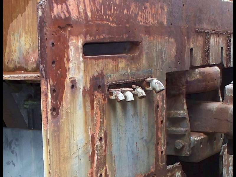
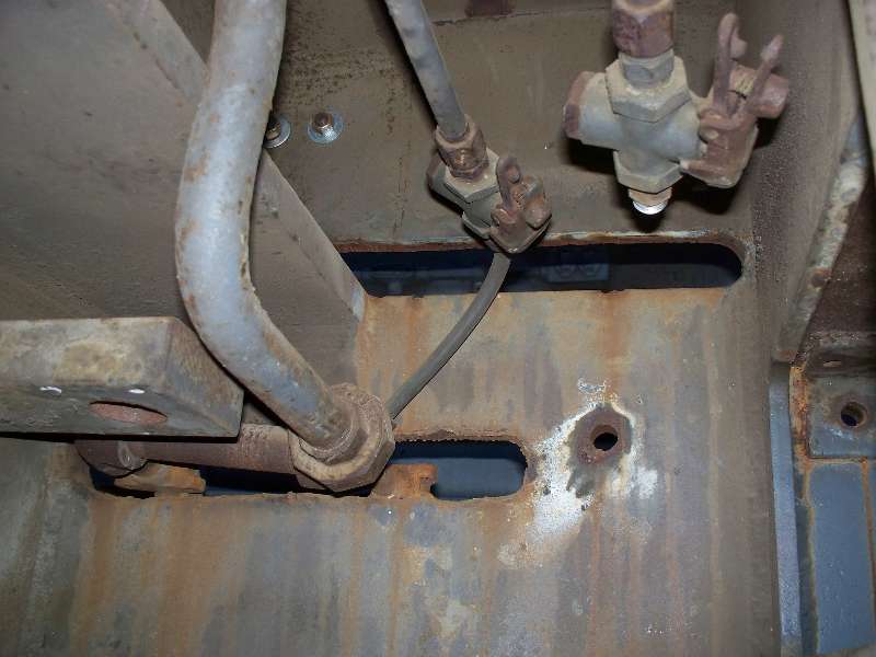
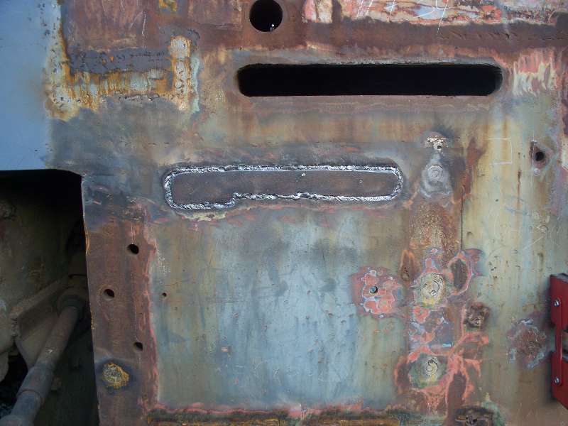
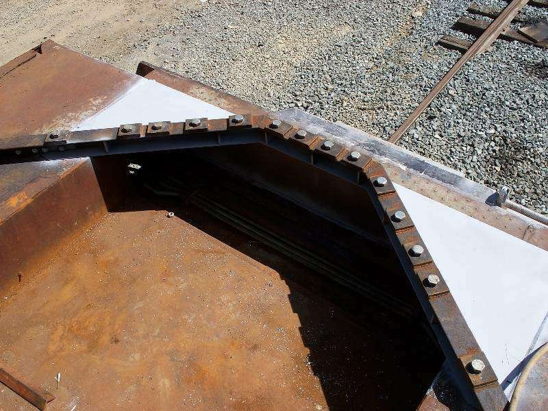
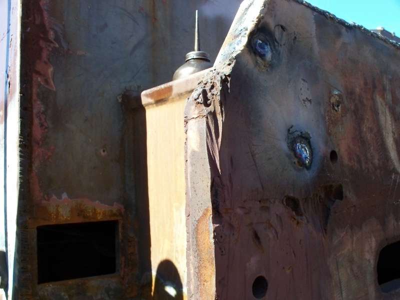
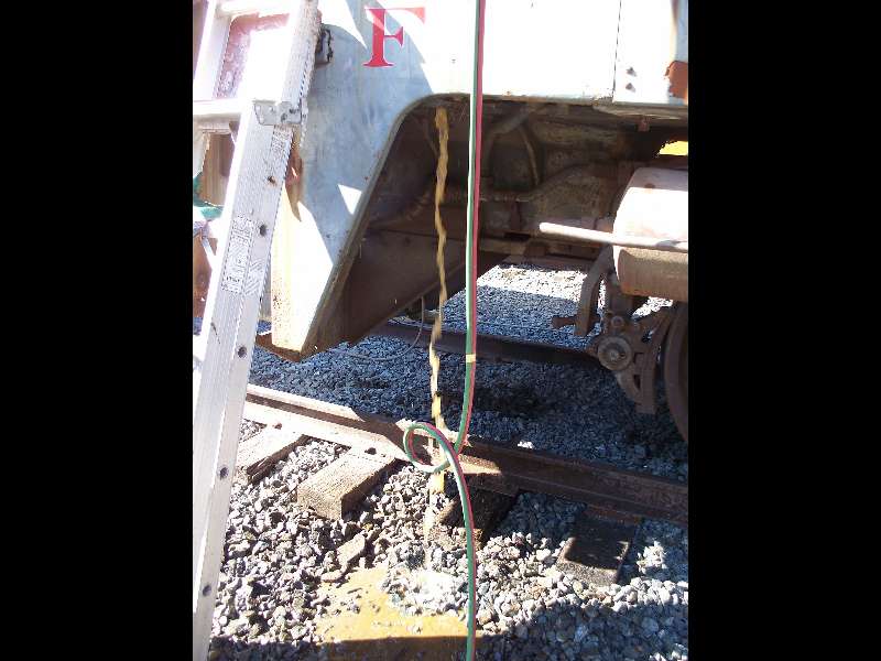
The SP cut 2 slots in the end sheet through which the MU hose fitting elbows protrude. I am not sure why they lowered the slots but it had something to do with the metal work for the camera car nose. The slots needed to be plugged so patterns were made which were used to cut out pieces of 3/4" steel plate which was then welded into the slots. The cut lever seen in the third photo is a temporary one which was applied in order to bring the 9010 down from Sacramento on the U.P.
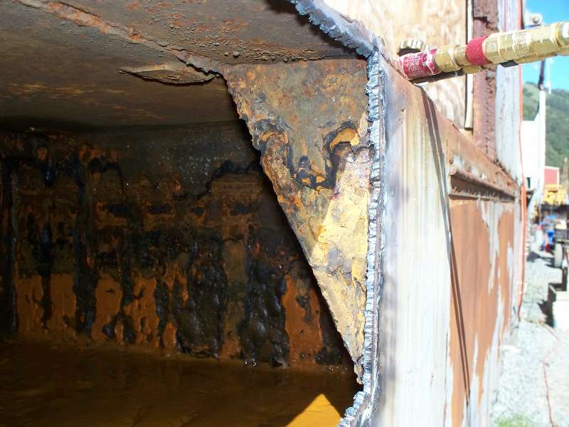
In addition to the MU hose slots, a large chunk of the front sheet had been removed by someone on the SP with a rather limited knowledge of the use of a cutting torch. Does that sound critical? Yeah, I guess it does. But I mean it in a loving and caring way. Another piece of plate was cut, fitted to the opening and welded in place. Finally, the cut lever mounting angle iron was welded into place. The final photo shows our blacksmith Joe Mann test fitting one of the new cut levers he made for the front end.
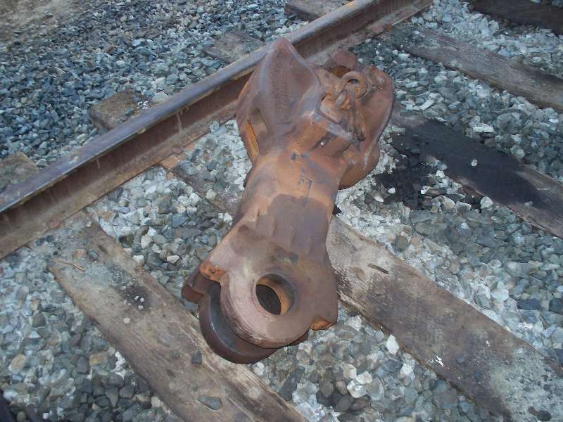
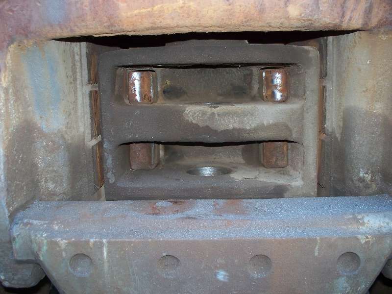
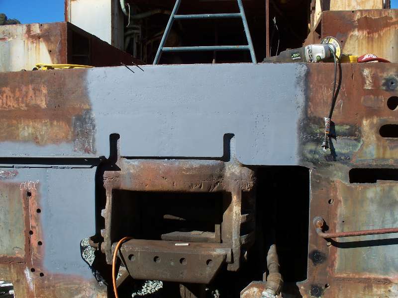
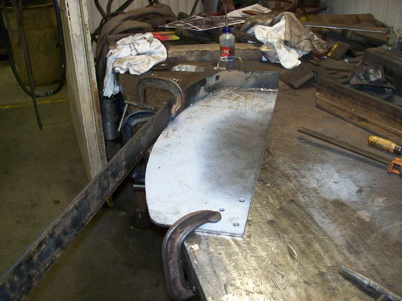
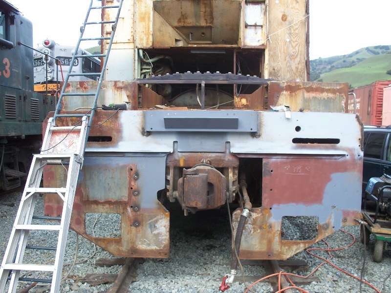
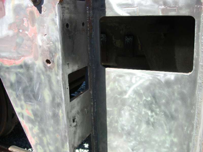
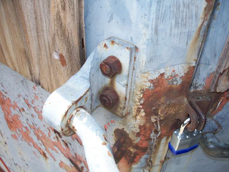
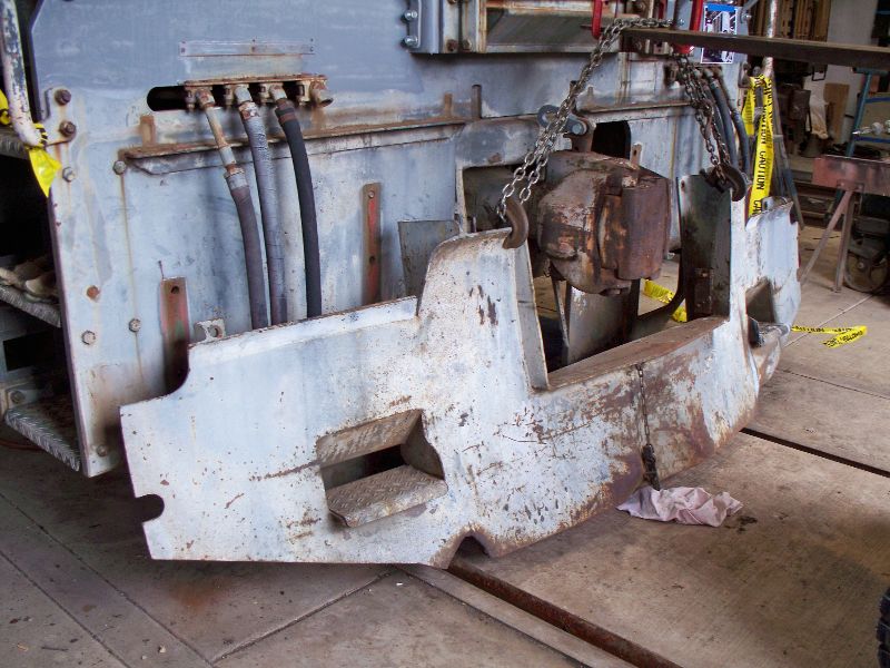
In order to more easily get at the area above the coupler, I decided to remove it. Much to my surprise, it turns out that it is of the "alignment control" type. Note the 4 ears on the shank end and the 4 square posts inside the pocket. The posts bear against springs which hold the coupler centered in the pocket.
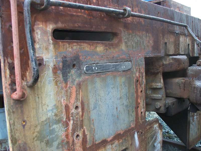
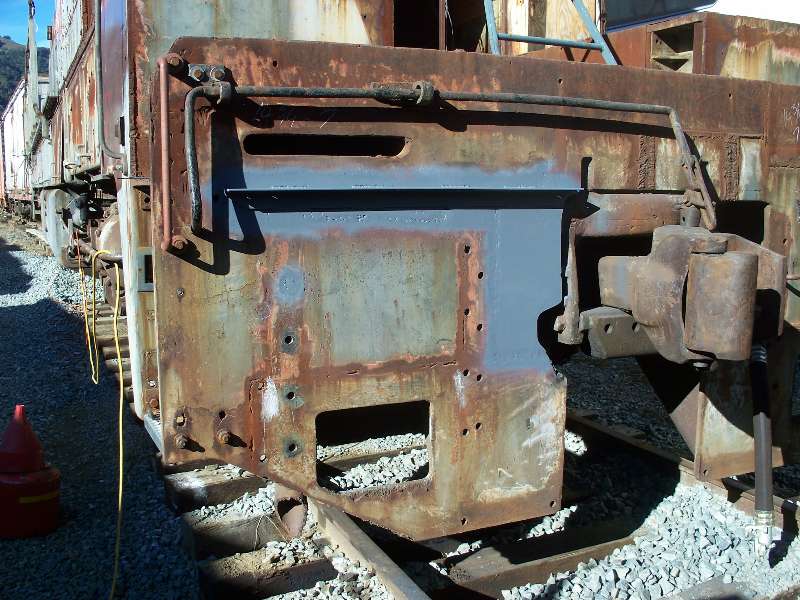
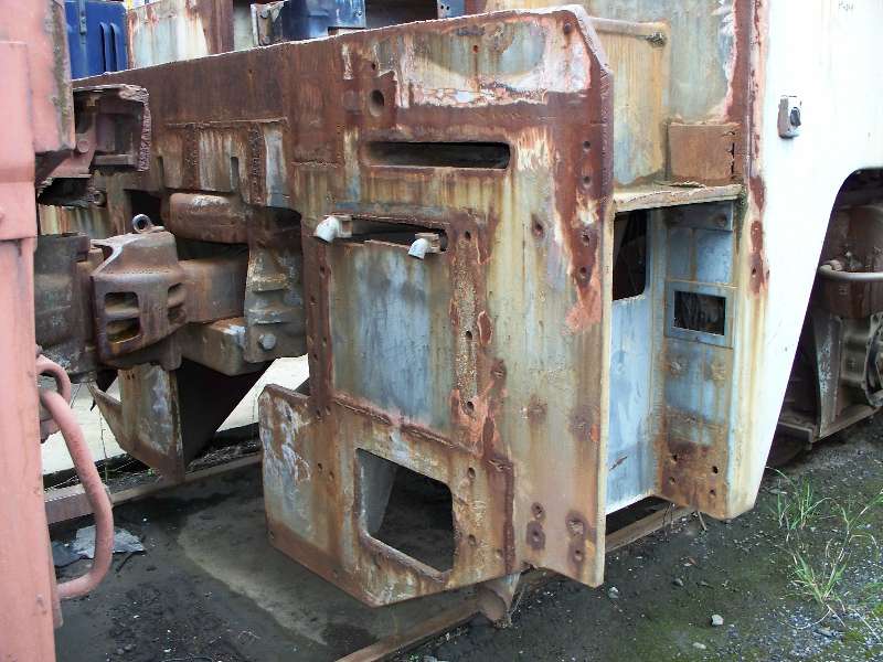
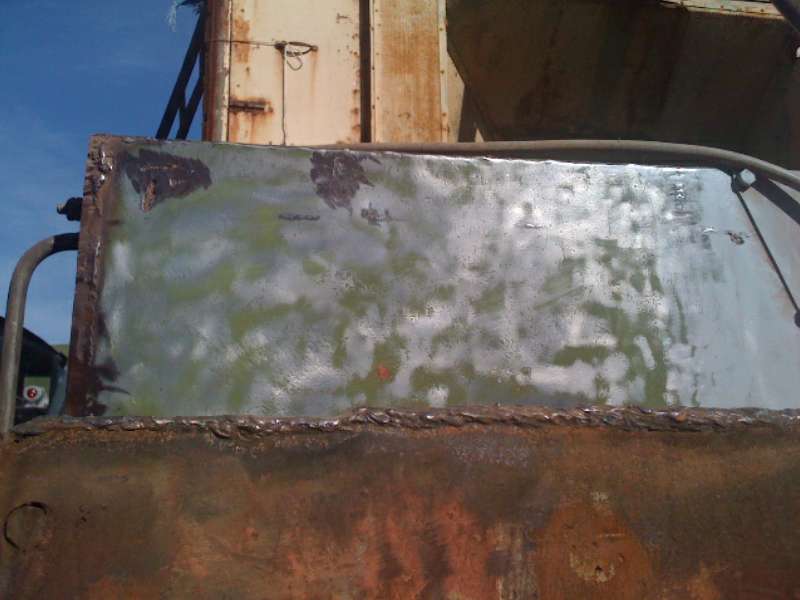
During the camera car conversion, the SP welded a large frame on the end sheet directly above the coupler. CSRM torched it off 20-odd years ago and a large amount of grinding and filler weld was required to make the sheet reasonably flat again.
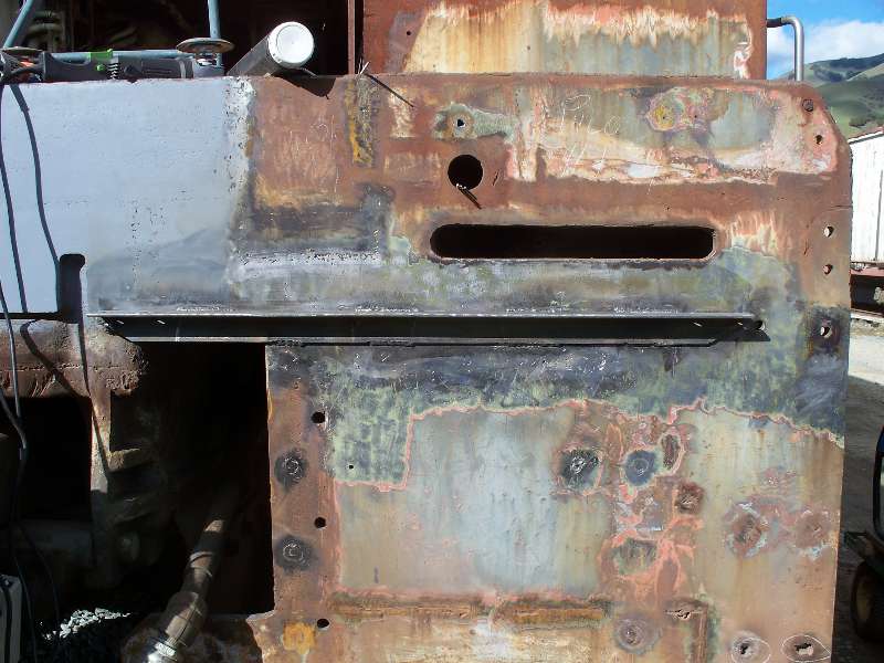
Below is a sequence of photos illustrating the process of filling the remaining lowered MU slot and mounting the cut lever support angle iron.
SP also modified the front corner steps. The top step area was blanked off and extension plates were added to the bottom of the opening thus creating a new, lower location for the bottom step. The old bottom step was raised about 4 inches. Fortunately, the 4 remaining steps on the front end were original K-M steps and will be used in the reconstruction, leaving only 2 to be reproduced.
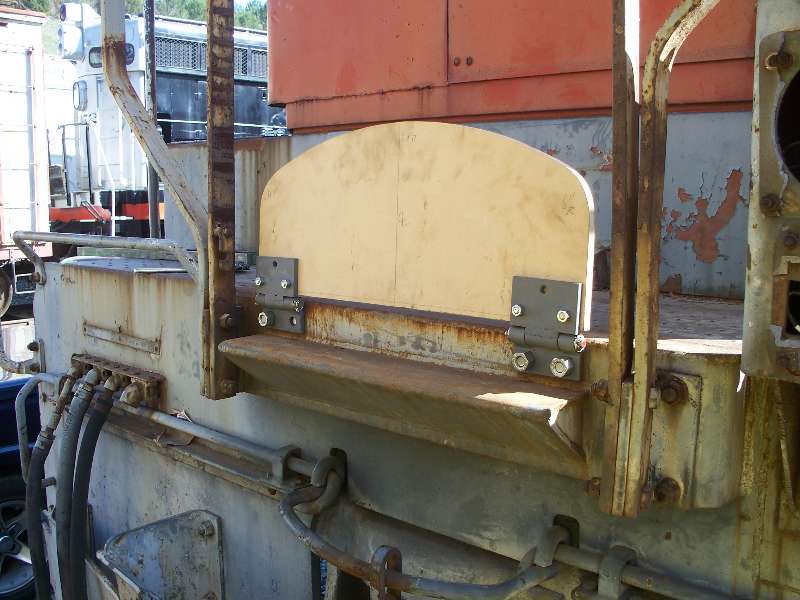
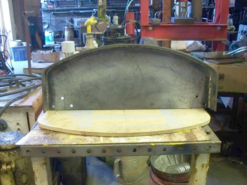
In order to take a little break from the front sheet work, I decided to work on the missing MU platforms. Illustrated below is a wooden mock up of the platform, made to explore dimensions which are only available by scaling from photos. It turns out that the model I made is about 1" too deep and will be cut down before using this as a pattern for cutting the 1/4" steel plate. The platform is made from a 1/4" steel top and a 2 1/2" rim, bent around and welded to the plate. On top will be attached aluminum 2-bar anti-skid tread plate, duplicating the existing decking.
After bending the flat around the 1/4" plate and welding the two together, Rich cut a piece of angle iron that was welded across the underside both to strengthen the assembly and to provide a stop for the platform when it is hinged down into position. The MU cable holder was formed from 1/2" bar stock and welded in place. Aside from sand blasting and painting, the two new platforms are now complete.
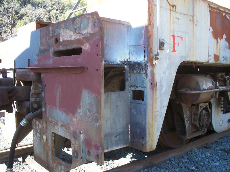
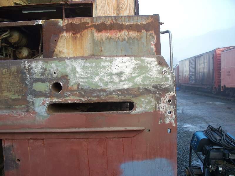
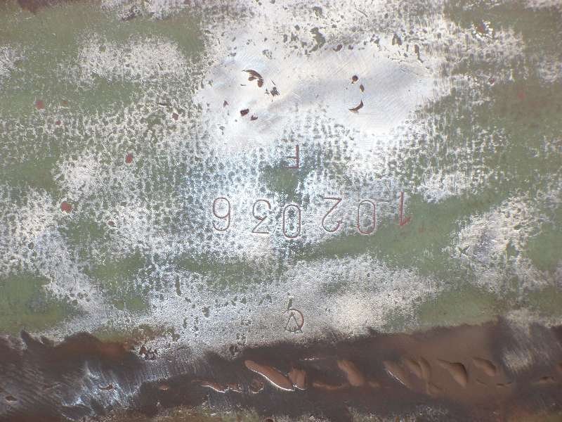
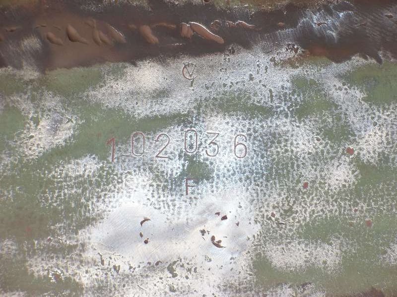
While continuing the cleaning and welding repairs to the front sheet, I discovered some numbers stamped upside down into the upper left corner of the sheet. In photo 3, the markings are turned right side up for your viewing pleasure. From our friends Gerold in Austria and Richard in Germany comes the following information: The "O" is the German Umlaut "O" with two dots/ dashes on top) and a "V" above the number - this is the emblem for the VOEST, Vereinigte Österreichische Eisen und Stahlwerke / United Austrian Iron and Steel Works ; they are located in Linz, about 200 miles from Munich. KM imported its steel from Voest at that time (and Voest bought its locomotives from KM). The numbers most likely represent the manufacturing / lot number. The "F" is probably the QA mark after checking the plate.
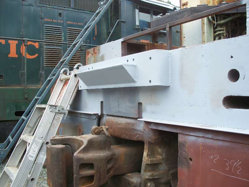
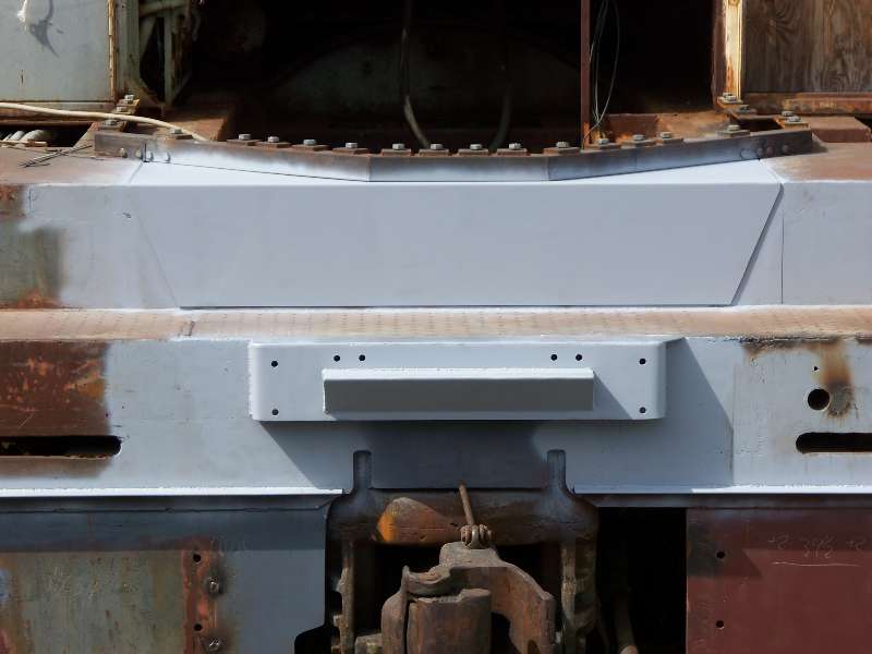
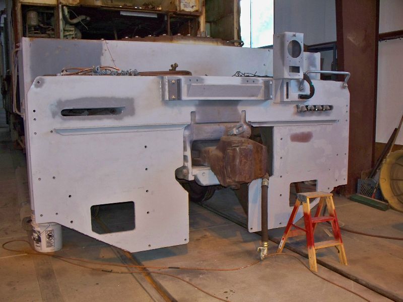
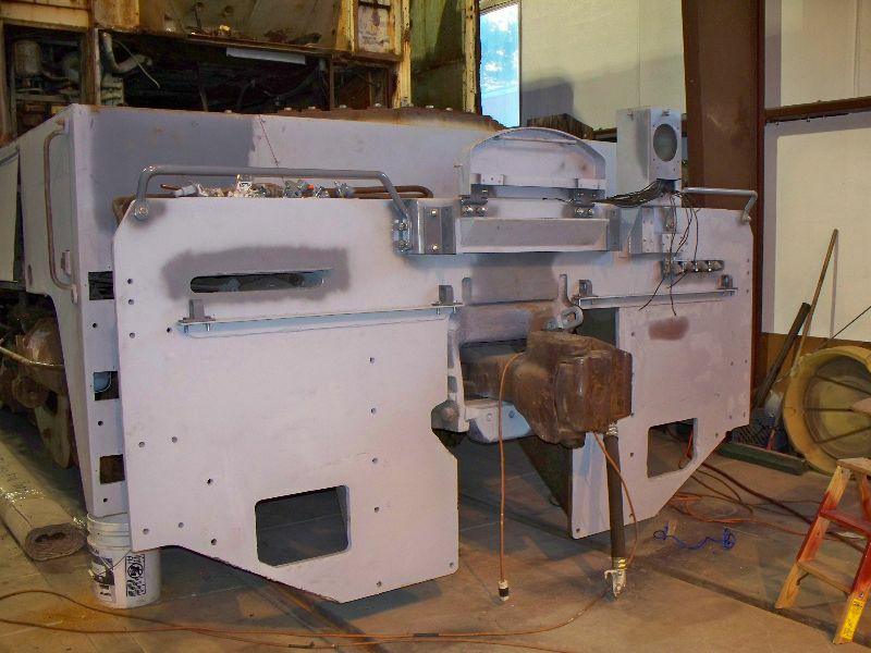
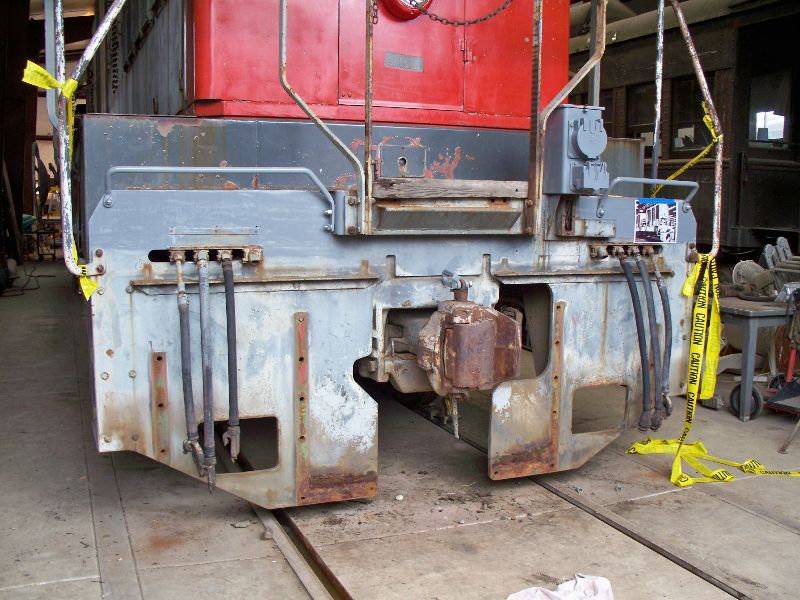
With the cleanup of the front end coming along nicely, it was finally time to weld on another newly-fabricated piece. The gadget directly above the coupler is the MU platform mount and also serves as the attachment point for the front handrails and grab irons.
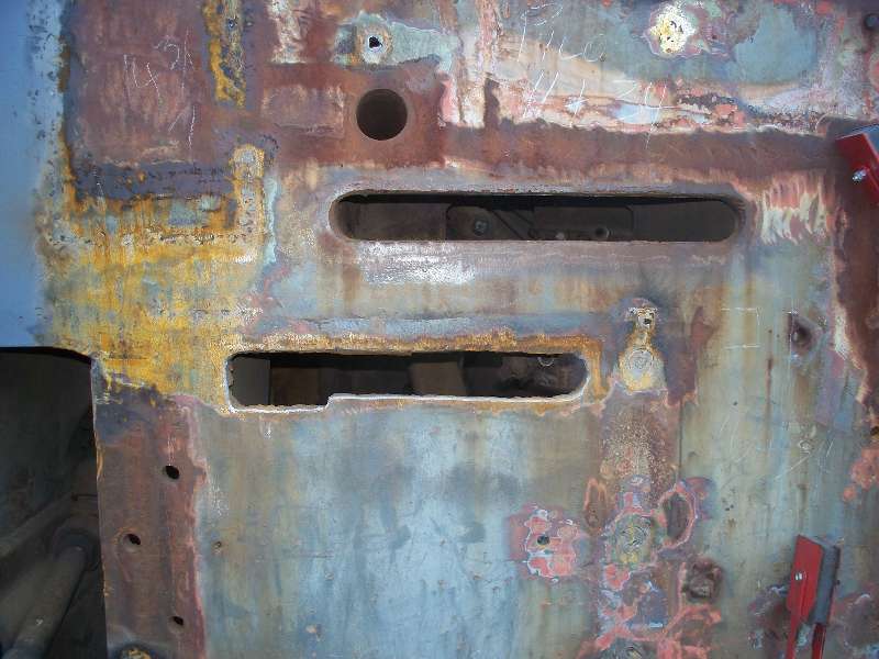
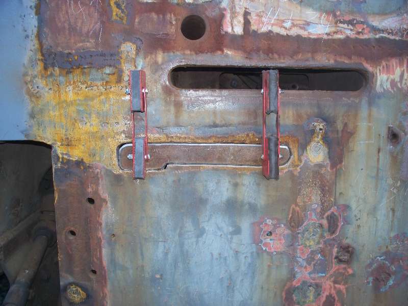
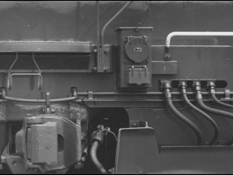
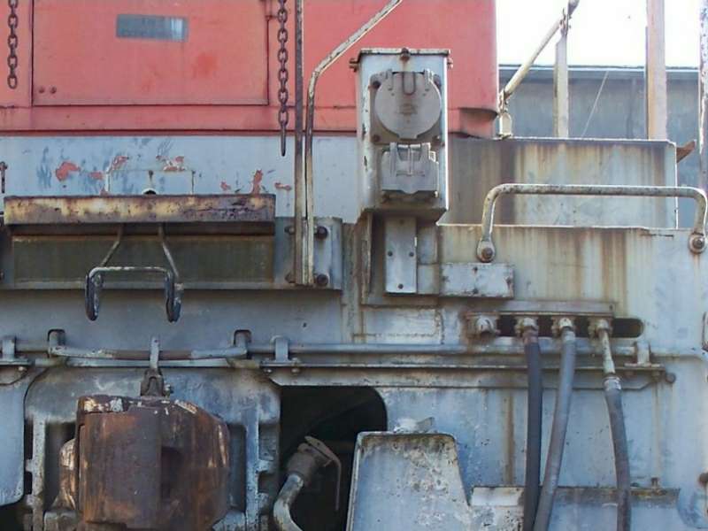
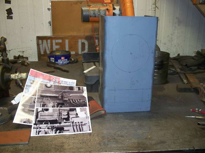
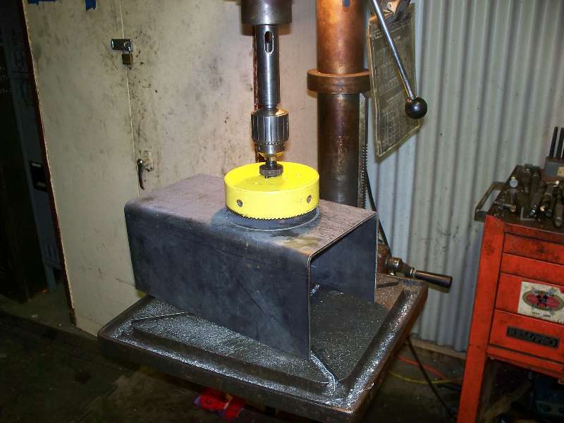
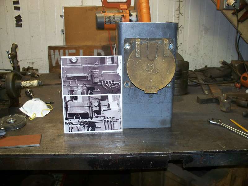
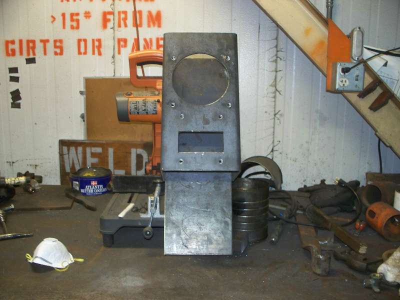
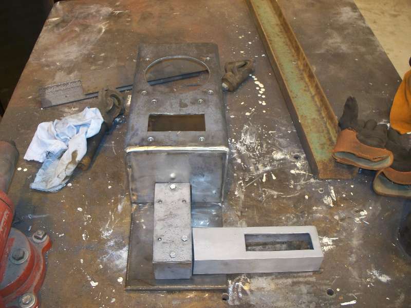
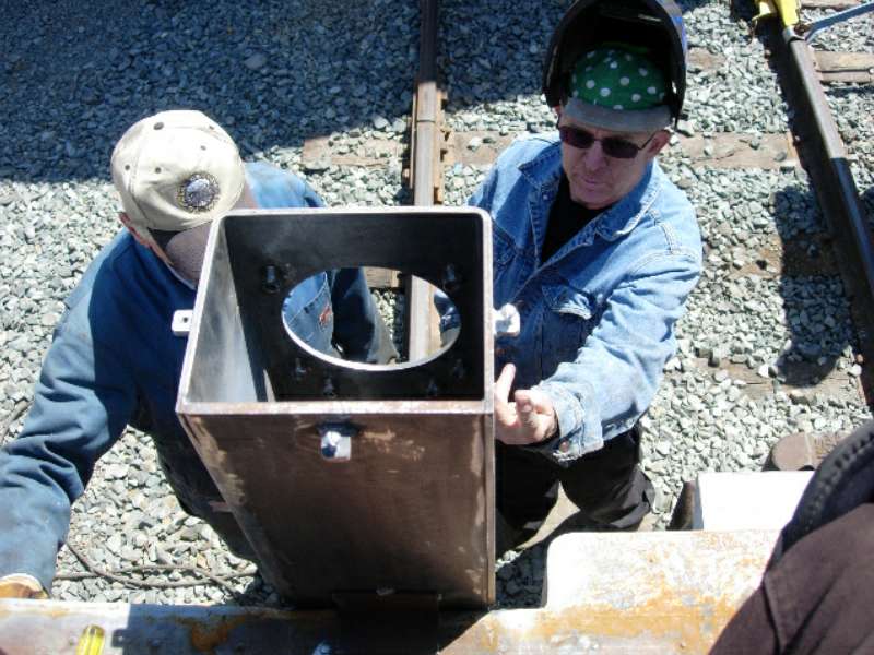
Next on the old fabrication to-do list is the front MU box. Elsewhere in these pages, we describe the ups and downs (actually downs and ups) of the MU box placement. Suffice it to say there that we decided to put the MU box in the position as modified by the Southern Pacific. This means that the front box will match the rear one and we can preserve one of the first modifications made by the S.P. The photo on the left is the original location and on the right is the modified location.
The large hole is for the 27 pin MU socket and the smaller one below it is for the 3 pin dynamic brake field loop socket.
Next came fabrication of the metal ducts that contain the MU wiring. This would have been much simpler with the MU box in the lowered position. And finally Rich and I formed a lid and welded everything that can be finished together. Short of a coat of primer, the box is ready to be installed.
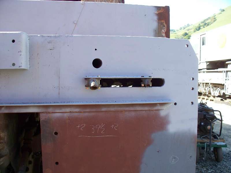
-- Update March 19, 2009 -- The cover over the lower front end was purchased with some fabricated nose parts and became the next project. Rich and I spent the day measuring and cutting the pre-bent sheet of 11 gauge. The next work day, Jon and I took care of the 10mm bolts which secure the plate to the frame.
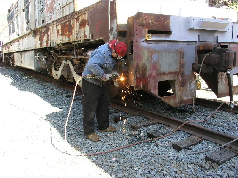
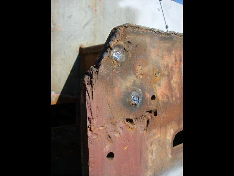
-- Update April 04, 2009 -- One of the cosmetic problems on the front end was caused during the removal of the camera car nose. Evidently, the crew removing the nose used an air arc and made something of a mess of the front frame. Photo 1 is a good example of this damage. The only way to correct this is by building up the area with weld and grinding it down to contour. I spent about 4 hours today doing just that and managed to finish the edges on the fireman's side. Once this was out of the way, it was time to weld the MU air hose bracket in place. As long as the cutting torch was handy, I also opened up the step light ports that had been welded closed.
And then, to break up the monotony, I opened up the sand box area on that same side. What a mess!! Not only was the sand box full of stuff that looked like something one would find on the floor of a barn, but SP had done us the huge favor of completely removing the sand box mounting flange from the face of the opening. Oh well, just one more thing to make from scratch. The reason for attacking the front sand boxes is that the flanges have to be in place before the new aluminum deck can be attached. And now to get busy coming up with a design.
-- Update April 24, 2009 -- Guest columnist Bob Zenk writes: There's a lot of grinding, welding, and filling to do to get the pilot sheet back to the clean look it left the factory with. And there's a lot of paint to strip! Denny Mann spent the better part of four hours just to clean one front step well, prior to rebuilding the steps that SP removed for the camera car. We'll move a couple from the rear to complete the front properly, then rebuild the rear ones later.
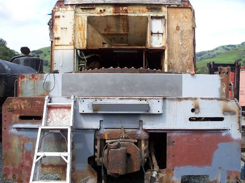
The new front MU box was also ready to be attached in the SP's raised position. Howard made a temporary bracket for the back side to locate it correctly, plus give it something to hang from, since it's one heavy little dude. Welding the lower face of the bracket was a challenge because of the angle, and an example of how some easy-looking restoration tasks aren't always that easy. When Howard was done, it was straight as a die and restored to exactly how the SP placed it in 1964. The First Official SP K-M Modification (so far as we know) is re-created.
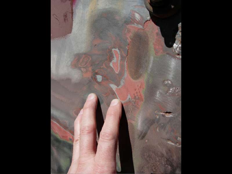
Very interesting what was under all that paint thickness. Looks like K-M used aircraft-style zinc chromate or zinc phosphate primer (green) and then a coating of what's commonly called 'red lead' primer after that. Then a light gray surfacing prime coat, and then the final Lark Dark Gray. There's at least one SP-applied coat of Dark Gray after that, and likely another coat of SP primer beneath that. It's going to take some elbow grease and time to get all this buildup off the whole locomotive. But for now, the front end is shaping up right along with the new nose.
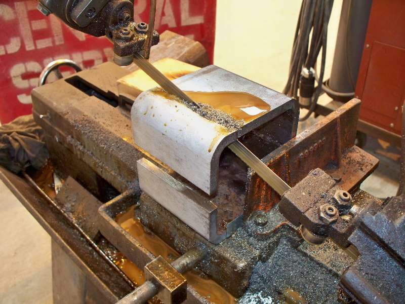
-- Update June 04, 2009 -- The brackets that support the front hand rails on the cab end were removed during the Camera Car conversion. While not exactly part of the front end, they are needed to attach the new hand rails that we will be making. I believe that the original brackets are forged and luckily, the brackets on the rear of the cab are still there.
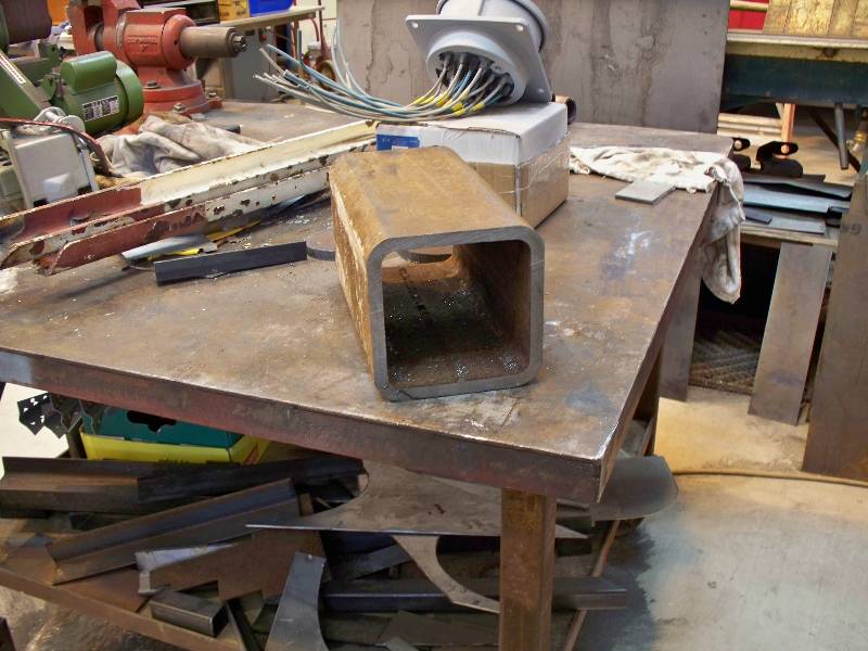
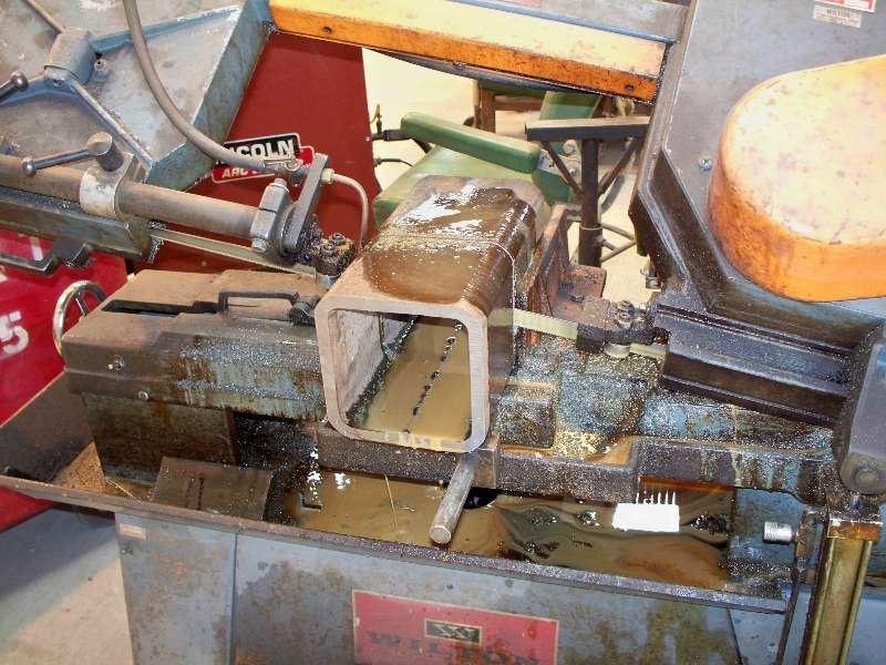
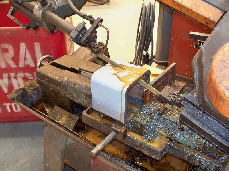
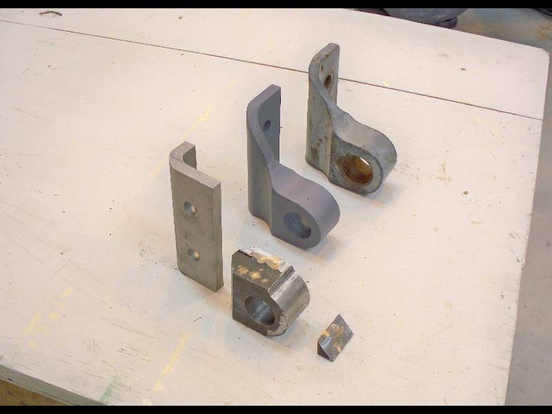
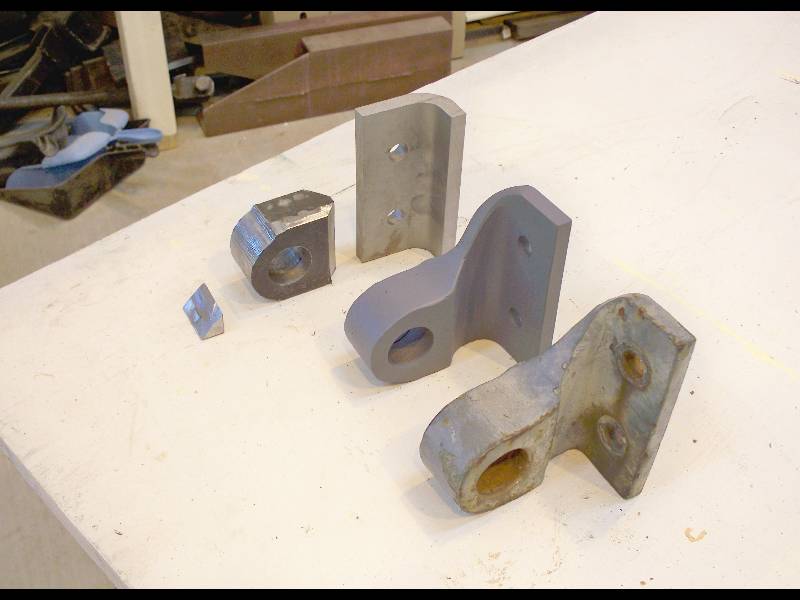
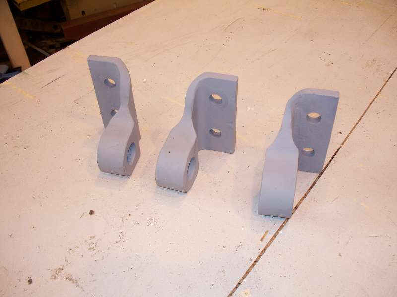
The section and radius of the bracket looked to me like that of a piece of 1/2" square tubing so a piece of 5" was obtained and cut apart.
The part with the hole is made from a piece of bar 2 1/2" by 1 1/2" with a hole 1 5/16" drilled through. Our machinist Jeff Coker saved me a ton of work by milling the radius on the ends of the pieces. Their bases were ground to shape and welded to the angle pieces. The piece on the right is an original from the rear of the cab which is being used as my pattern. In the first and second photos, the angle piece on the left is not in the correct relationship with the hole piece as I screwed up the pose but they were welded together correctly.
-- Update September 18, 2009 -- Our newest crew member Dan Furtado is hard at work grinding old welds on the front end. Dan's talents with metal are certainly welcome on the project. In addition, Jon Vlasak completed the piping to the MU hose elbows on the left side.
-- Update November 07, 2009 -- Before Dan could continue working his magic on the front end, I had to weld the right side MU hose support plate to the front sheet. Once I was out of the way, Dan worked over the air arc gouges left from years past. He also cleaned up the openings for the step lights.
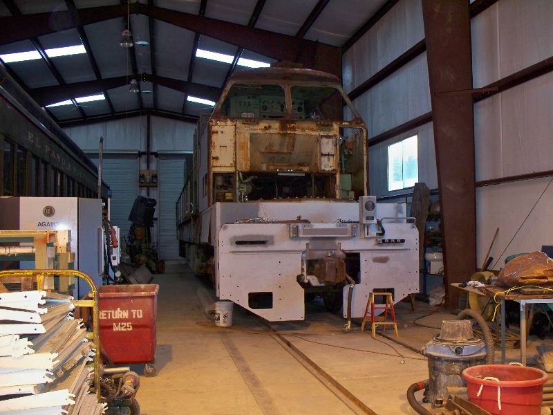
-- Update December 29, 2009 -- The big news for this update is that we were able to move the 9010 into our shop building so that work could continue on the front end during at least part of the winter. Our GM Dexter Day was instrumental in making this happen for us.
Once in, Jon and Gerry removed the tarps and plywood coverings so we could start cleaning up the cab. I was able to complete the installation of the MU box on the front end and will soon route the wiring up to the MU connector. Some of the brackets for the handrails also went on as well as one of the upper grab irons and the MU step was test fit.
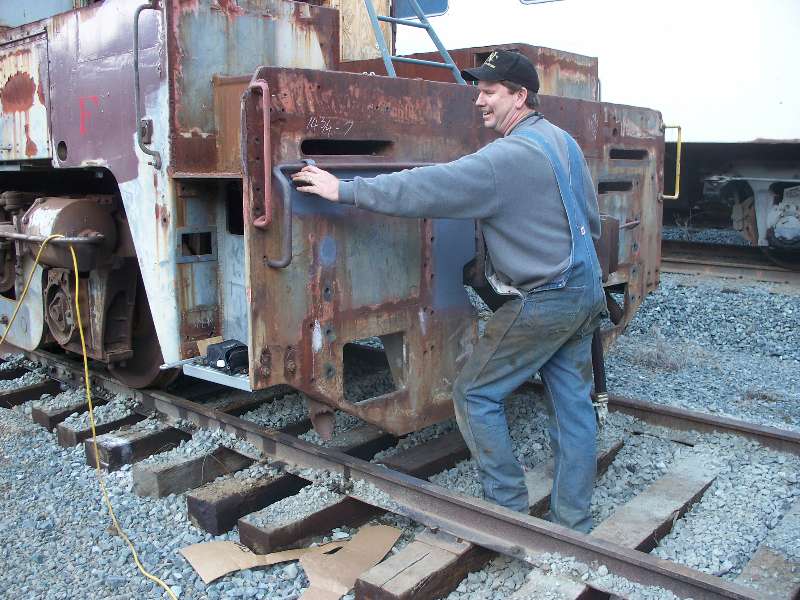
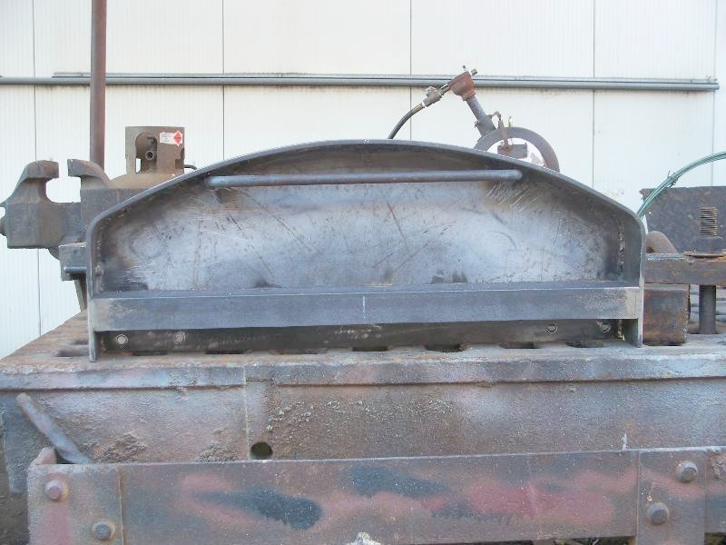
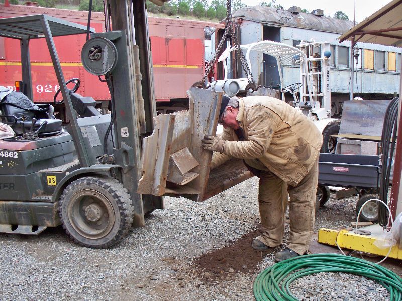
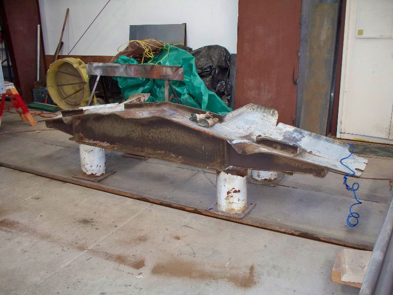
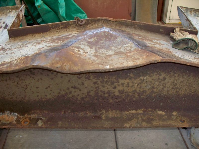
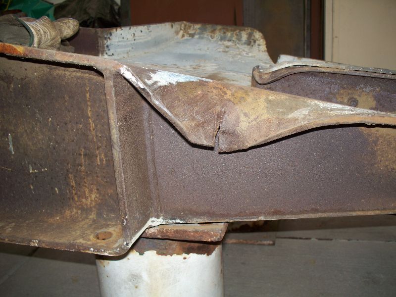
Another big event was the removal of the rear pilot. The intent is to repair damage to its lower surface and install it on the front. First below is a photo from Krauss-Maffei of the SP 9003 while on the erection floor. The locomotive was not released from production like this but, it gives us a model for the rear end since duplicating the correct pilot would not be practical and, the rear end will almost always be coupled to another locomotive. Rich Alexander gave a big assist in the pilot swap and elected himself to clean out the crap lodged inside the pilot frame. Once brought around to the front end, the pilot was hung in place to check bolt alignment.
After we verified that it was going to fit the front end, it was removed and set on stands for some surgery. As you can see, the pilot has suffered many indignities in its 45 years of life.
|