Southern
Pacific 9010
Mechanical Work
Page 1
Page 1
-- Update June 13, 2010 --
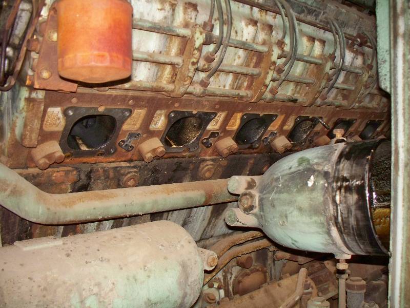
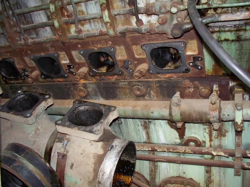
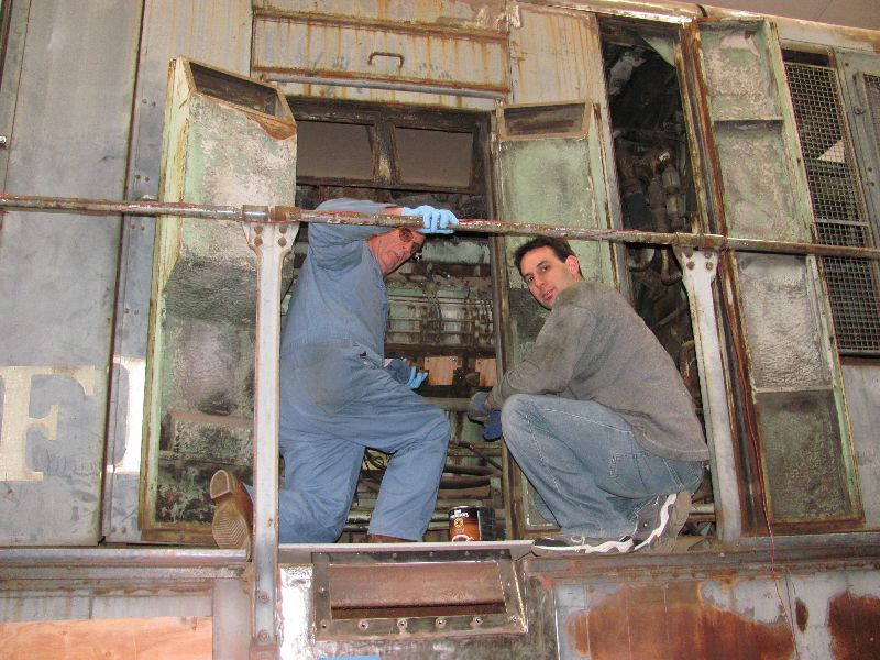
Our friend and 9010 crew member Rob Fern came over from the UK for a week and took the lead investigating the condition of the number 2 Maybach diesel engine. Keeping in mind that it has been over 40 years (1968) since the engine last ran, we wanted to see if it could be turned over. There is no way to spin the motor with the starter as it is located on the transmission and there is no drive shaft between it and the engine. So, we came up with a way to bar it over using some bolts in the flywheel. First however, we got the prelube system running and piped some of the oil to the valve mechanism. We removed both of the intake manifolds in order to get at the cylinder compression release valves which were frozen solid. The valves were removed and we shot a goodly quantity of WD40 into each cylinder through its compression release port.
 |
 |
 |
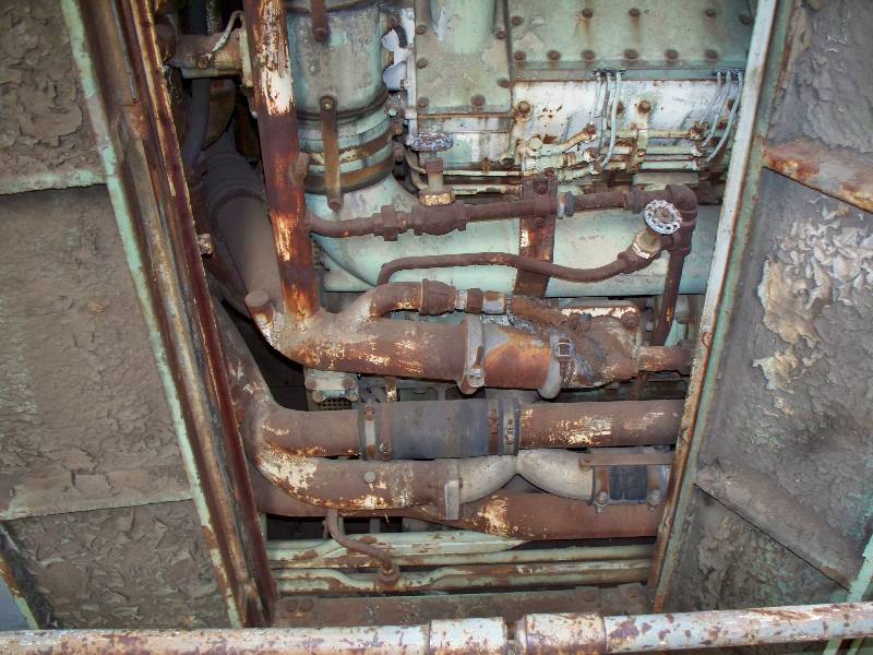
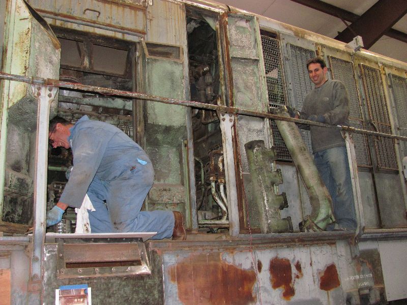
On the right side of the block, there is a lot of water piping in the way. It is obvious that Krauss Maffei never intended anyone to remove an intake manifold with the engine in the frame but, we had no option so off came the piping.
 |
 |
 |
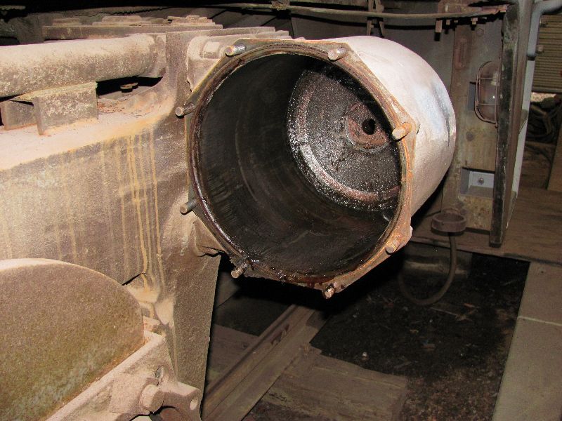
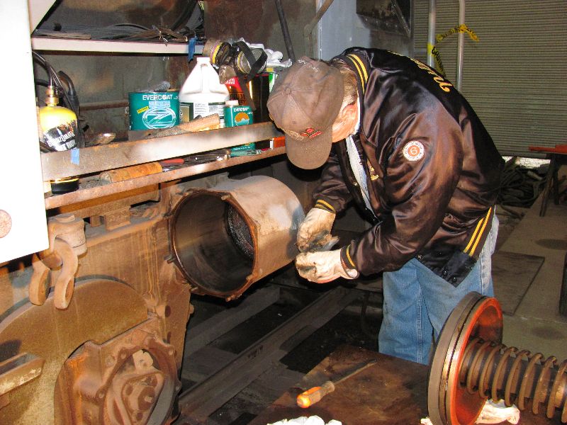
Rob suggested that it would be a good idea to look down into the two turbochargers to see if they were full of junk and most importantly, to find out if they would turn after 42 years. He and I removed the rotten flexible intake connections and found a screen over the intake which had kept a bit of junk from falling into the intake. With a little pressure (very little) the rear turbo turned with some resistance but no noise. The front turbo almost took Rob's fingers off as it absolutely spun when he tried to turn it. Surprise after surprise! Rob also removed the tops from the #1 engine turbos and found that the forward one was completely free while the rear one was stuck. He also cleaned out the intake areas of all 4 turbos with a vacuum cleaner.
 |
 |
 |
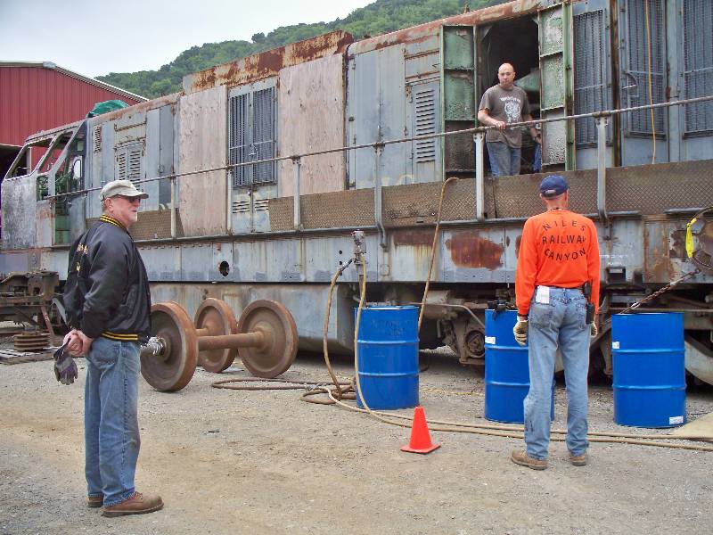
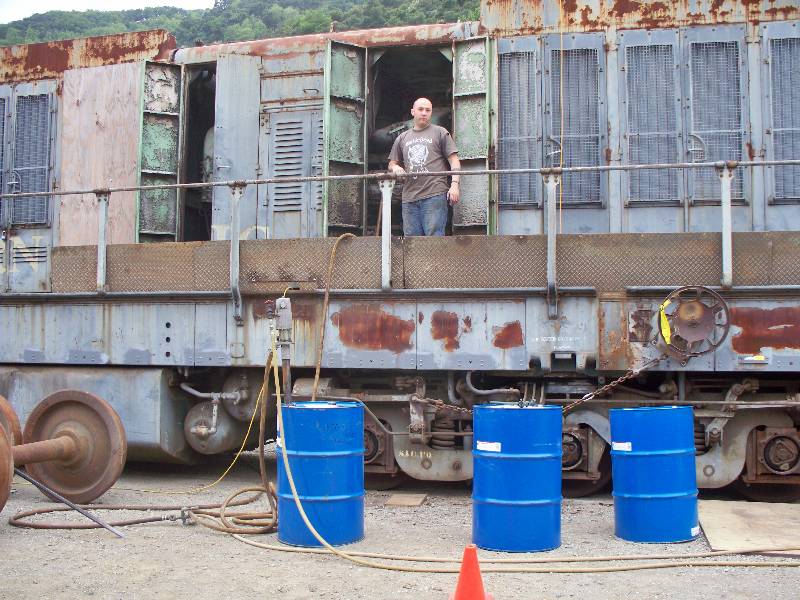
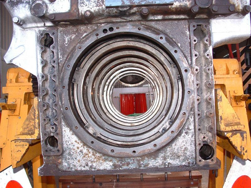
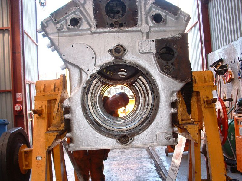
The Maybach has a roller main bearing crankshaft and there is no direct lubrication to the crank main bearings. We pumped 3 barrels of lube oil into the pan which raised the oil level high enough to put the bearings in the lubricant. This was possible because the roller bearing mains are nearly 15" in diameter. The two engine images illustrate the Maybach "tunnel" crankcase and the large hole for the crankshaft roller bearings.
 |
 |
 Terry
Deacon Photo
|
 Terry
Deacon Photo
|
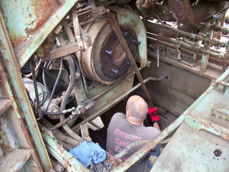
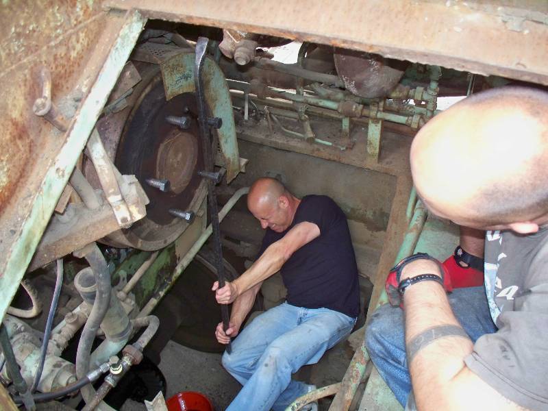
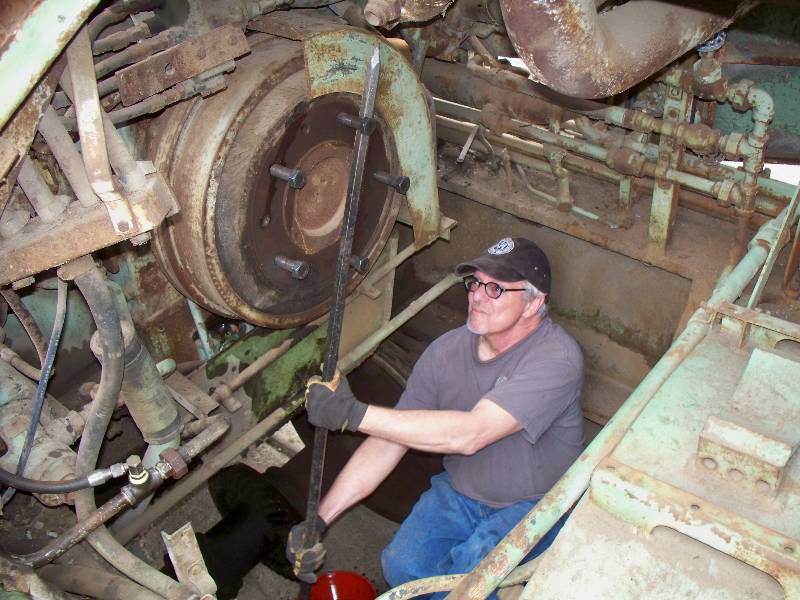
Once we had oil in the engine pan and it was being lubricated by the prelube pump, Rob climbed down on top of the rear truck and began to apply a steel bar to the bolts he had screwed into the flywheel. Now, keep in mind that this engine has been sitting out in the weather for the past 42 years and expecting it to move easily if at all was beyond our wildest imaginations. But, it did turn. And, it was not all that difficult. And there were no bad noises. There was one spot in the rotation that was resistant but we figure that was probably carbon in one cylinder (actually, #10) and after a few rotations, that resistance went away. We all had a turn at barring it over just for the sheer joy of doing it. Unfortunately, my turn was not recorded. You can click HERE for a short video of the process.
 |
 |
 |
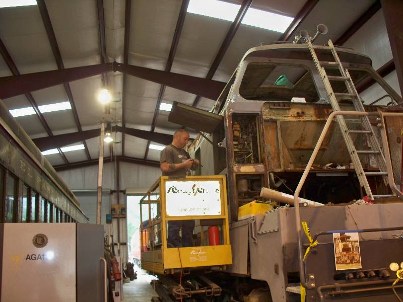
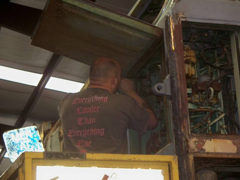
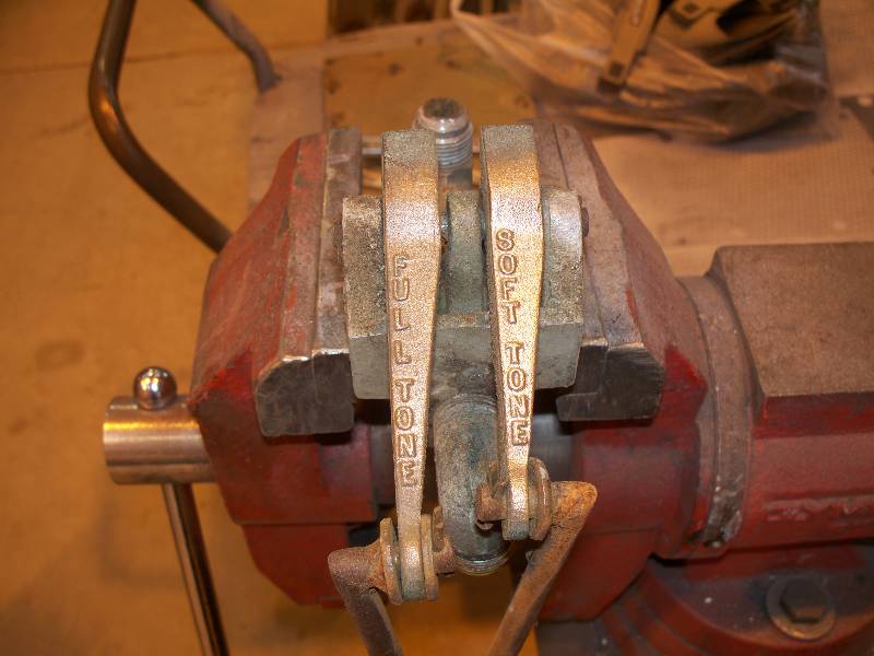
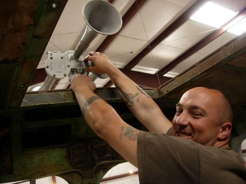
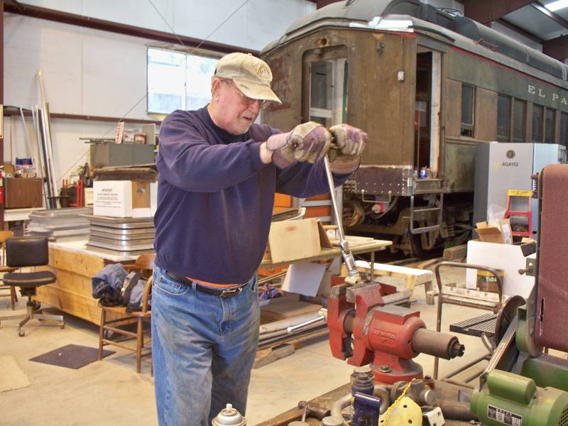
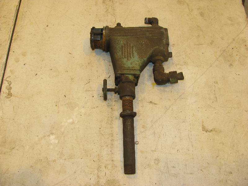
After our adventures with the engines, I took advantage of Rob's mechanical abilities and asked him to have a look at the horn valve. He wound up rebuilding it so it should be good for another 50 years. Needless to say, we had to temporarily mount the horn and try it out.
 |
 |
 |
 Bob
Zenk Photo
|
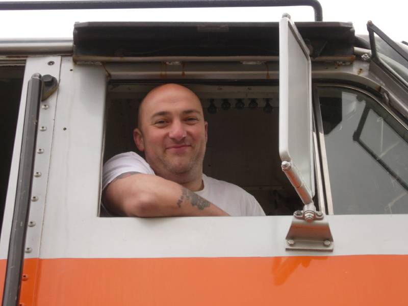
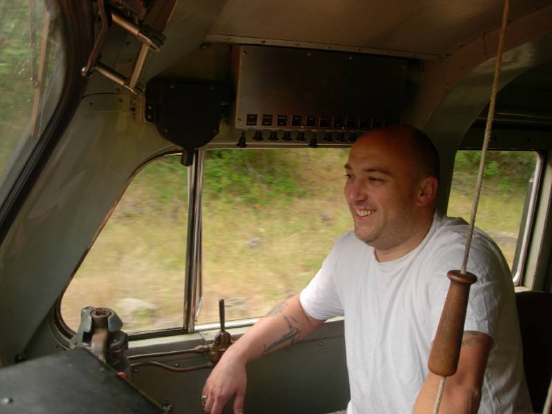
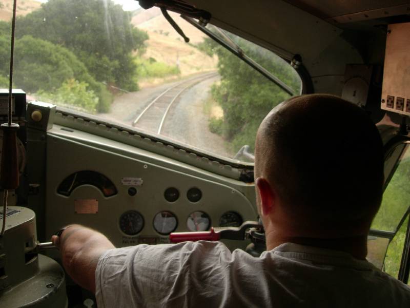
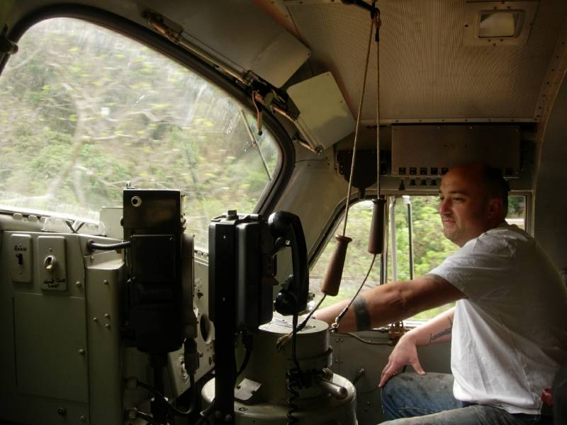
Rob took a bit of time out of Krauss Maffei work to try out the right hand seat of our WP918 F7. Being a "train driver" in the UK, it took him only a few minutes to adapt and enjoy the scenery of our railroad.
 Bob
Zenk Photo
|
 Bob
Zenk Photo
|
 Bob
Zenk Photo
|
 Bob
Zenk Photo
|
Rob had to return to the UK all too soon and those of us working on the 9010 and the other PLA members who met him will miss his knowledge, helpful spirit and sense of humor. Come on back anytime, Rob!
-- Update July 17, 2010 --
Work continues on engine parts. The compression release valves were taken apart, bead blasted, springs replaced as required and reassembled. Reinstallation on the engine completed this little chore. For now, there are plywood covers over each intake area.
 |
 |
 |
 |
-- Update June 09, 2011 --
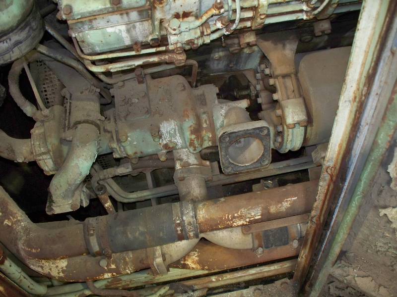
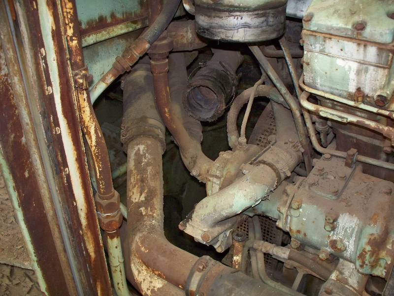
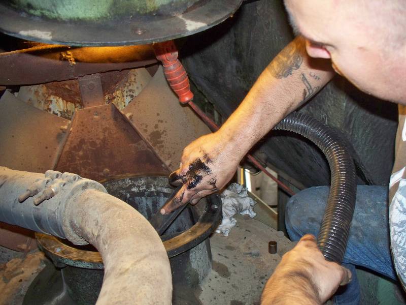
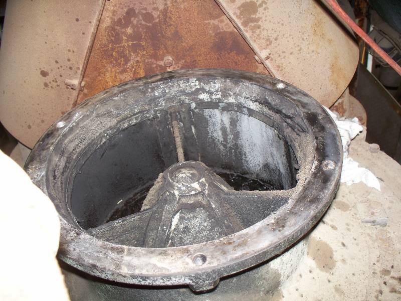
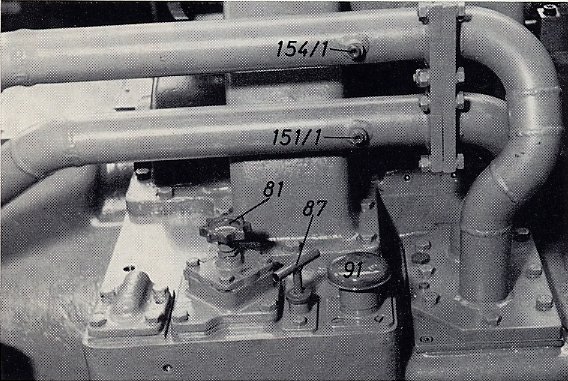
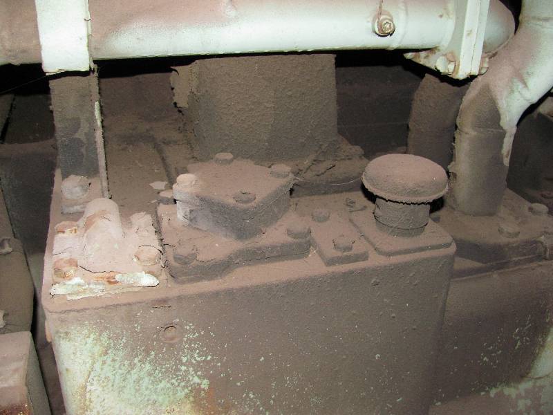
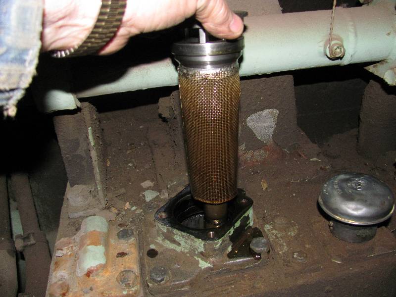
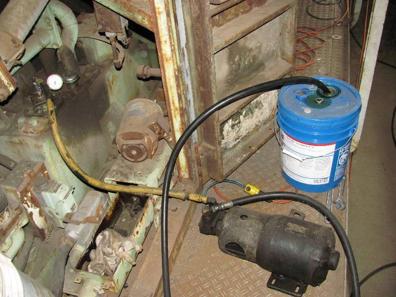
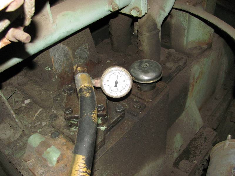
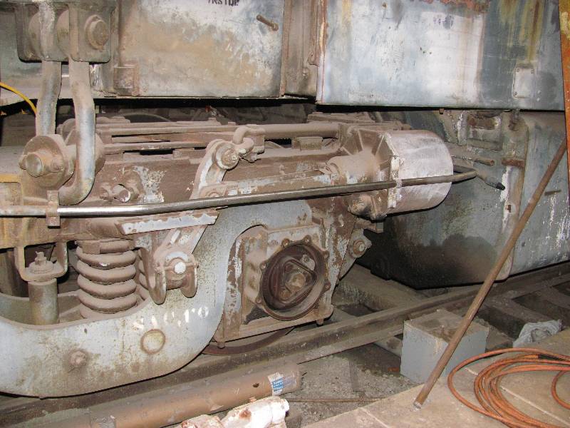
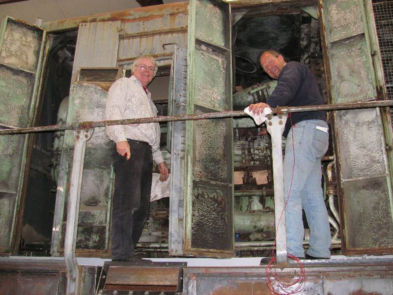
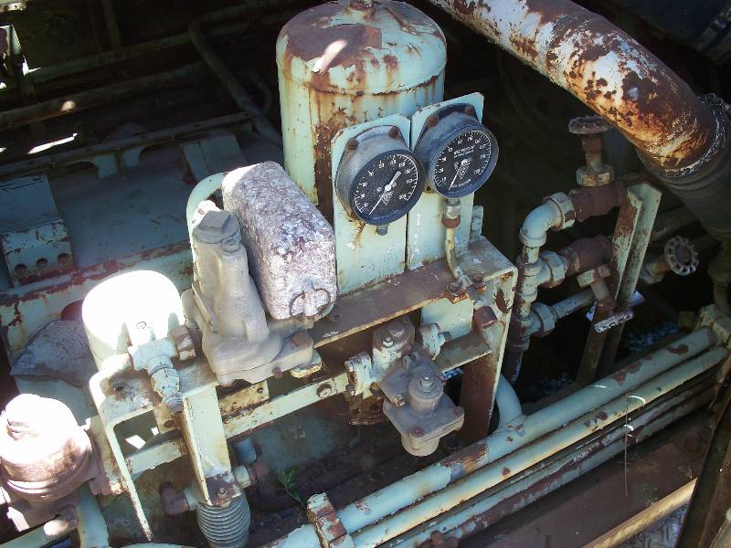
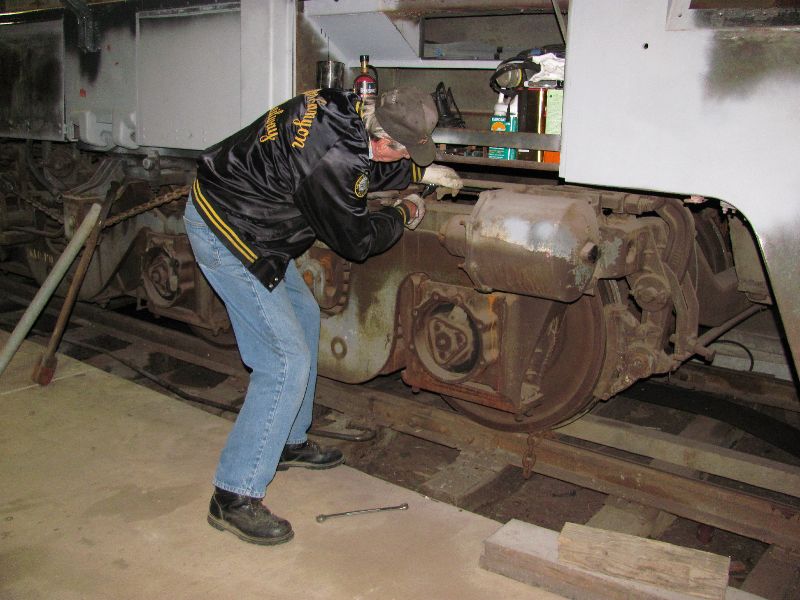
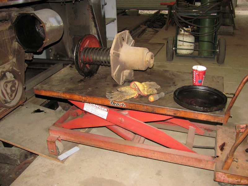
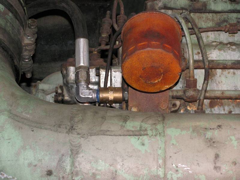
The 9010 is equipped with one remaining Voith transmission and we have been curious for some time about its condition. The engine starter motor (called a Dynastarter) is mounted on top of the transmission and thus cranks the engine through the transmission. Because of this arrangement, if the Dynastarter were to be spun, the transmission would be operated, just as though it were being powered by the engine. So, why not just connect a welder to the Dynastarter and power it up? Because CSRM drained the transmission fluid about 20 years ago. So, I set out to find a way to lubricate the bearings without operating the main oil pump. The transmission holds about 200 gallons of oil and there are better uses for our funds than filling that big box right now. Checking the Voith section of the KM service manual revealed that the transmission has 2 oil pumps, one of which lubricates only the bearings through a filter. In searching out the best place to tap into the bearing lubrication system, I discovered that someone had modified a number of things. Item 81 in the first photo is a special type of filter called a "Lamellar" filter which has a knob that is to be turned to scrape any crud off of the filter and into a housing where it can be removed. The Lamellar filter was replaced with a simple screen. Also note in photo 1 the presence of item 87 which is the dip stick. It was moved to the other side of the transmission, perhaps so it would be on the same side as the engine dip stick. The flat cover over the screen filter presented me with the ideal place to attach a fitting for an oil pump.
 Krauss-Maffei
|
 |
 |
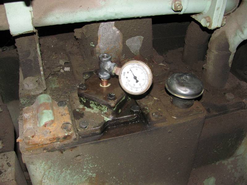 |
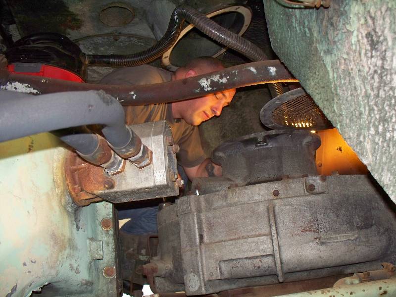
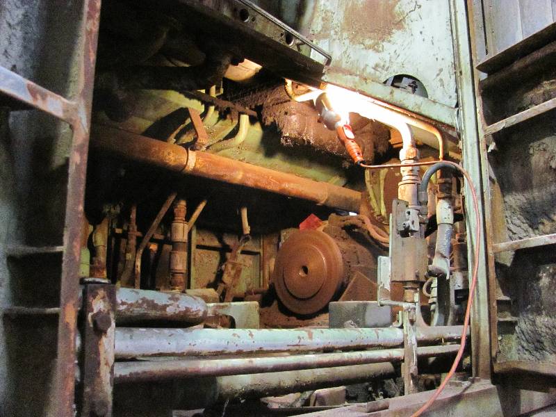
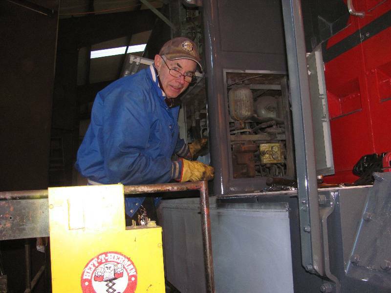
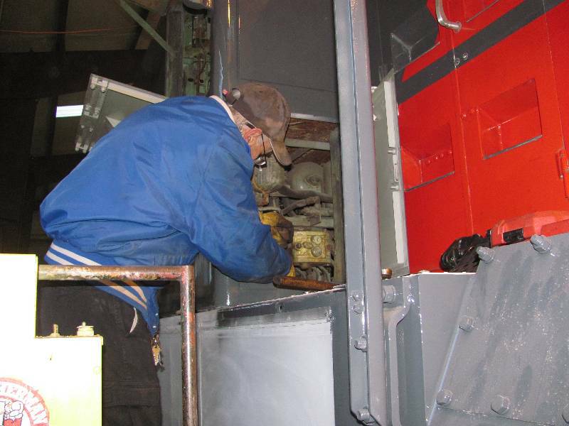
Our friend Rob Fern came from the UK to visit and we put him to work on the transmission mini-project. We purchased 10 gallons of transmission fluid and began pumping it into the bearings. Once the oil pressure came up, we connected a welder to the Dynastarter and hit the switch. You will note the blurred appearance of the transmission input flange in the third photo. This blurring it due to the rotation of the shaft. We were extremely pleased with the ease with which the transmission spun and the near total lack of noise while it was spinning. This little adventure leaves us with one less unknown item on our KM check list.
There are two short videos of the operation on YouTube at
"Spinning the Voith, Part 1" and "Spinning the Voith, Part 2"
 |
 |
 |
-- Update August 12, 2011 --
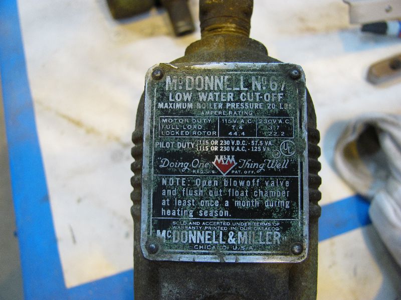
Mike Brodie removed the water level sensor from the rear radiator top tank so we could check it over and clean it up. When we took a good look at it, we found it to be of American manufacture. Given that it is covered with green paint, we figure that it was a replacement installed at or before the 1966 R7 rebuild. He is also plugging pipes preparing for a water pressure test of the top radiator tanks. We don't want to find out that they will not hold water after the roof is painted. Mike B. is a trained diesel mechanic and a very welcome addition to our crew.
 |
 |
 |
-- Update September 01, 2011 --
Our friend Carl Peter Zander solved the little mystery of the US made low water device mentioned in the previous update. His welcome email included the following information:
"The 6 prototypes were equipped with the Bopp & Reuther device, which was standard in the German Railroad DB. This was a very sophisticated device using mercury to compensate the static water pressure. SP did not like this, and asked for an US maker, whose name I have forgotten. This device was very simple; a cylindrical tube of 4 or 5 inch dia and aprxm. 8 to 10 inch long. On the side two pipe connections and in the top cover, sealed under a rubber sheet an electrical switch, which was actuated by a floating ball of aluminum, which had enough clearance within the cylinder. In case the water level dropped, finally the switch tripped. After only a few months of operation, there were many failures: the hollow balls became leaky and sunk, maybe they were shaken to much, furthermore there were some malfunctions of the switch. At first the balls were replaced, but the situation became not any better. In summer 1964 SP gave the order to install the McDonnel Low water cut off devices. These worked without any complaints."
-- Update September 28, 2011 --
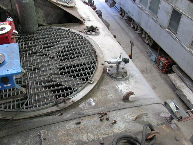
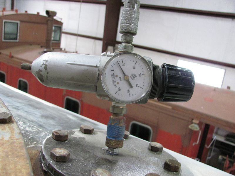
The curved edges of the cooling section roofs are actually the top tanks of the radiators. We decided to make sure that these tanks for the #2 engine are water tight. The easiest way to do this is to plug all the piping and other holes and then put air in the system. The tanks are separated in two sections, one for the turbocharger aftercooler and the other for the engine. They were individually pressurized to 7 PSI (the pressure of the radiator caps) and the entire outer surface checked with soapy water. We found many cracks in the steel which were no doubt caused by the welding of the "humps" on the curved surfaces. Eventually, all the leaks were eliminated and the body work has begun.
 |
 |
-- Update November 21, 2011 --
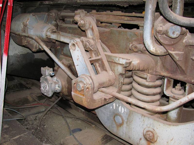
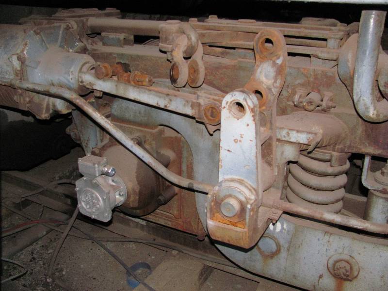
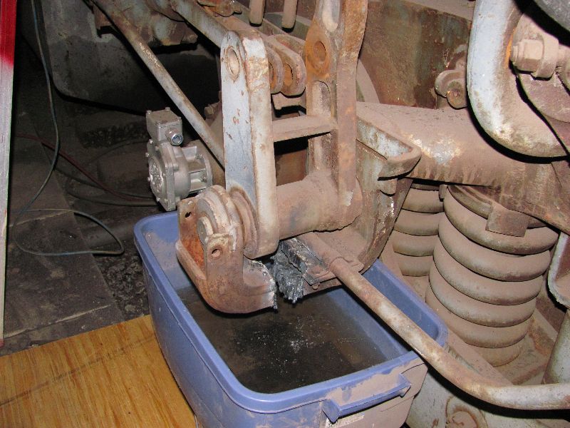
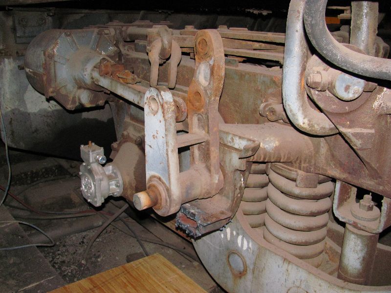
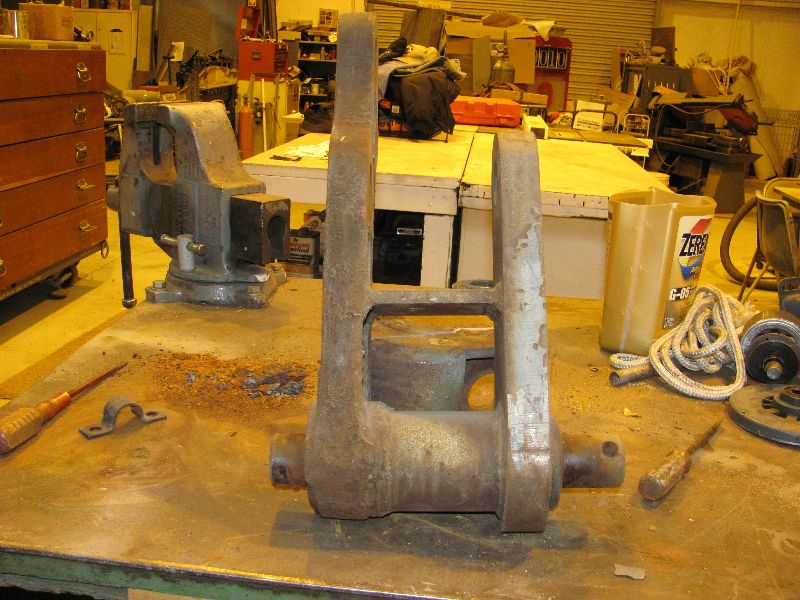
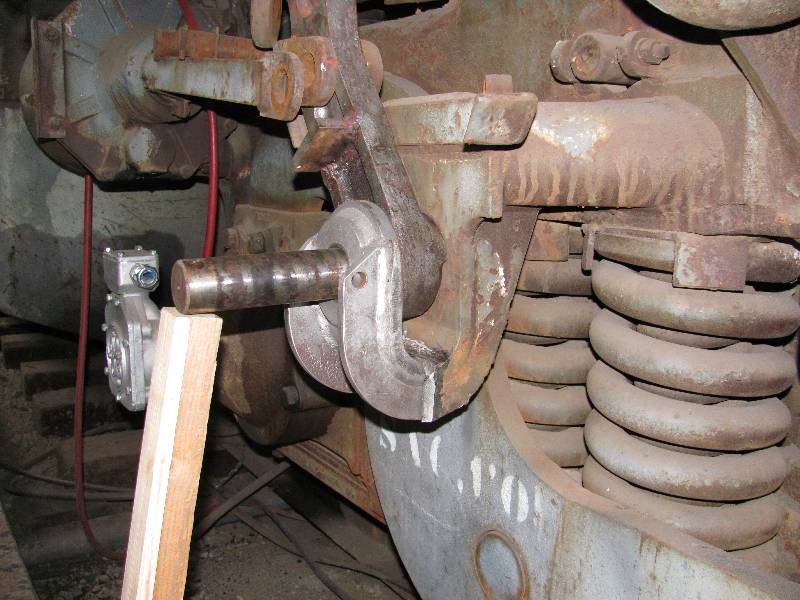
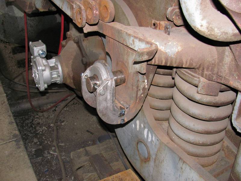
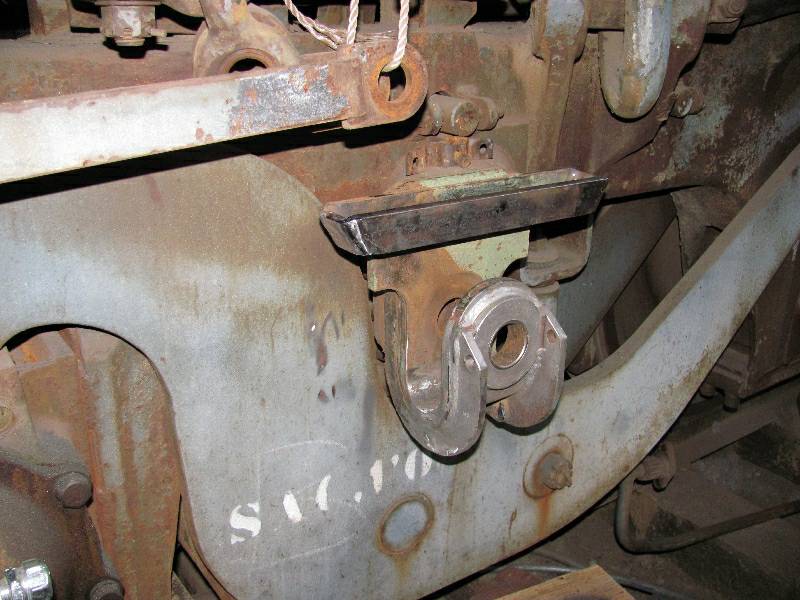
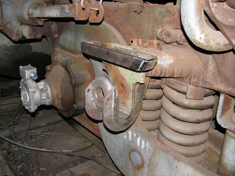
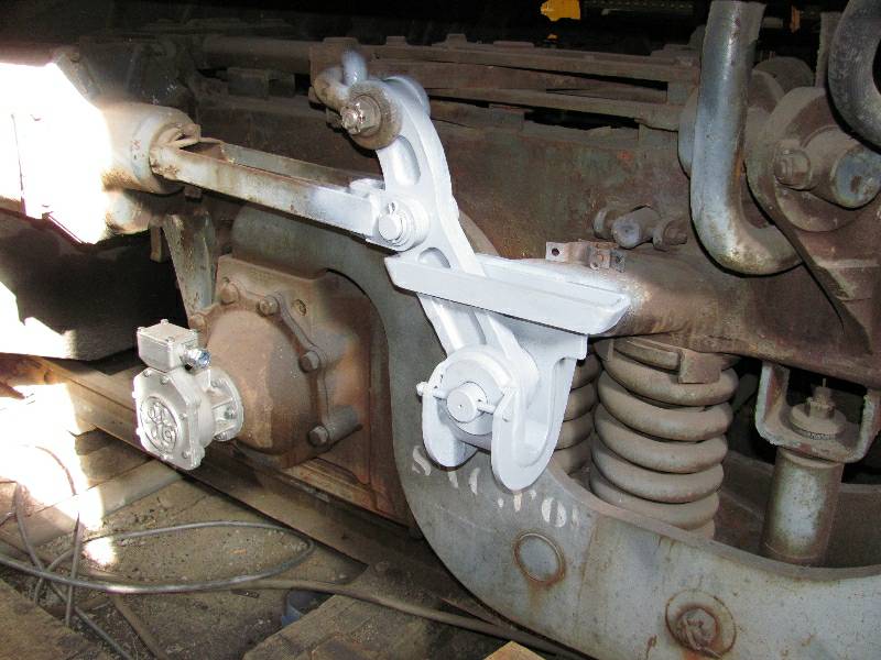
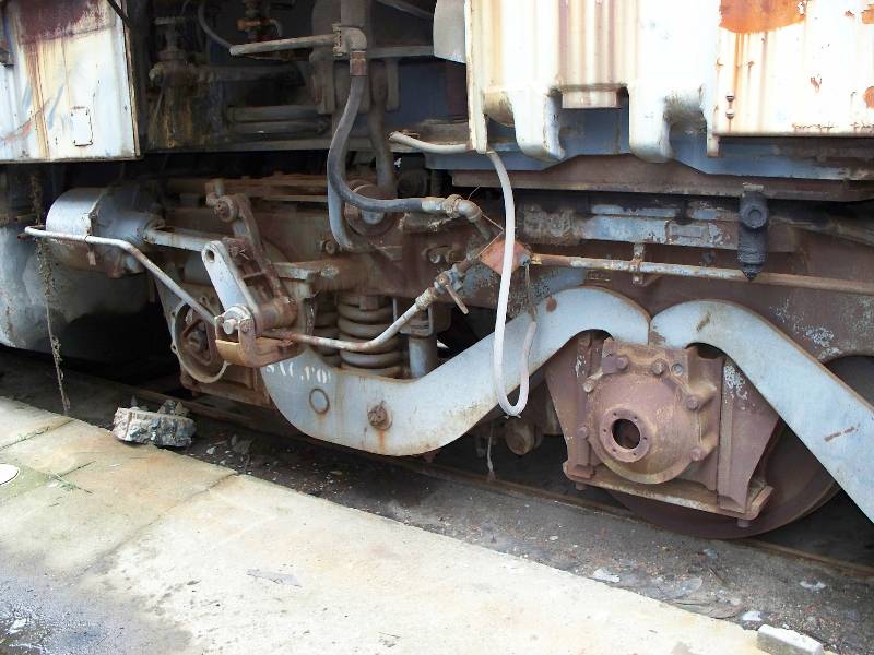
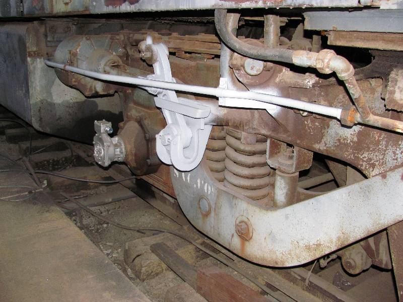
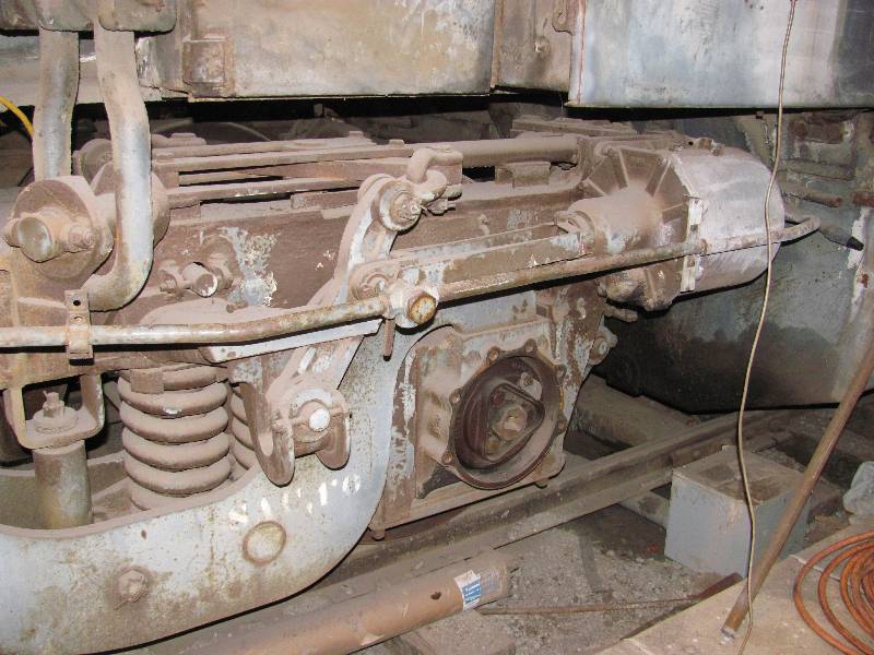
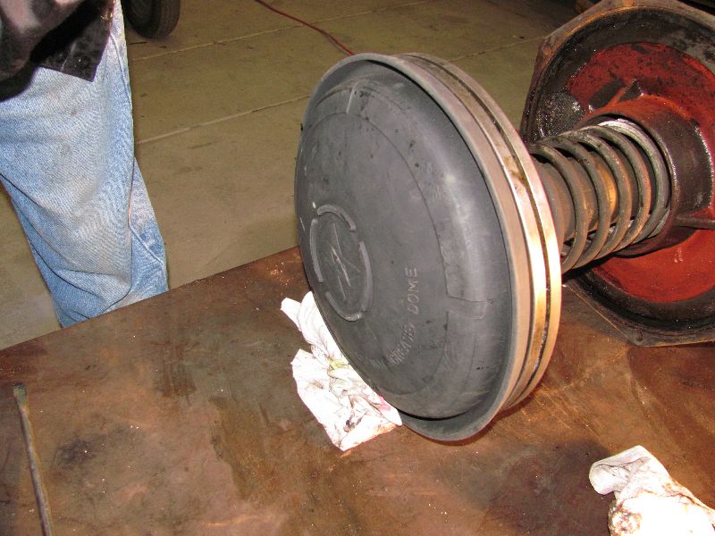
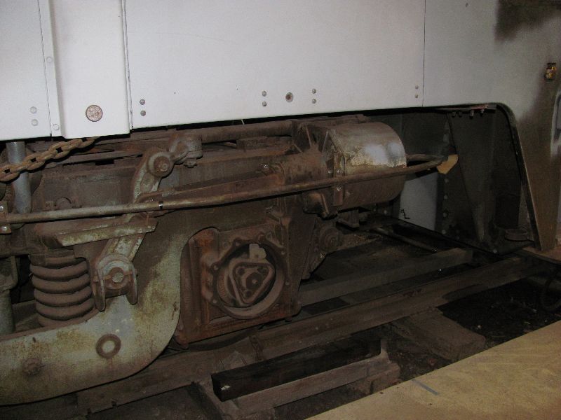
When the SP moved the hand brake to the right front corner of the 9010, they modified the front truck to provide a new attachment point for the chain and a roller to guide the chain. The roller and its bracket were torched off during Camera Car conversion but, the linkage modifications remain. This has to change as not only are the parts unneeded but the desire is to return the truck to its original appearance. Photo 1 is of original linkage, photo 2 is the brake as applied in Sacramento, photo 3 and 4 are of the modified linkage.
 |
 Otto
Baumgartner Photo
|
 |
 |
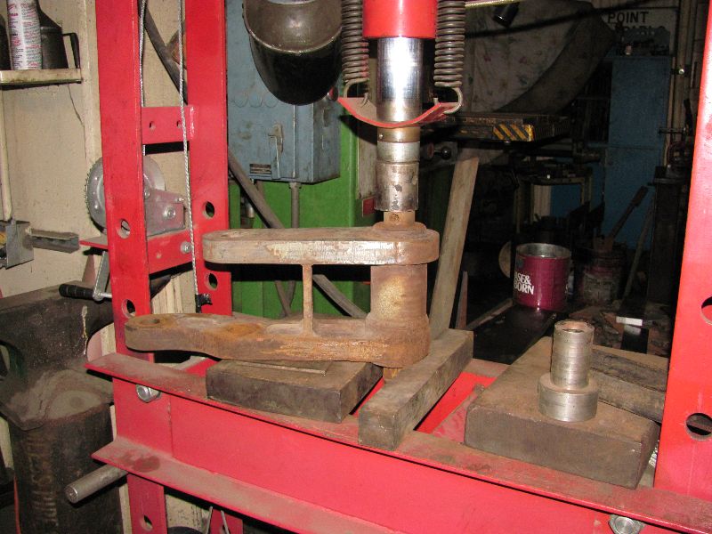
The shaft was frozen inside the modified arm which required that the bracket be cut in half with the gas ax in order to remove the arm from the frame. Then, the pin was pressed out of the arm with 35 tons of hydraulic pressure.
 |
 |
 |
 |
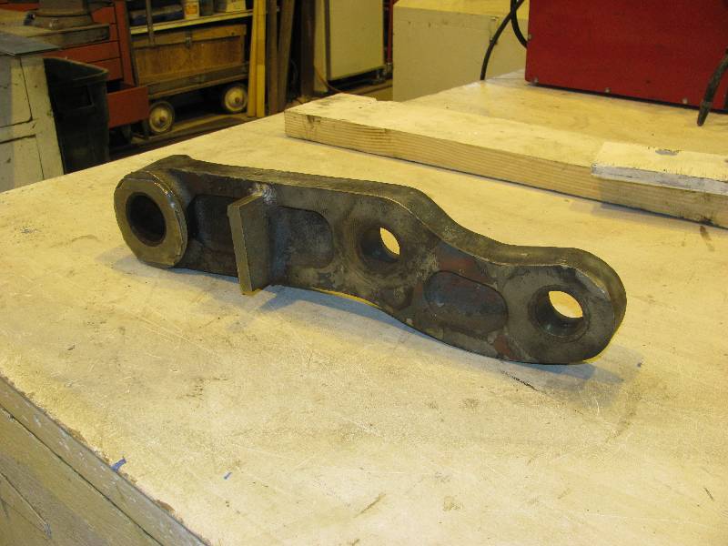
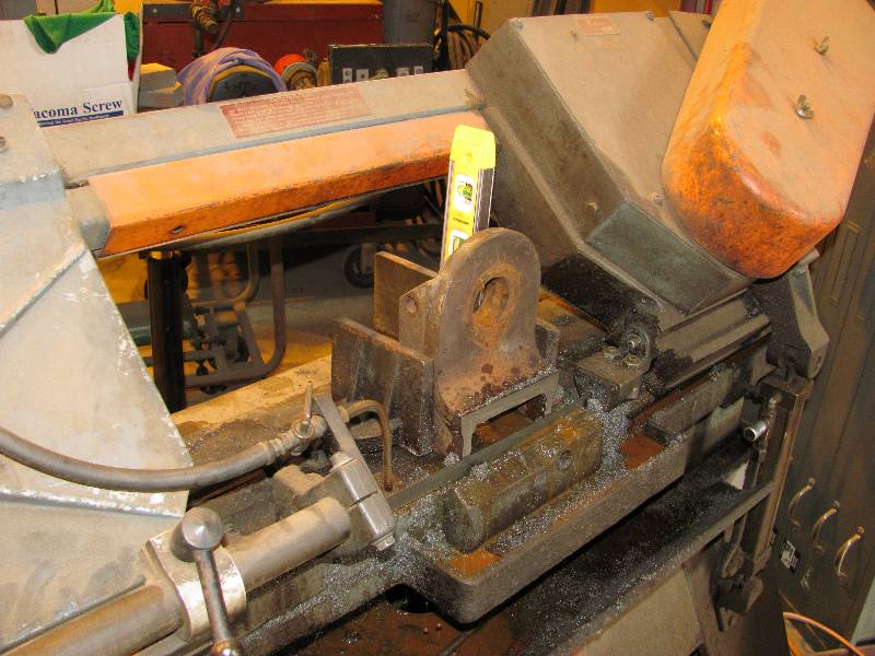
Once the pin was out of the way, the added pieces were cut from the brake arm. The excess metal was cut from both halves of the bracket and the resulting pieces welded back together.
 |
 |
 |
 |
I replaced the missing piece of guide above the bracket, did a bit of grinding on the bracket and re-installed all the brake linkage. All that remains is making a new brake cylinder pipe.
 |
 |
 |
-- Update December 08, 2011 --
It was necessary to change the fireman's side rear brake cylinder pipe as there was a cylinder cut out valve that had to be removed. Below are before and after views of both sides.
 |
 |
 |
 |
--Update April 16, 2012 --
Sometimes, things take much more time than expected. When Rob Fern was here in June 2010, we removed the compression release valves and intake manifolds from the number 2 engine so that we could squirt oil into the cylinders. Now, in 2012, those parts were still off, that is until his past weekend. Our friend Dave Hambleton and his dad Tom came up to spend the day and put all those errant parts back on the #2 Maybach. Their efforts were greatly appreciated.
 |
 |
--Update May 04, 2012 --
We had a surprise visit from a couple of project friends from the UK! Paul Koch and Andy Venn spent the day discussing Maybach engines, Voith transmissions, electrical systems and Krauss Maffei products in general. They are involved with a preservation group in the UK Diesel Traction Group and have a lot of experience with diesel hydraulic locomotives. They elected to get themselves dirty by having a look at the valve gear on the left side of the #2 engine. Their help and technical expertise made for a very interesting and informative day.
 |
 |
--Update
August 01, 2012 --
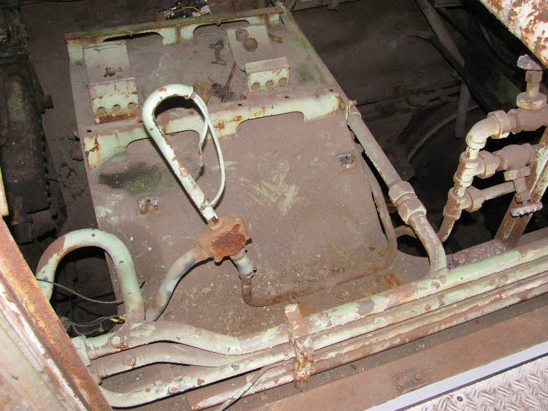
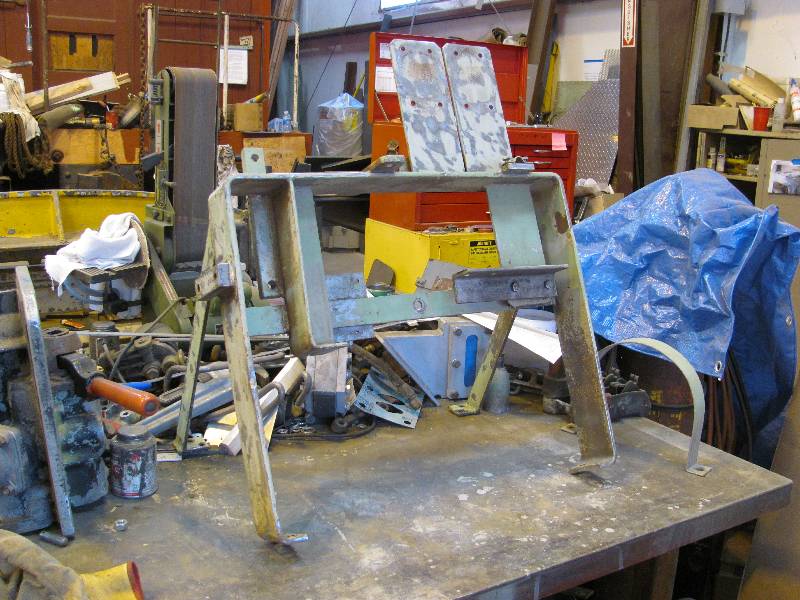
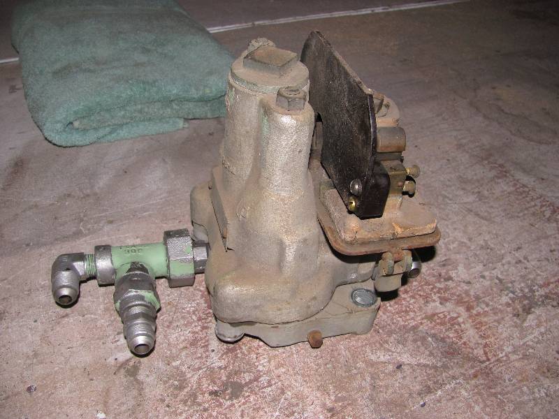
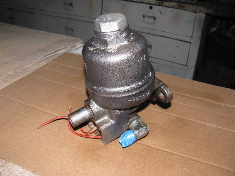
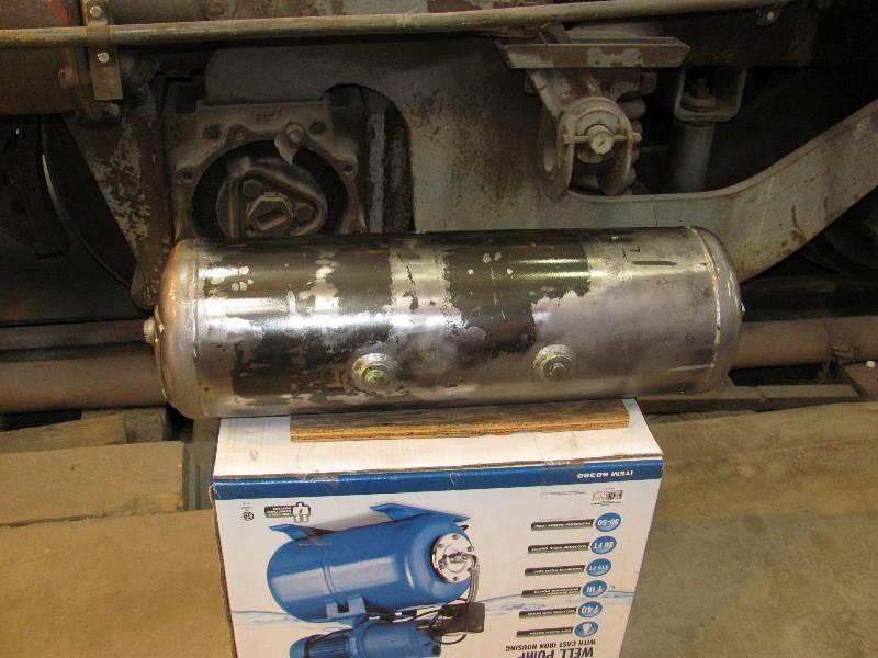
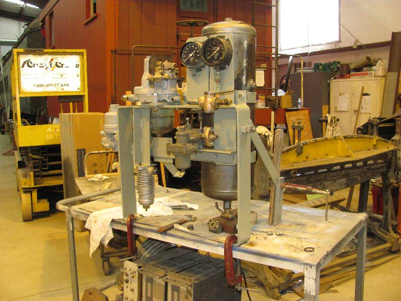
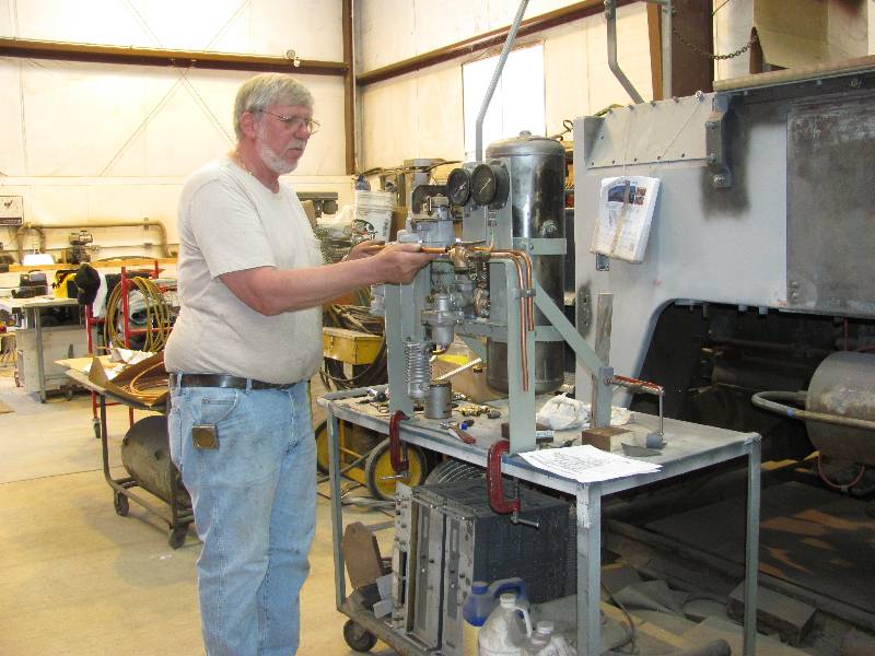
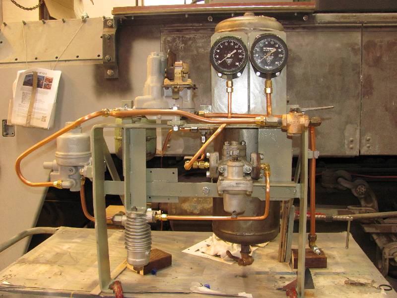
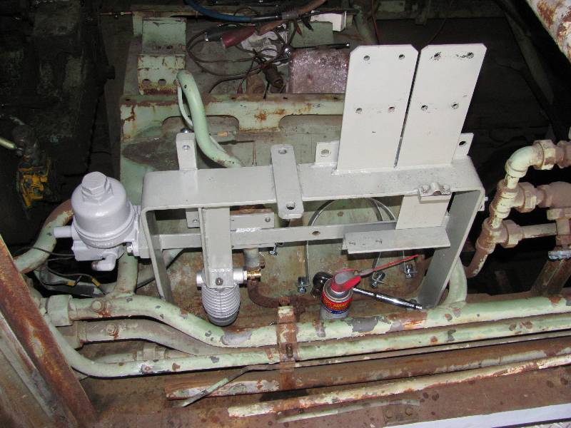
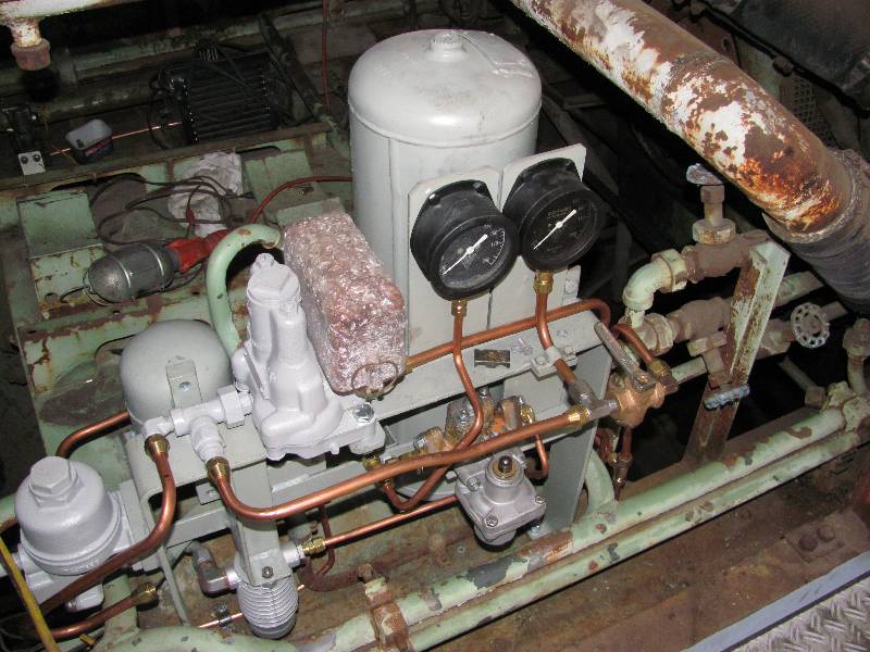
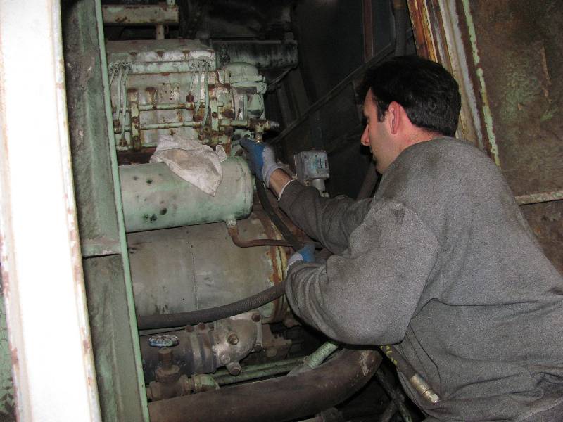
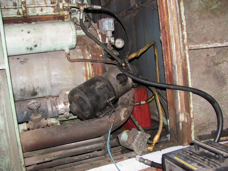
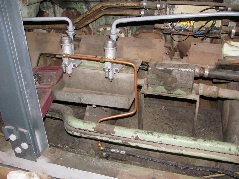
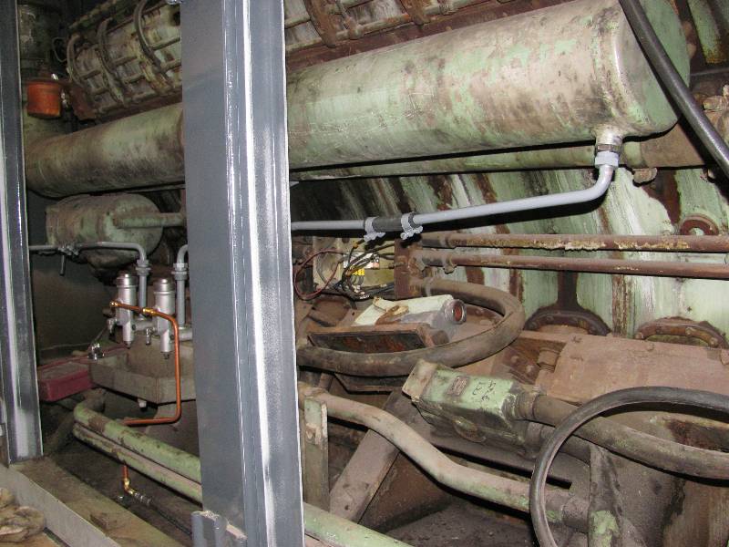
When the 9010 was in residence in Sacramento, the local copper thieves had a field day with much of the copper tubing at the rear end of the locomotive. One area that particularly suffered is the control air and compressor unloader. Control air is a source regulated to 90 pounds which is used on all the magnet valves on the engines and transmissions. The compressor unloader controls whether the air compressors are pumping or not. Both the control and unloader circuits are located on a rack on the right side, just forward of the rear transmission. I removed all the components and then the rack in order to clean the area and the parts more easily. First photo is the rack with parts intact and tubing missing. #2 is the area where the rack normally sits. #3 is the rack on the welding table, ready to be sand blasted. #4 is the compressor unloader valve. #5 is the relay valve used to synchronize compressors in the MU consist. #6 is the control air tank. #7 is the rack ready for piping. #8 is Bill creating new lines for the systems and #9 is the rack, tested and ready to be installed. The last 2 photos are of the rack back in place and connected to the locomotive.
When the 9010 was in residence in Sacramento, the local copper thieves had a field day with much of the copper tubing at the rear end of the locomotive. One area that particularly suffered is the control air and compressor unloader. Control air is a source regulated to 90 pounds which is used on all the magnet valves on the engines and transmissions. The compressor unloader controls whether the air compressors are pumping or not. Both the control and unloader circuits are located on a rack on the right side, just forward of the rear transmission. I removed all the components and then the rack in order to clean the area and the parts more easily. First photo is the rack with parts intact and tubing missing. #2 is the area where the rack normally sits. #3 is the rack on the welding table, ready to be sand blasted. #4 is the compressor unloader valve. #5 is the relay valve used to synchronize compressors in the MU consist. #6 is the control air tank. #7 is the rack ready for piping. #8 is Bill creating new lines for the systems and #9 is the rack, tested and ready to be installed. The last 2 photos are of the rack back in place and connected to the locomotive.
 |
 |
 |
 |
 |
 |
 |
 |
 |
 |
 |
--Update
December 07, 2012 --
There have been many small jobs begun and completed over the past 4 months, most of which have gone un-documented. One that did get a little photographic notice was the changing of a piston cup on the left #4 brake cylinder. The work consisted of removing the piston, cleaning the interior of the cylinder and end of the piston, removing the old, crusty cup, installing a new cup, putting the piston back in the cylinder and reinstalling all the parts. The 9010 has 12" diameter brake pistons which are a bit hard to handle, especially compared to the 9" pistons found on EMD locomotives but Rich and I managed to take care of the job without hurting ourselves.
There have been many small jobs begun and completed over the past 4 months, most of which have gone un-documented. One that did get a little photographic notice was the changing of a piston cup on the left #4 brake cylinder. The work consisted of removing the piston, cleaning the interior of the cylinder and end of the piston, removing the old, crusty cup, installing a new cup, putting the piston back in the cylinder and reinstalling all the parts. The 9010 has 12" diameter brake pistons which are a bit hard to handle, especially compared to the 9" pistons found on EMD locomotives but Rich and I managed to take care of the job without hurting ourselves.
 |
 |
 |
 |
 |
 |
--Update
December 15, 2012 --
When the 9010 was put of out service for conversion to the Camera Car, the SP simply cut, disconnected or removed anything not required. This included the fuel connections to the #2 Maybach. For some time, I have wanted to clean out the fuel lines and circulate fuel through the injectors. A couple of months ago, Dave Hambleton came up from San Jose for the day. He removed the fuel lines and cleaned them out which prepared us for the rest of the job. Dave came back up today (I had one of my rare Saturdays at the 9010) so we spent the day scrounging parts and hooking up a temporary fuel system. Fuel is drawn from a 5 gallon can, through a filter, through the pump, through the injection lines and back to the can. We put 3 gallons of fuel and some injector cleaner in the can and turned on the pump. After curing one small leak, we found that fuel was going exactly where it is supposed to go so now, I can run the pump now and then to keep the system clean. By the way, for any of you who know Maybach MD engines, the SP made some pretty serious modifications to the return side of the injection system. Why? We don't know but the piping now is somewhat like an EMD system.
Return To Main Page
When the 9010 was put of out service for conversion to the Camera Car, the SP simply cut, disconnected or removed anything not required. This included the fuel connections to the #2 Maybach. For some time, I have wanted to clean out the fuel lines and circulate fuel through the injectors. A couple of months ago, Dave Hambleton came up from San Jose for the day. He removed the fuel lines and cleaned them out which prepared us for the rest of the job. Dave came back up today (I had one of my rare Saturdays at the 9010) so we spent the day scrounging parts and hooking up a temporary fuel system. Fuel is drawn from a 5 gallon can, through a filter, through the pump, through the injection lines and back to the can. We put 3 gallons of fuel and some injector cleaner in the can and turned on the pump. After curing one small leak, we found that fuel was going exactly where it is supposed to go so now, I can run the pump now and then to keep the system clean. By the way, for any of you who know Maybach MD engines, the SP made some pretty serious modifications to the return side of the injection system. Why? We don't know but the piping now is somewhat like an EMD system.
 |
 |
 |
--Update
December 28, 2012 --
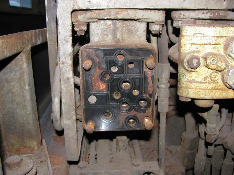
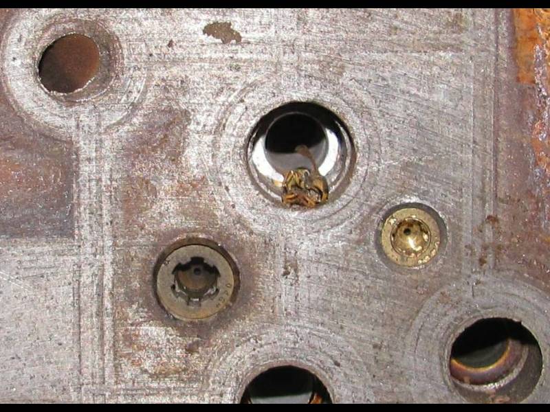
Gerry has taken on the job of getting and installing air brake components as testing has revealed a brake system that is decades out of date and barely functional. He found interesting little problems like dirt and a dead yellow jacket in on of the valve mouting plates.
Gerry has taken on the job of getting and installing air brake components as testing has revealed a brake system that is decades out of date and barely functional. He found interesting little problems like dirt and a dead yellow jacket in on of the valve mouting plates.
 |
 |
 |
 |
--Update
November 27, 2013 --
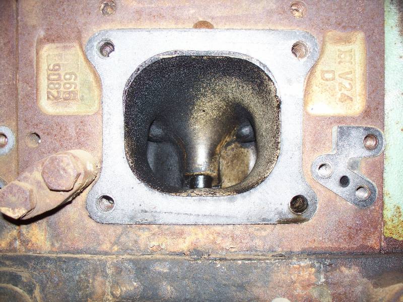
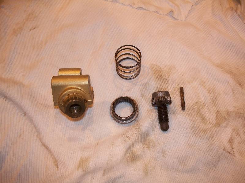
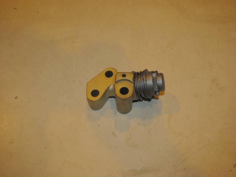
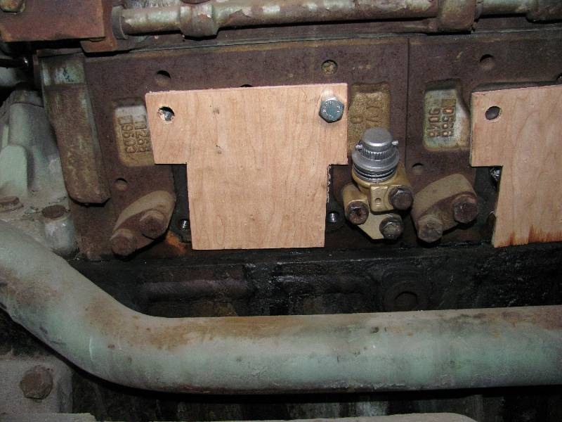
While in the process of working on the hood hinge posts, my attention was attracted by these gadgets. We learned from Richard Oed that this was a modification made to the engines by Maybach and installed by the Southern Pacific. These drains are open when the engine is idling and closed when the throttle is moved above run 6. Their purpose is to drain any liquid that might accumulated in the intake manifolds. Liquid from a coolant leak could rise in the manifold to a height sufficient to be drawn into a cylinder and cause a hydrostatic lock, destroying one ore more cylinders. The valves were plugged with carbon and just needed a good cleaning to make them operable.
While in the process of working on the hood hinge posts, my attention was attracted by these gadgets. We learned from Richard Oed that this was a modification made to the engines by Maybach and installed by the Southern Pacific. These drains are open when the engine is idling and closed when the throttle is moved above run 6. Their purpose is to drain any liquid that might accumulated in the intake manifolds. Liquid from a coolant leak could rise in the manifold to a height sufficient to be drawn into a cylinder and cause a hydrostatic lock, destroying one ore more cylinders. The valves were plugged with carbon and just needed a good cleaning to make them operable.
 |
 |
Return To Main Page