Southern
Pacific 9010
Mechanical Work
Page 2
Page 2
-- Update July 16, 2014 --
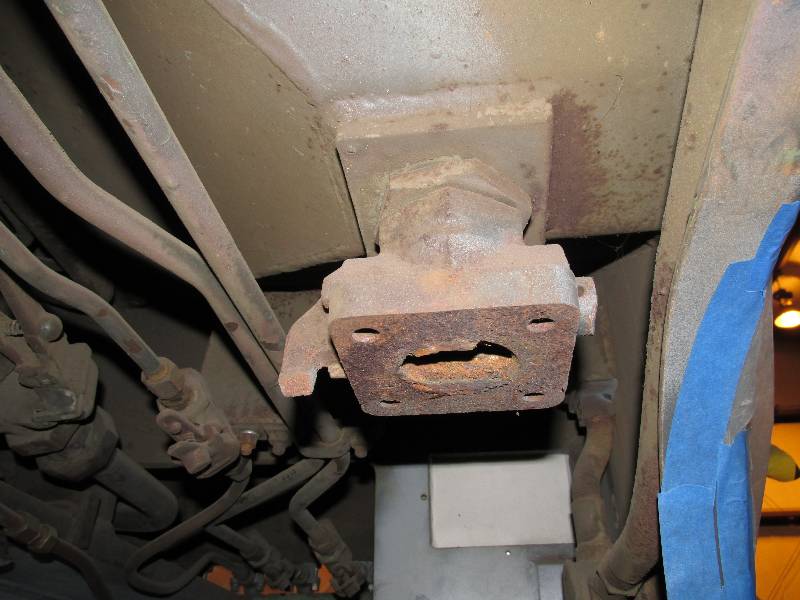
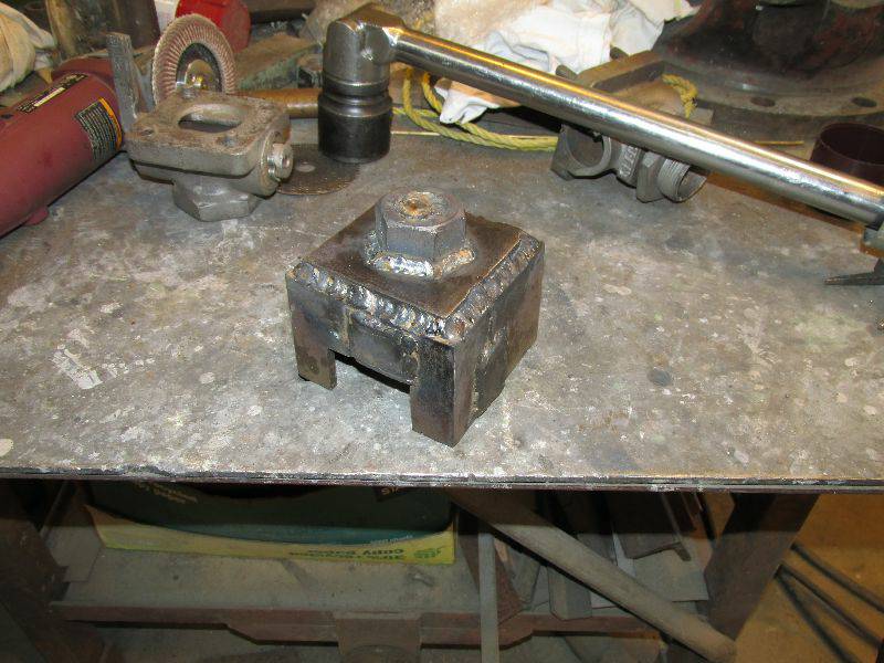
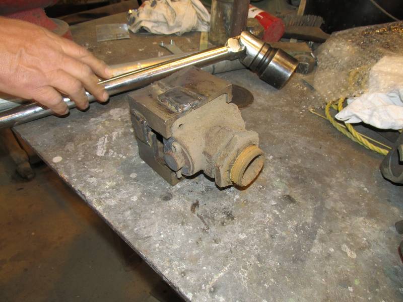
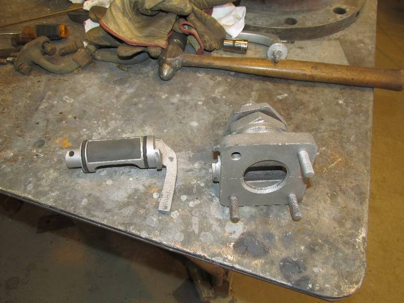
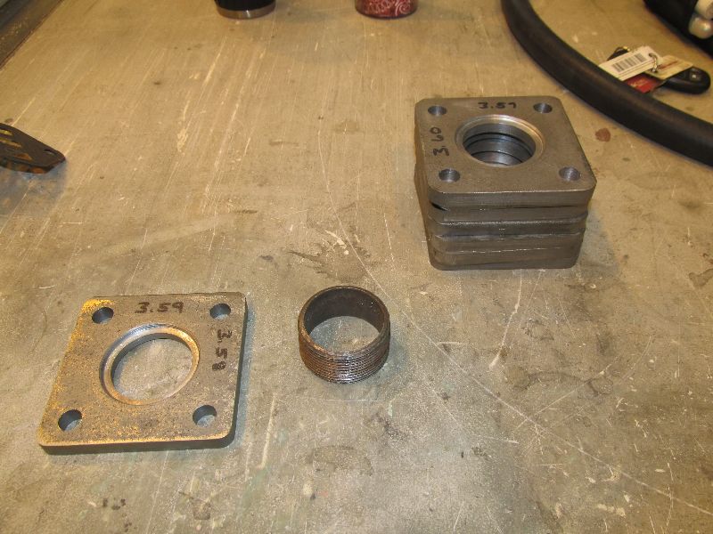
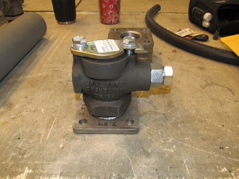
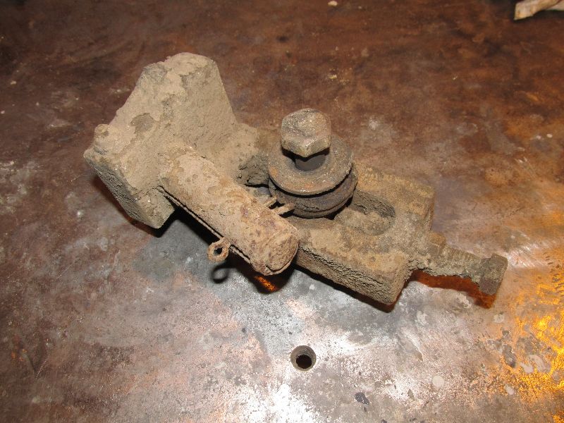
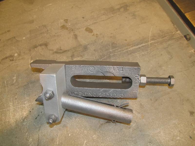
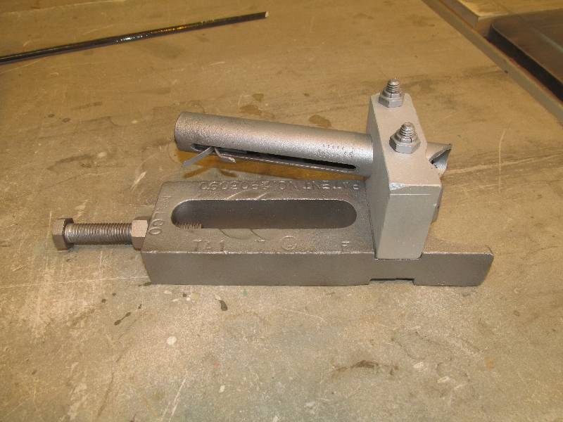
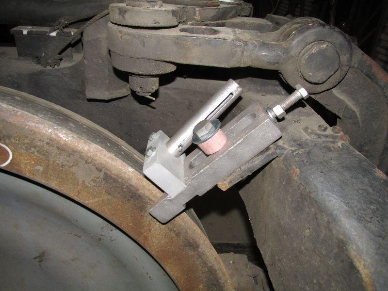
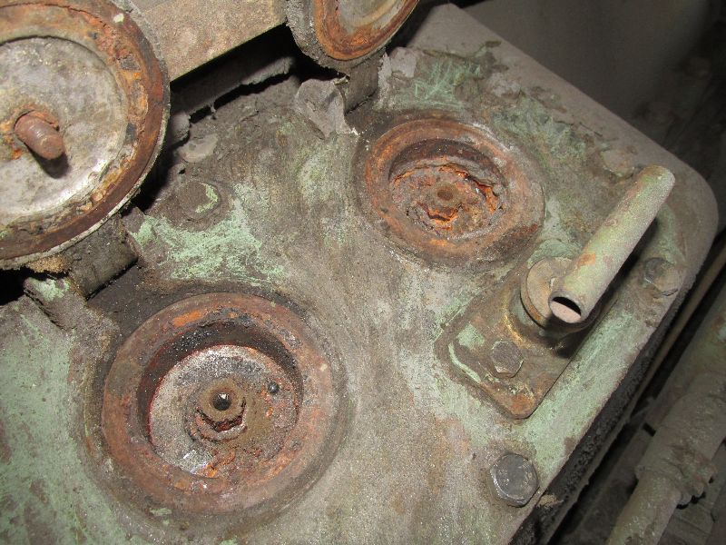
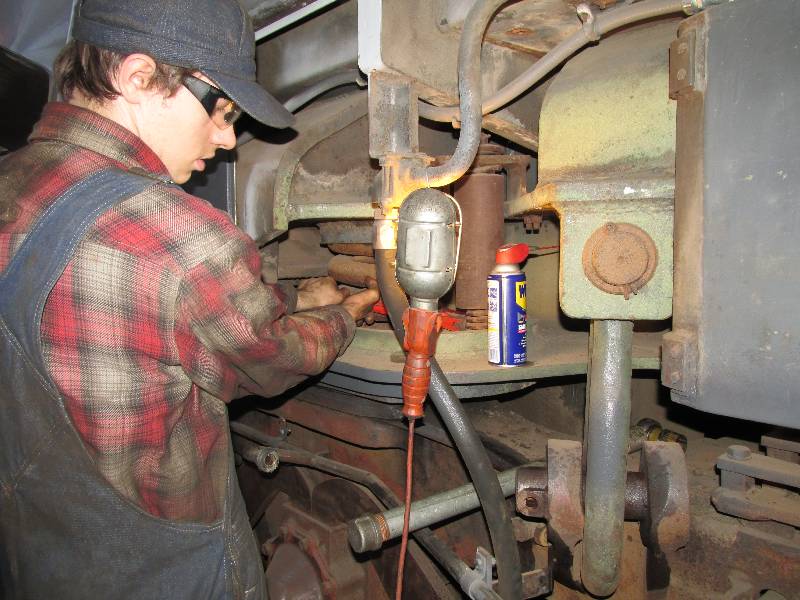
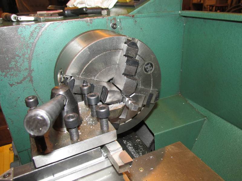
There are 8 sand boxes, each one having a shut off valve mounted to the bottom of the frame mounted sand bin. Each of the valves is supposed to have a sand trap mounted to its bottom but they were all removed during Camera Car conversion. Several of the shut off valves were in the shut off position and thus we decided to remove them all and clean them up and repair broken handles. Because of the way they are mounted, we built a "socket" that would grab the valve, allowing it to be unscrewed with a 3/4" breaker bar and socket. Remarkably, all eight of them were removed without too much effort.
 |
 |
 |
 |
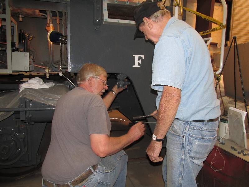
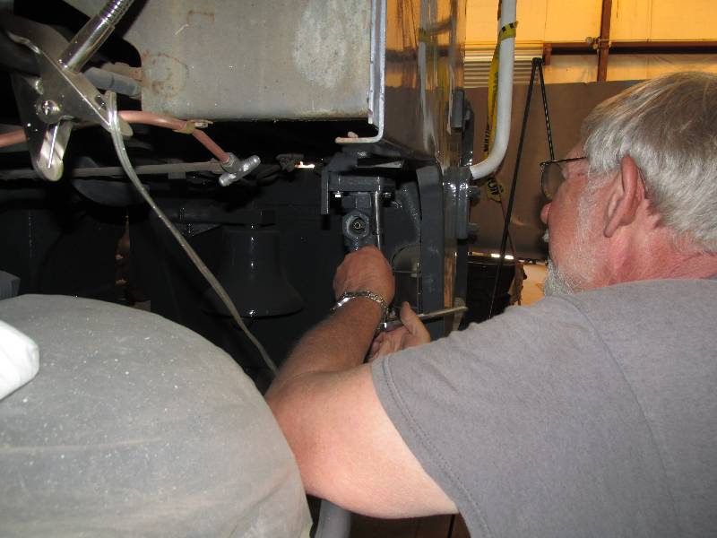
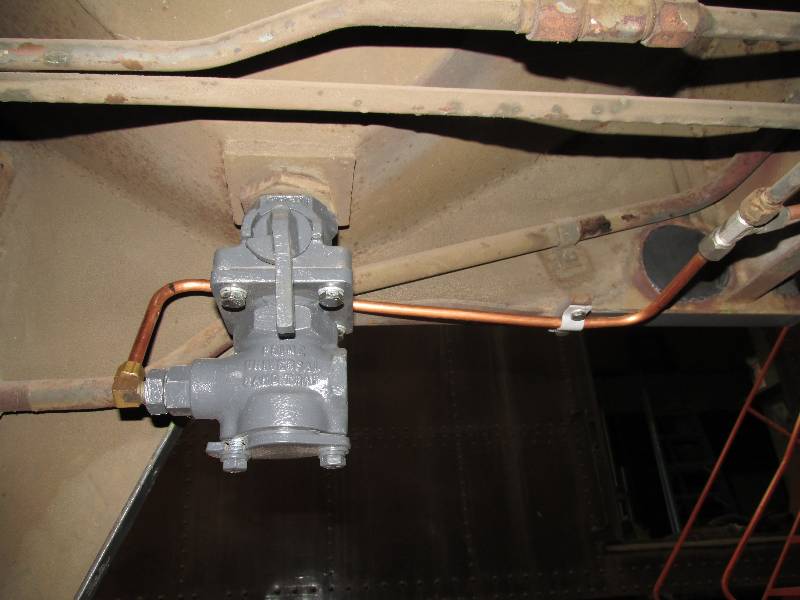
Once the shut off valves were all repaired, we attacked the issue of the missing sand traps. The sand trap is the device that feeds sand from the sand box to the sand pipes at the wheels. The SP had removed all of the sand traps but we discovered that a nearly exact replacement was available. Eight of them were purchased (at $145 each), new mounts made and they were put back where they belong. Bill and Rich are doing the honors in the last photos.
 |
 |
 |
 |
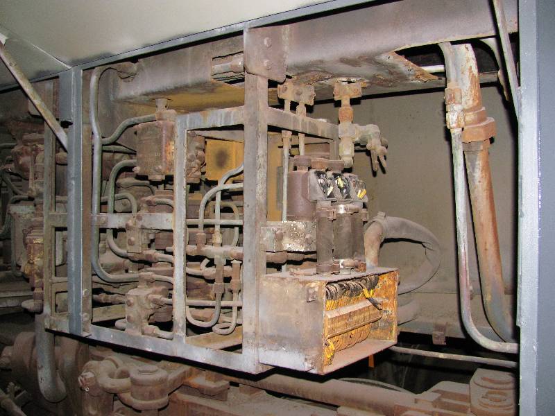
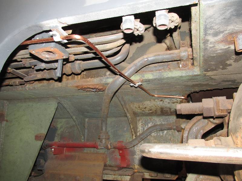
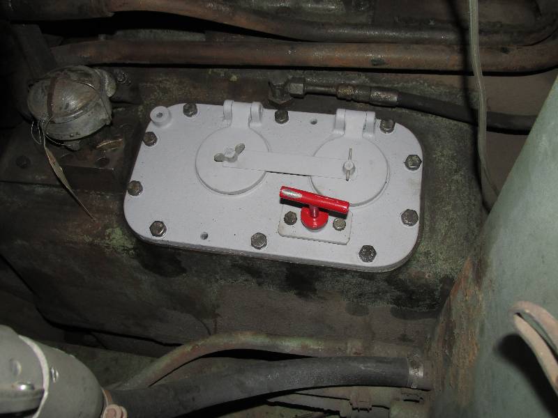
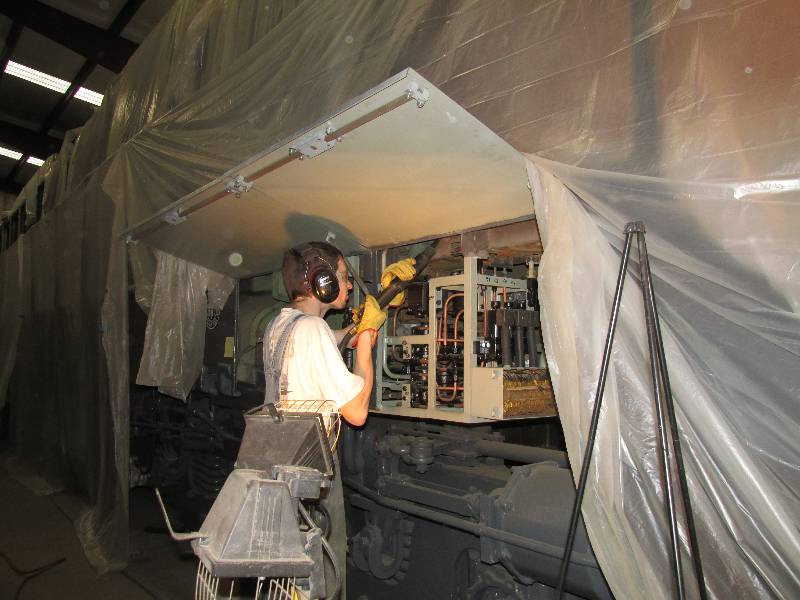
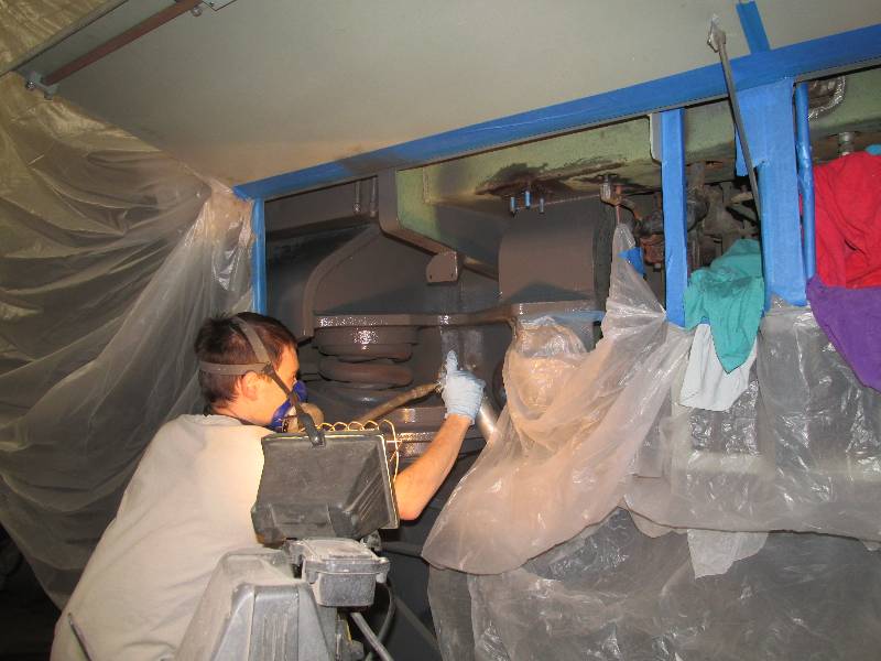
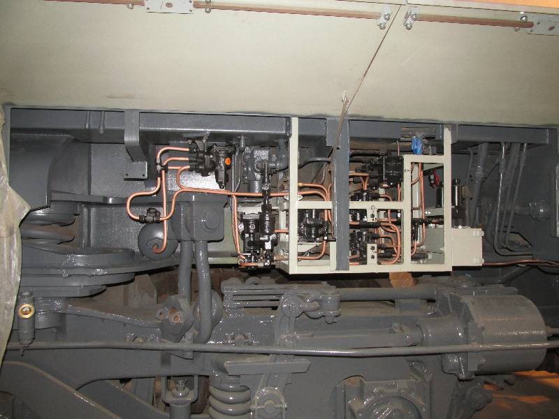
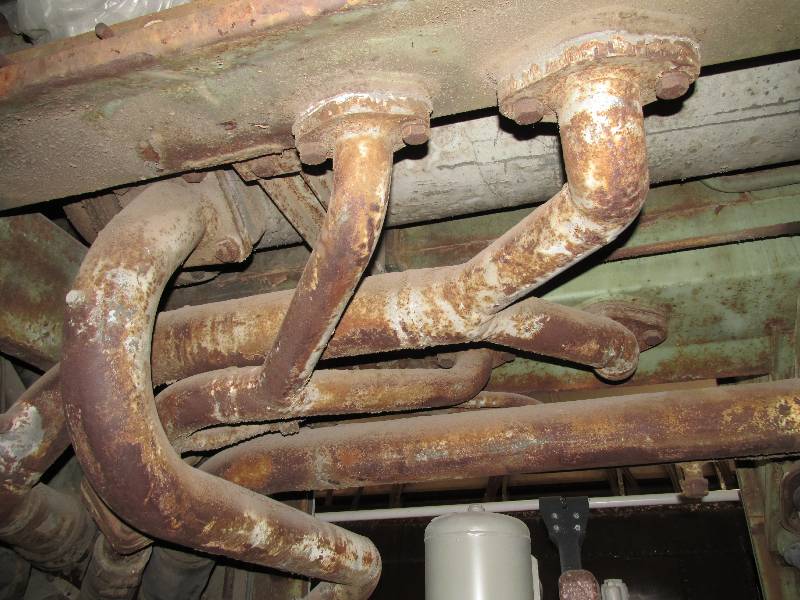
And while on the subject of the
sanders, the rather complex sanding control system needed a complete
rebuild. There are 3 solenoid valves that are operated by the
wheel slip circuitry. There are 2 double check valves that
are
operated either by the manual sanding valve in the cab or by the MU
sanding lines. And, there are 4 sanding relay valves that are
operated from either the solenoid valves or the double check valves,
Every single valve was full of dirt and completely
inoperative. Not only that but most of the copper lines were
plugged with wasp nests. It certainly was a mess.
 |
 |
 |
 |
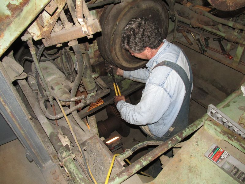
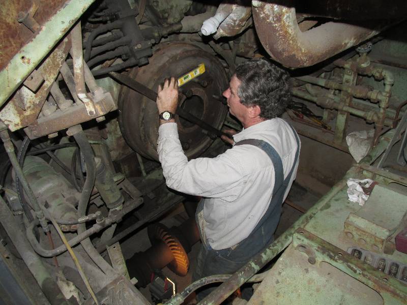
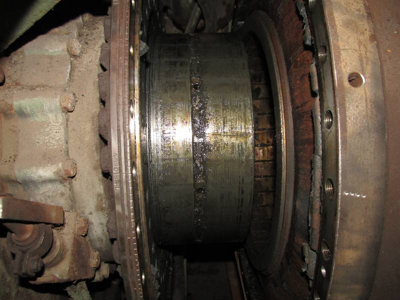
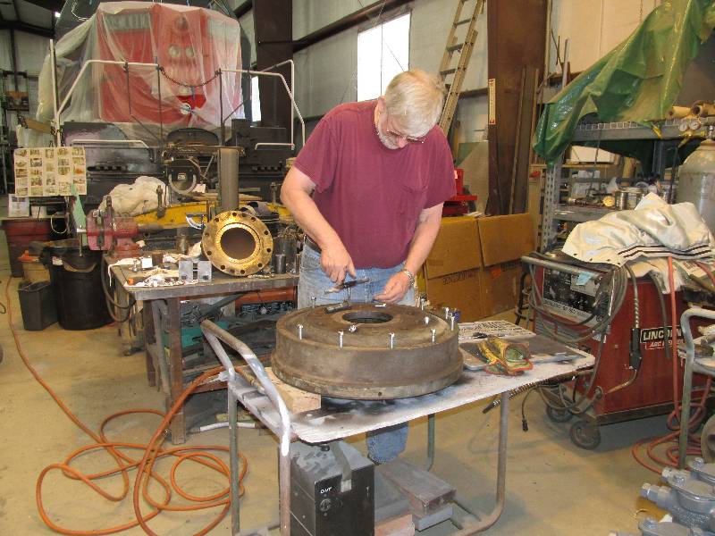
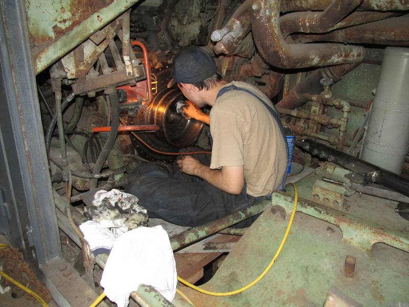
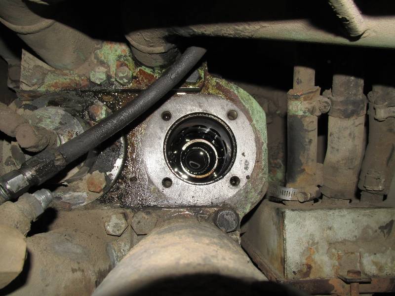
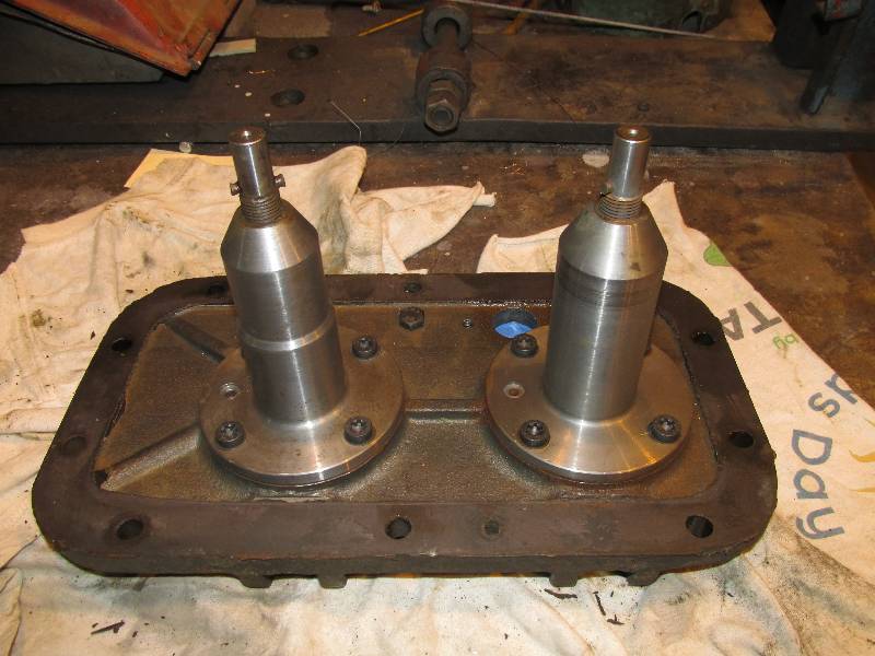
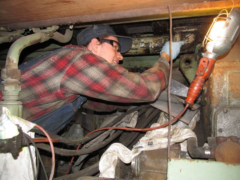
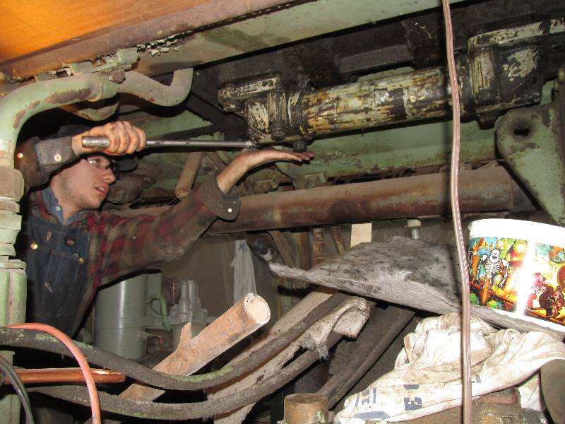
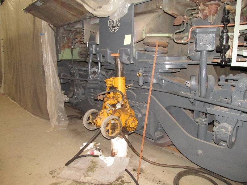
Dennis has taken on the chore of removing the resilient coupling from the engine crankshaft rear end. This has to be done because the rubber portion of the coupling is extremely worn and cracked. We cannot afford to install a new output Cardan shaft to this coupling in its current condition. One of our team members in Germany is investigating the purchase of a new rubber portion but we need to get the coupling apart in order to verify some dimensions and check condition of the internal bearing. There are 32 bolts that secure the outer coupling ring to the "timing plate" which is driven by the engine. Dennis had to bar the engine over a bit at a time so we could reach those bolts and remove them.
 |
 |
 |
 |
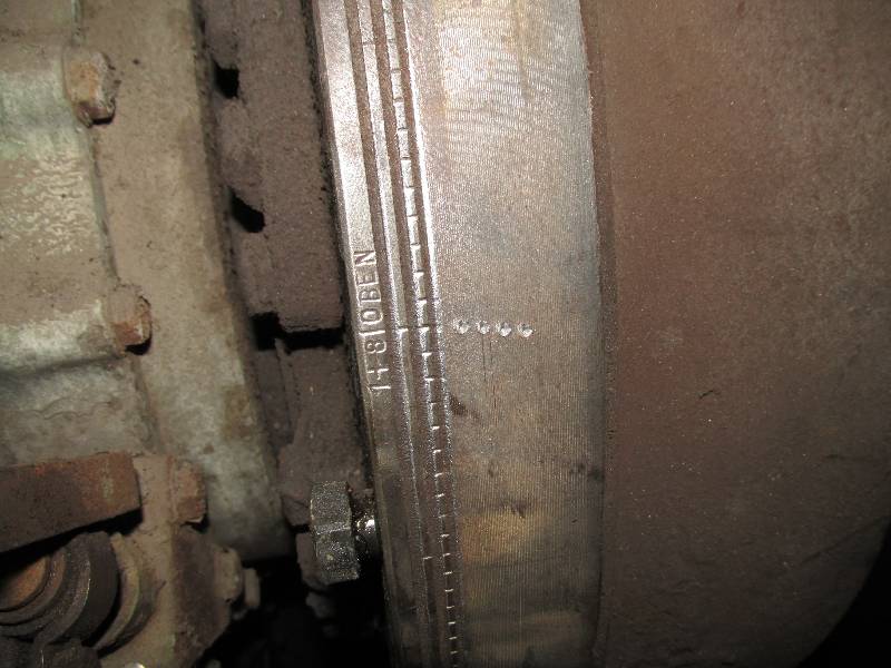
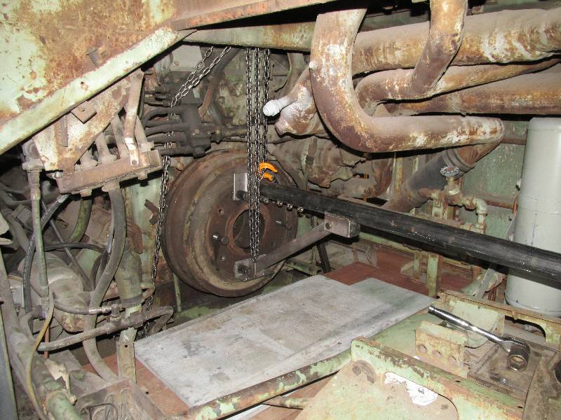
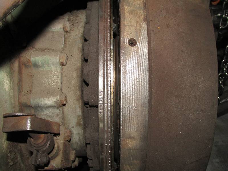
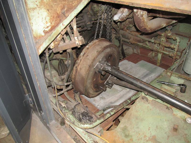
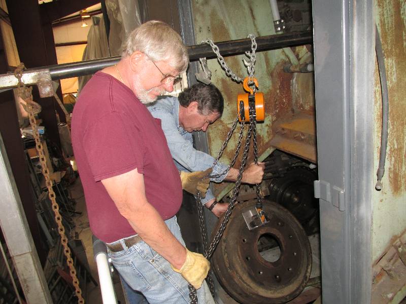
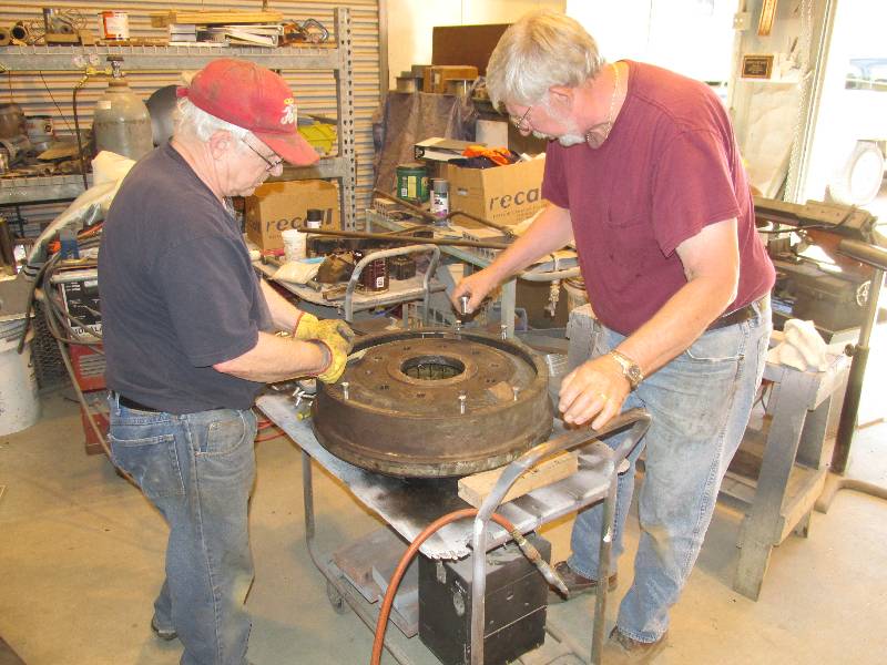
Once the timing plate bolts were all out, Dennis positioned the crankshaft so that one pair of coupling bolts were horizontal at the top. This was done so we could attach a custom made coupling tool to the coupling. At this time, we also marked the relationship between the timing ring and the coupling. A chain hoist was rigged to the radiator frame and attached to the coupling tool. With a little encouragement from Bill on the chain hoist, Dennis with a small pry bar and me on the coupling tool, the coupling was soon off and moved to our work area.
 |
 |
 |
 |
 |
 |
 |
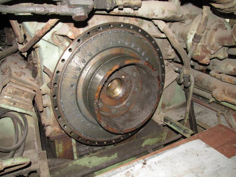 |
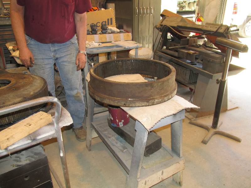
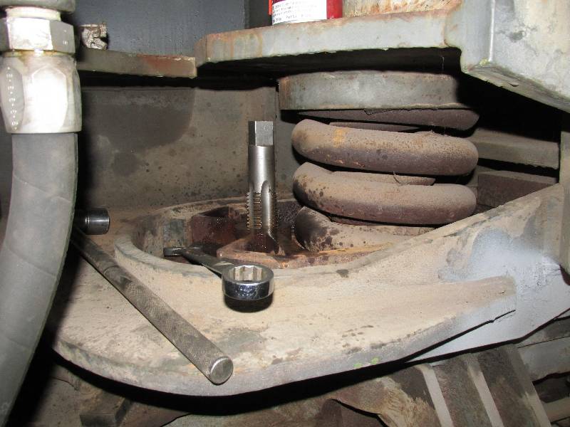
After Bill cleaned out the jacking
bolt holes with a 10mm tap, we began the process of removing the outer
ring from the rubber section. It went very smoothly
and
soon we had 2 pieces where there had been one.
 |
 |
 |
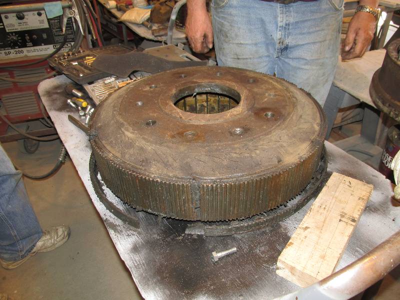 |
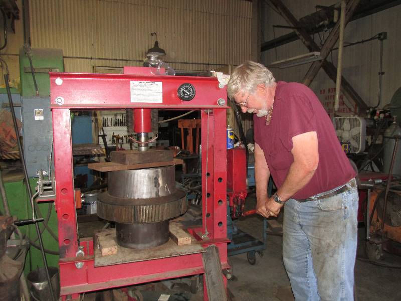
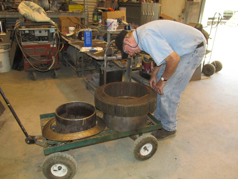
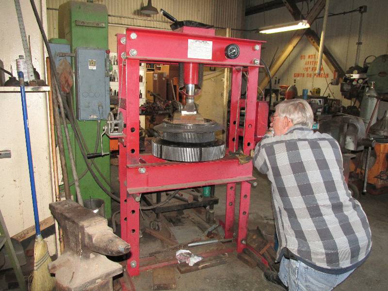
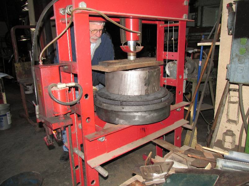
We then cut 2 pieces of 1/4" wall pipe and by cutting sections out of the wall, we made two rings. One will be used to push on the inner teeth of the rubber part and the other to support the bolt face of the coupling. With the help of our 50 ton hydraulic press, the two pieces were eventually separated from each other. Interestingly, the rubber ring refused to budge until the hydraulic pressure reached the presses limit of 50 tons and then it came loose with a very satisfying "bang". Rich is seen examining the molded in data plate on the inside surface of the rubber. This plate tells us the density of the rubber and allows us to begin the process of getting a replacement rubber ring. While most of us were engaged in the disassembly of the coupling, CJ was hard at work cleaning the pieces of the coupling that remained attached to the engine crankshaft. Once everything was clean, he applied a coat of preservative oil and tied a plastic bag around everything.
 |
 |
 |
 |
 |
 |
 |
 |
Dick has removed all eight of the original flange lubricators from the existing trucks. They use a graphite stick which rubs against the inside edge of the wheel flange, decreasing flange wear. They were removed from the French trucks so four will go onto the new rear truck and four will go back on our existing front truck.
 |
 |
 |
 |
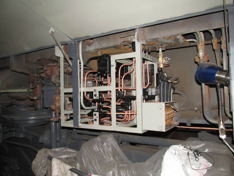
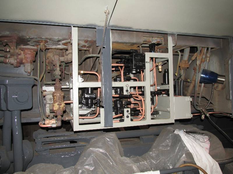
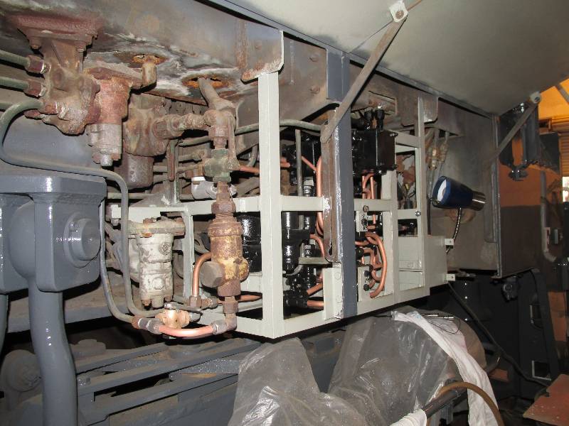
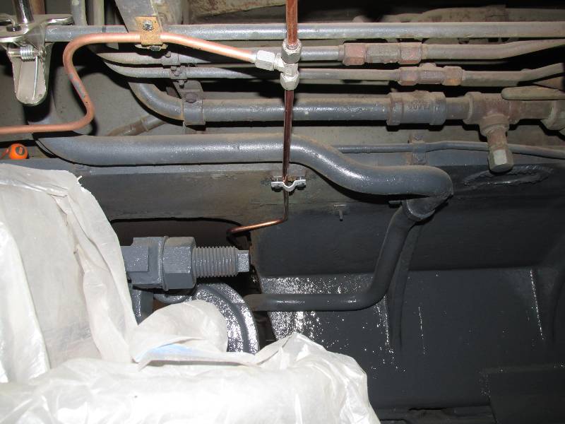
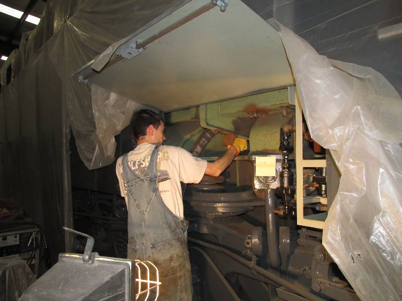
Work has continued on the sanders.
Much
of the copper piping was stolen so new bits are being formed and put
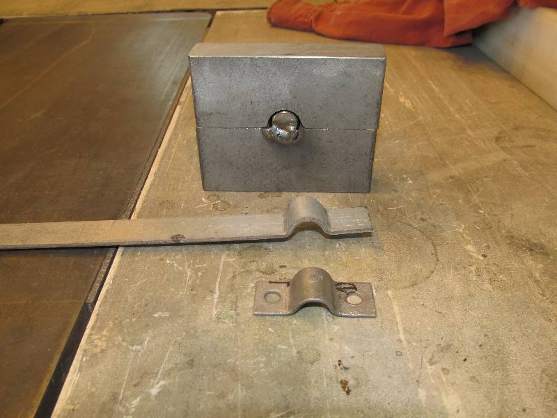
into place. One interesting thing we had to do was make about
a
dozen of the small tubing clamps seen in the first photos.
The
originals had been thrown away by the copper thieves and they are not
an 'off the shelf' item. So, we made a die that could be
pressed
with our hydraulic press to create new clamps. It worked
rather
well or as they say, 'crude but effective'.
 |
 |
 |
 |
-- Update December 06, 2014 --
The transmission in the 9010 has received a bit of past attention but is mostly an unknown. We do know that it was serviceable when the locomotive was put out of service in 1968 but that is about it. Sometime in the past, it was drained of its fluid but whether that was during the camera car conversion or when at CSRM in Sacramento, we don't know. It appears to be complete, except of course for the Cardan shafts connecting it to the Maybach engine and the rear truck. Until November of 2014, it was also missing all of the wiring connecting it to the control systems in the cab.
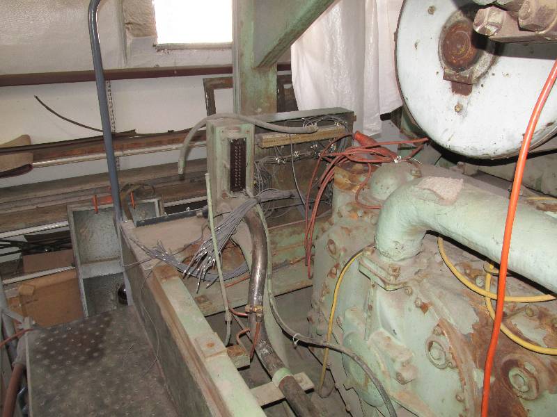
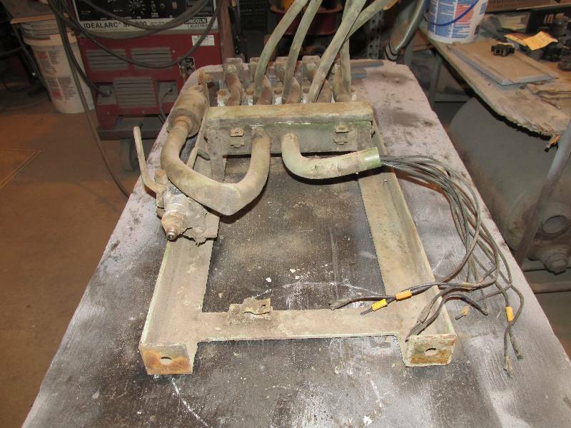
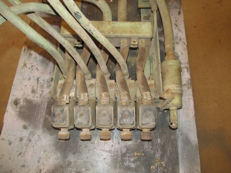
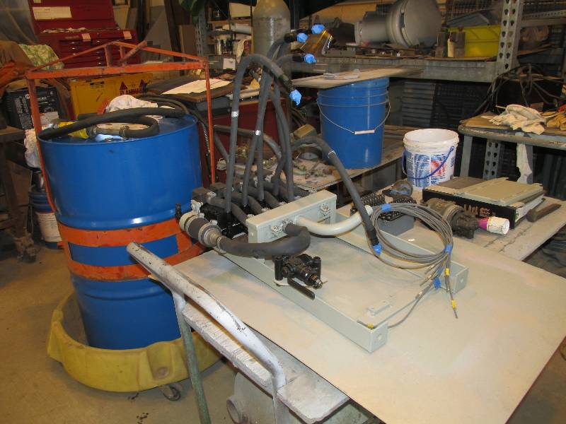
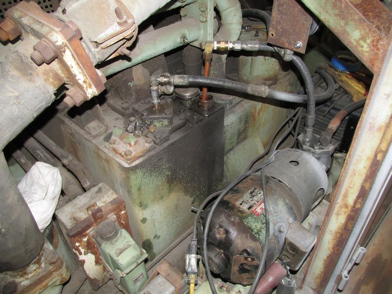
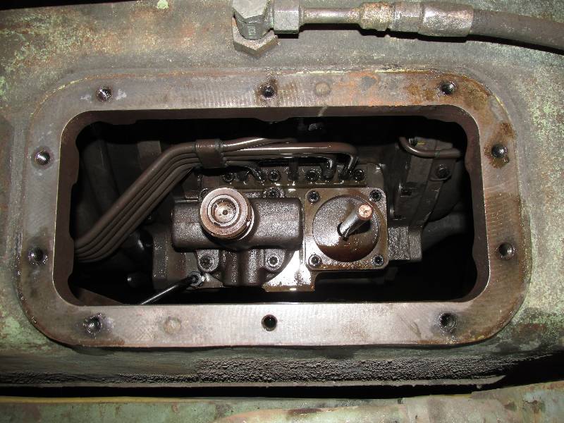
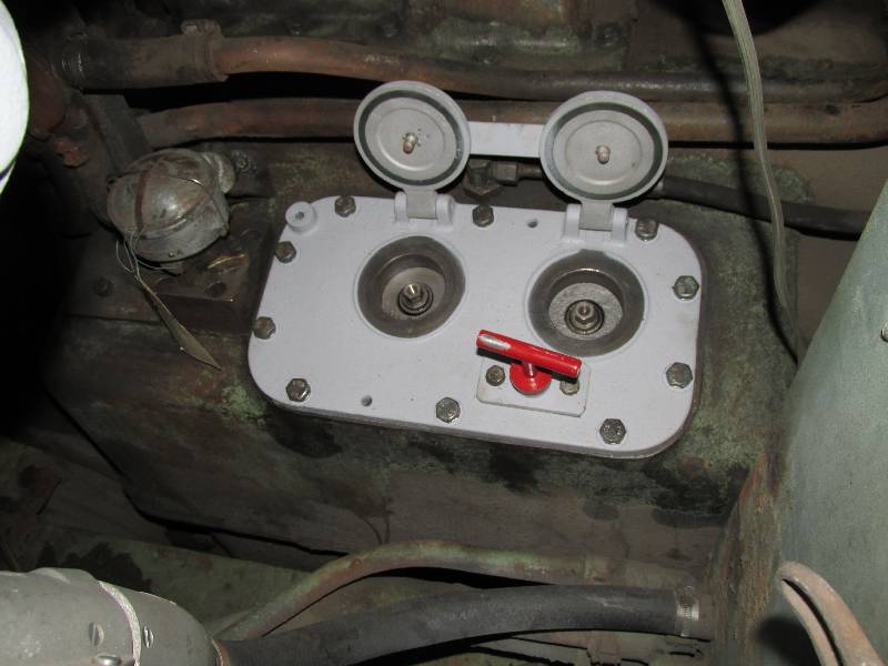
Some time ago, the small rack containing the control valves for the hydro-dynamic brake was removed in order to get access to the rear main terminal board for wiring. It was completely cleaned, rebuilt and tested.
 |
 |
 |
 |
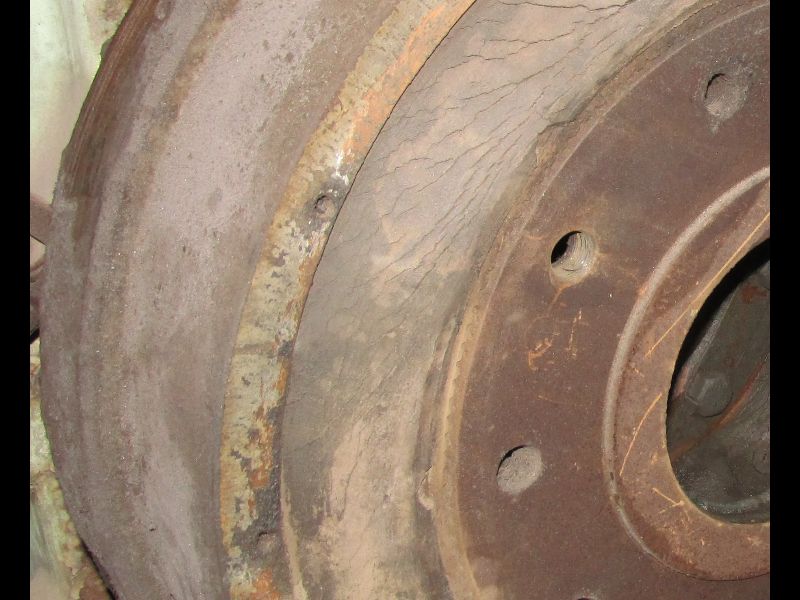
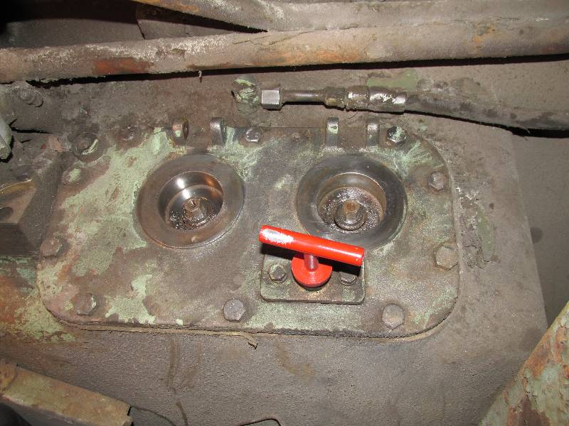
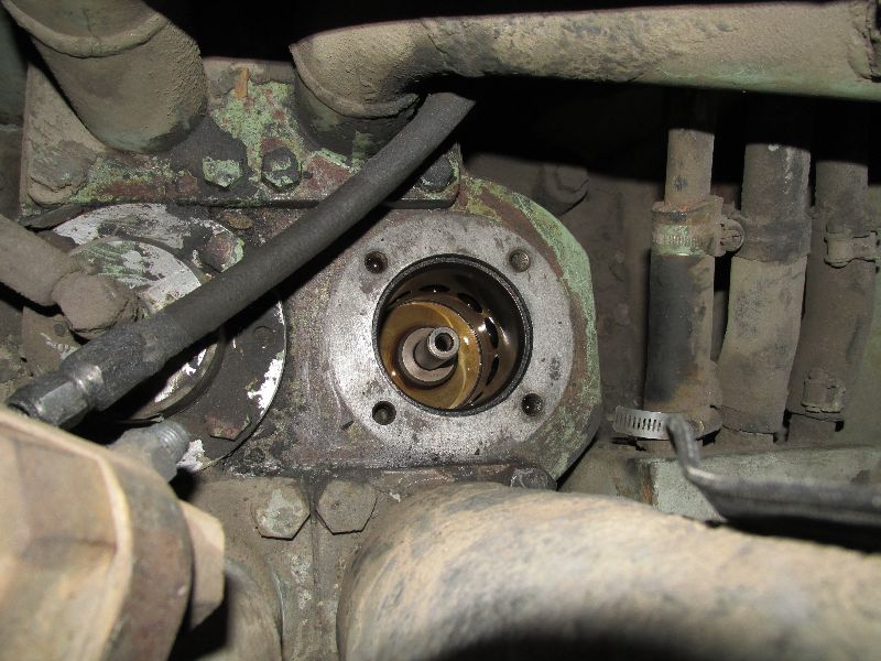
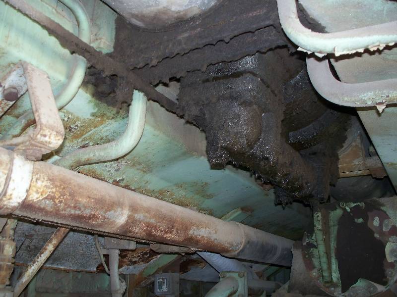
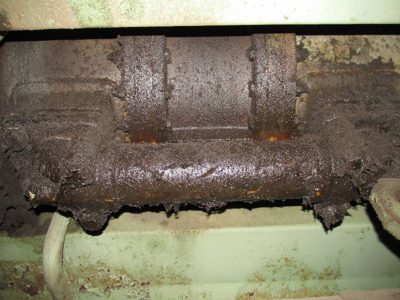
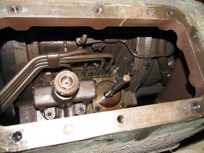
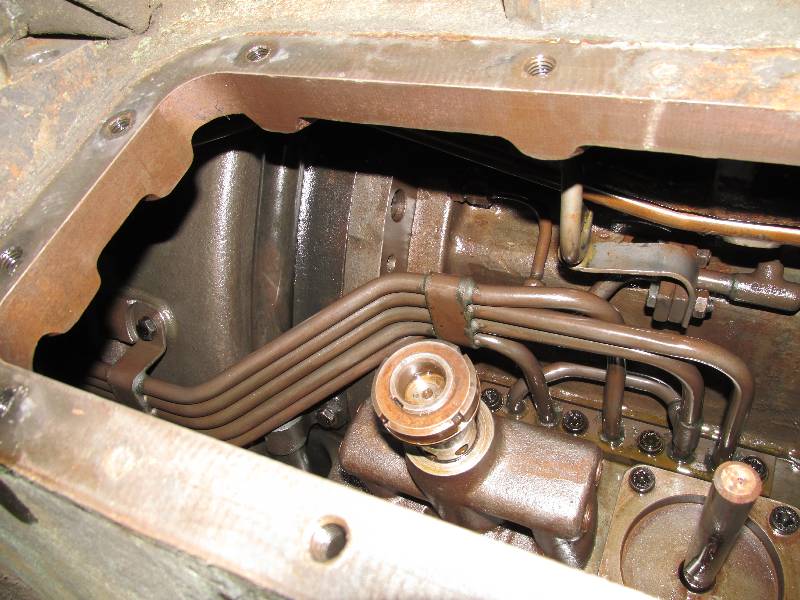
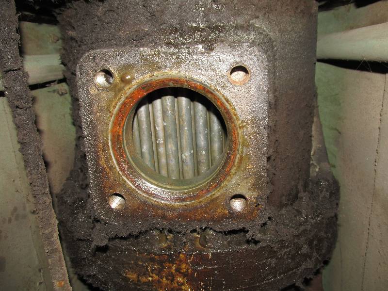
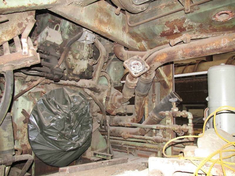
While examining the transmission, I opened the covers that protect the converter control rods and discovered this mess. They are not normally exposed to the weather but when the radiator elements were stolen, there was nothing keeping rain water away from the transmission and this is what happened. I also pulled the dip stick and saw that it was severely rusted. Further examination revealed that there is no rust inside the transmission case and no explanation of the rusted dip stick. The control rods and housings were cleaned as was the dip stick and all seems to be well in that department.
 |
 |
 |
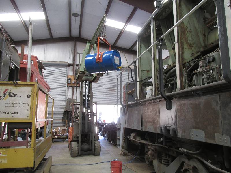
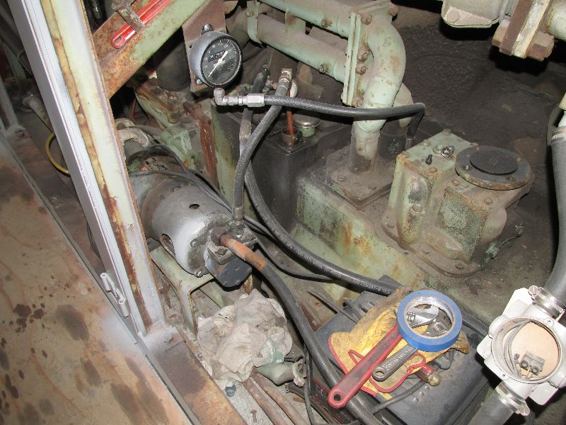
We decided that because of the
impending purchase of the Cardan shafts and completion of the control
wiring, we would see if the transmission is operational. This
started by purchasing 2 barrels of transmission fluid. The
transmission holds 200 gallons but because of it cost, we bought only
110 gallons for now. Bill and I connected a welder to the
dynastarter and spun the transmission as fast as the welder could turn
it, which turned out to be 475 RPM, somewhat shy of the engine idling
speed of 680 RPM. A gauge was installed on the line between
the pump and the heat exchanger and after some time running, no
pressure was observed. We had a good look at what little
documentation we have and removed the cover from the "duplex non-return
valve" and found it to be stuck, a condition which would prevent the
fluid from circulating. The piston and walls of the valve
bore were coated with varnish, probably from sitting for 40+ years.
The valve and bore were cleaned and re-assembled.
Thanks go to our friend Simon with the DEPG in the UK who been of great help to us with Voith transmission information.
Thanks go to our friend Simon with the DEPG in the UK who been of great help to us with Voith transmission information.
 |
 |
 |
 |
There has been concern
that with no
fluid pressure, we were not lubricating the bearings and other surfaces
inside the transmission. I gathered some odds and ends and
rigged a pump that would pull oil out of the sump and put it into the
filter preceding the "lubricating line". Running
the
pump yielded about 4 pounds of pressure in the lubricating system.
 |
 |
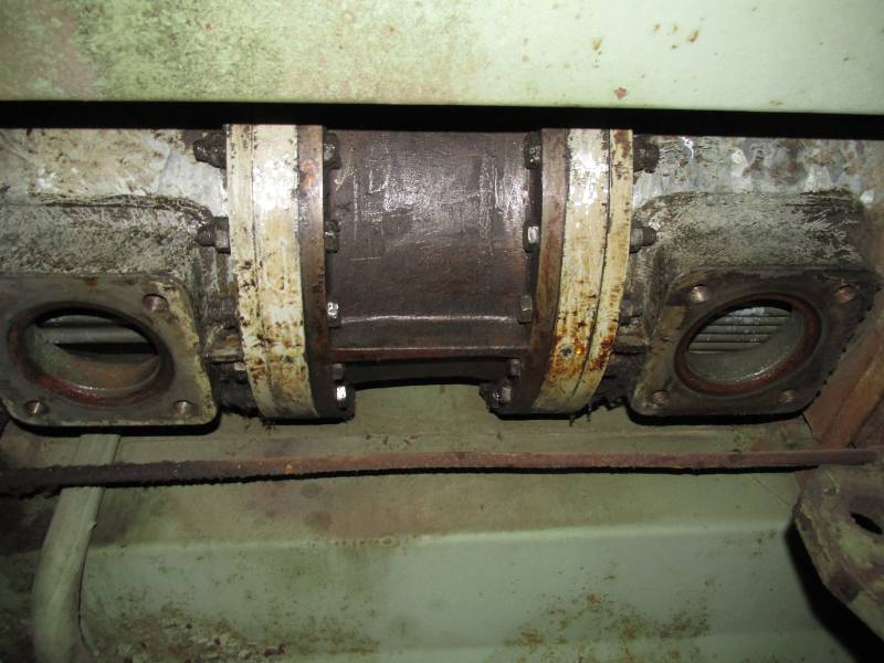
After installing the external
lubricating pump,
we decided to spin the dynastarter using the locomotives battery
supply. This yielded 540 RPM, still shy of the idling speed
but
the lubricating oil pressure came up to around 8 pounds. At
this
point, we realized why the heat exchanger is so oily in its
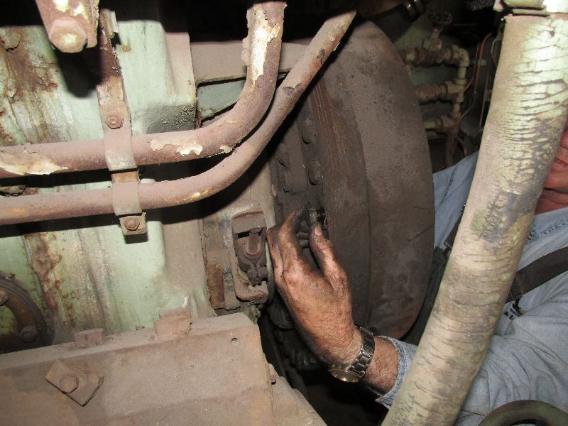
center section - it leaks. This will have to be addressed
before
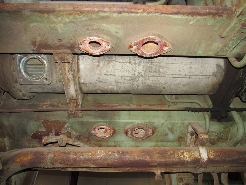
we get very serious about running the transmission. The heat
exchanger is made in two sections with the pipe you see connecting the
water flow between them. The leak is coming from one (or
both) of the bolted
flanges above the pipe.
 |
 |
This
is a continuation of the mess noted in the December 06 update.
After studying our literature and determining that things
might not explode, I removed the cover from the control
valve section of the transmission. Sure enough, nothing
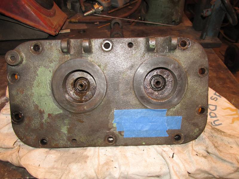
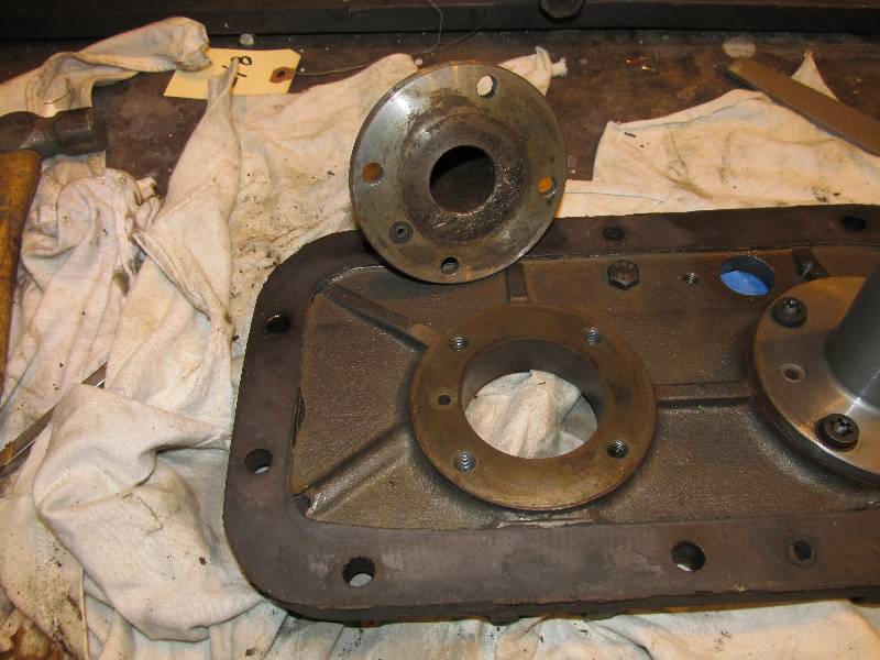
exploded. :-) First, we have top and bottom views
of the cover, with the two manual actuating rods attached.
Next is a view of one of the actuating rod assemblies followed by a view of what I found when I took the assemblies apart. The rods had sustained some damage to their threads from the rust but nothing that will keep them from screwing in and out of the housing. Much cleaning followed by a bead blasting made them look good again and removed the possible contamination from the rust. They were re-assembled, lubricated and re-installed on the cover.
The 3 views inside the transmission case show that it is very clean and oily. You can see the two control valves clearly. To the right of the valves is the #3 converter housing and to their left is the #1 converter housing. The #2 converter housing is out of view to the right.
The last photo tells a story. The prototype locomotives had a "part fill" function that occurred when the throttle was put in position 1. In the first photo, note at the upper left of the cover, there is a extrusion on the cover and a plug in its hole. This was the connection point for the air line that controlled the "part fill" function. The last photo is of the cover, turned over so that extrusion is at the lower left. You can see a small hole in the rim where the rod housing bolts and a corresponding hole in the flange of the rod housing. In fact, this hole appears in both housings although there is no hole in the cover piece for the right hand control rod housing. Now, refer to the 4th photo and you will see the same hole in the bottom of the rod housing. The hole connects to - - nothing. Whatever connected the rod housing to the left hand control valve is not there and I can see no sign of anything plugged or blanked off at the control valve. This is an interesting vestige of the transmission's use in the prototype locomotives.
 |
 |
 |
 |
 |
 |
 |
 |
Eventually, the cover was
re-installed on the
transmission. It certainly looks much better than it did a
couple
of weeks ago. On another front, CJ is home from college and
has
taken on the task of cleaning and removing the water connection pipe
mentioned in the last update. We need to get it out of the
way so
we can determine the source of the heat exchanger oil leak.
CJ had it cleaned and removed in just a few hours so we were
able to take a look inside the exchanger. It looks
beautifully clean which is a testament to the Southern Pacific's water
treatment program.
 |
 |
 |
 |
 |
 |
--
Update February 7, 2015 --
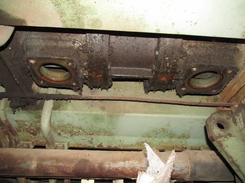
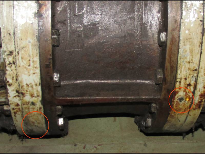
When CJ finished cleaning the center section of the heat exchanger, we found that the oil is coming from two small holes, one in each end of the center section. Conferring with our friend Simon in the UK revealed that these are "weep" holes put there to indicate that the converter tube sheet "O" rings are leaking. This is a problem that will have to be addressed at a later date because removing the converter will require removing the #2 cooling hood section.
When CJ finished cleaning the center section of the heat exchanger, we found that the oil is coming from two small holes, one in each end of the center section. Conferring with our friend Simon in the UK revealed that these are "weep" holes put there to indicate that the converter tube sheet "O" rings are leaking. This is a problem that will have to be addressed at a later date because removing the converter will require removing the #2 cooling hood section.
 |
 |
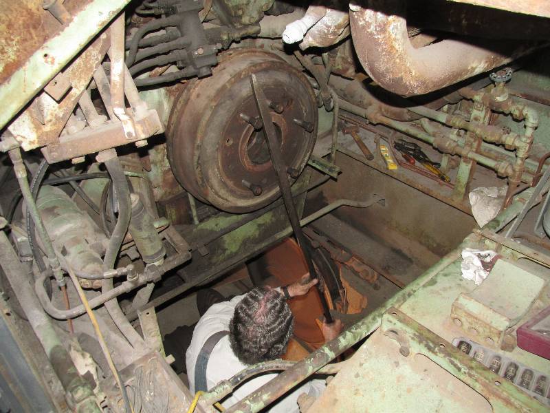
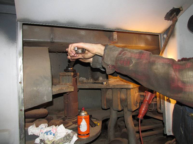
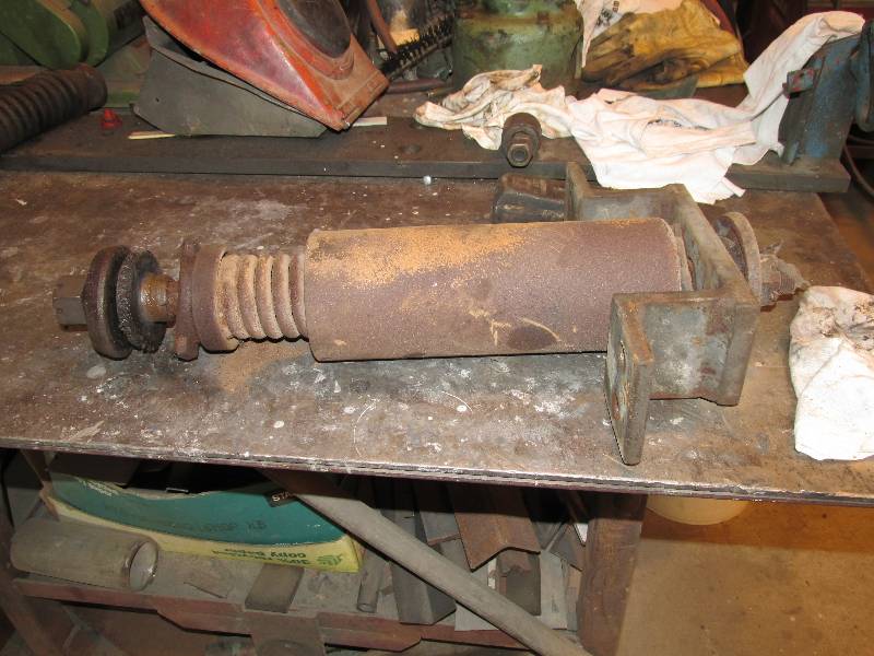
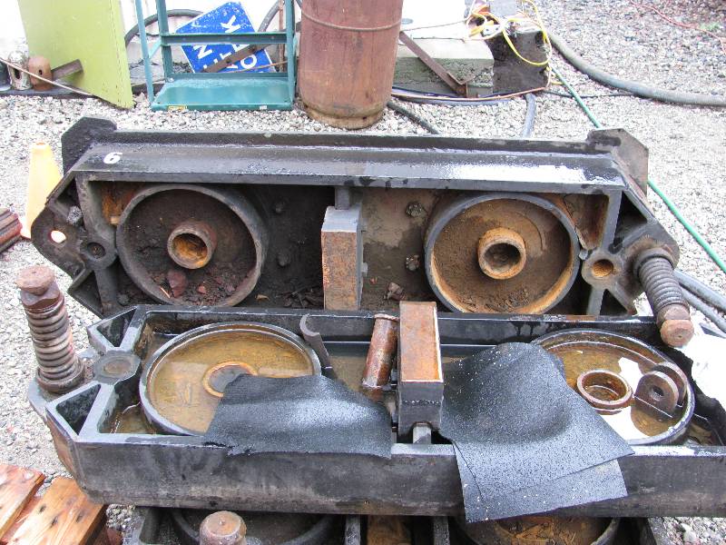
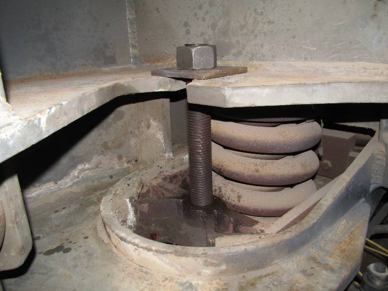
With CJ ready, willing and able,
we decided to examine the sliding plates (side bearings) as two of them
were found to have water in their lubrication wells. This
required that we first remove all 8 shock absorbers, a job that CJ
completed in a couple of days. Considering that they had been
in place for probably 50 years, it was a wonder that he did it that
quickly. We soon discovered that they are not actually "shock
absorbers" but rather "friction dampers" as they are not automotive
type hydraulic devices but purely mechanical instead.
 |
 |
 |
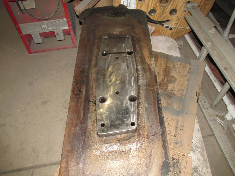
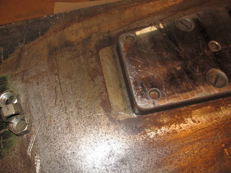
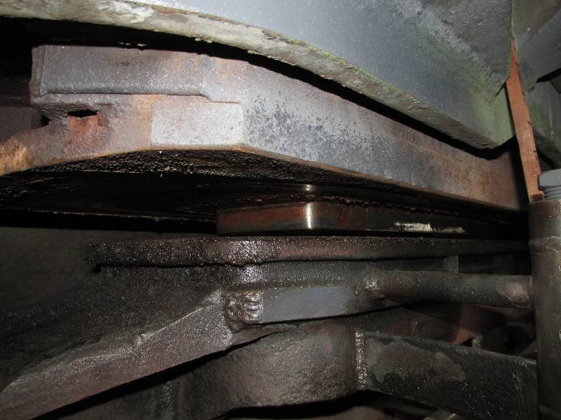
The sliding plates are bolted on the bottom of large carrier frames. While a bit dirty and somewhat wet, the frames we received with the trucks from France are in good condition and thought was given to replacing the frames currently in place on the 9010 as two of them are extremely rusty and corroded. Unfortunately, we discovered that the plates on the French trucks had been cut down in size to the point where they would not support the weight of the 9010. The shadow of the original plate size is visible on the underside of the carrier frame.
 |
 |
 |
 |
 |
 |
 |
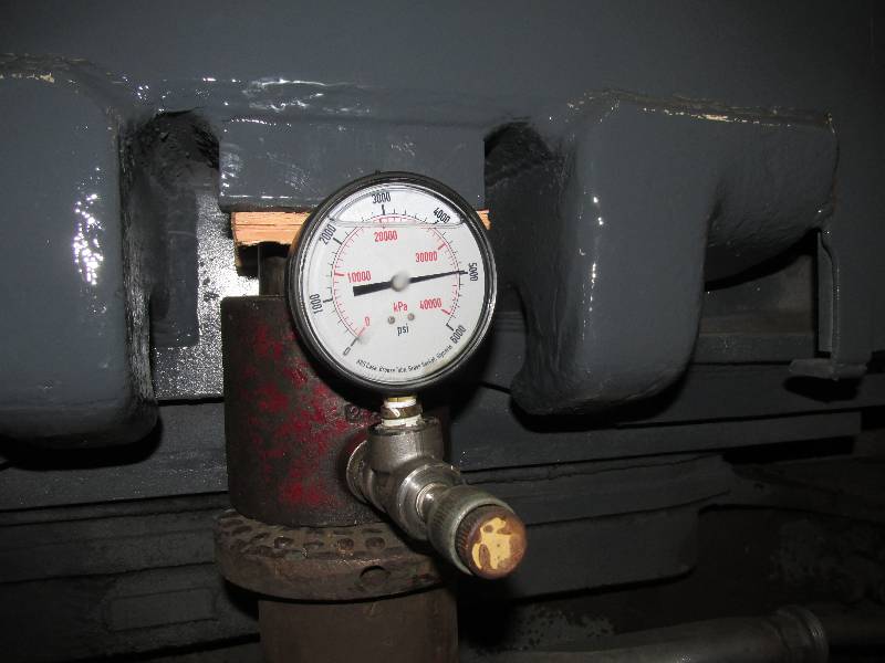
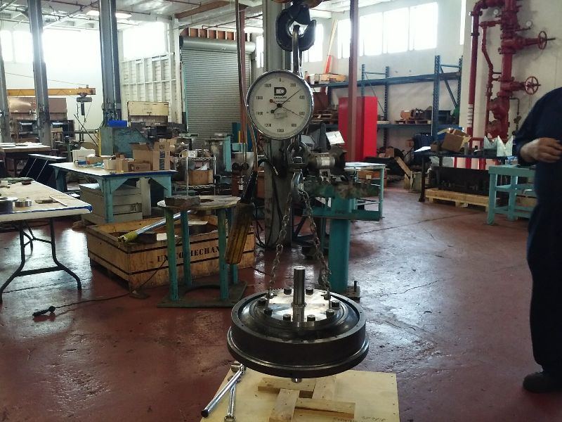
We used 4 jacks to raise the 9010.
With the sliding plate frames attached to the locomotive by
the threaded rods, we had to raise the 9010 about 3 inches in order to
see the bottom of the plates. While at it, I decided to weigh
the locomotive. This was done with a small 50 ton hydraulic
jack that we partially raised and put a suitable gauge on.
The
locomotive was raised evenly 4 times with the weighing jack
positioned once on each corner. In the photo, the gauge is
reading 4990 PSI which equates to 55089.06 pounds. Once we
had repeated the weighing process 3 times on each corner, we determined
that the 9010 weighs 101,678 at the front end and 108,192 at the rear
end. This information will come in handy when it is time to
rent cranes to lift the 9010 for the truck change.
 |
 |
 |
--
Update April 10, 2015 --
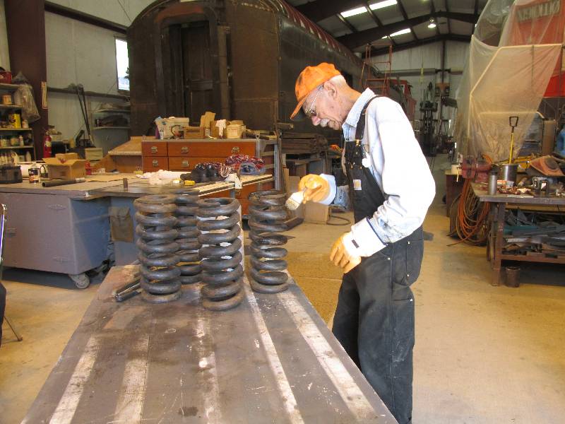
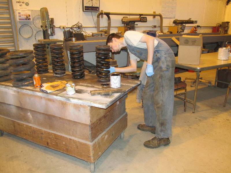
Dick has been cleaning and painting the main suspension springs we got from France. They are all in excellent condition and will be installed under the 9010 when we change the rear truck. My grandson Matthew also worked on a few of the springs during his recent visit.
Dick has been cleaning and painting the main suspension springs we got from France. They are all in excellent condition and will be installed under the 9010 when we change the rear truck. My grandson Matthew also worked on a few of the springs during his recent visit.
 |
 |
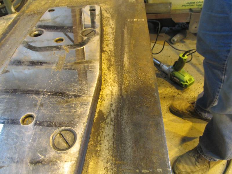
Matthew also completed a project
that I had started months ago. He finished the needle gunning
of the wheel slip and sanding control area of the frame.
After all the dirt and paint chips were cleaned
away, he fired up a small paint gun and turned the area dark lark gray.
It certainly is nice to have that project checked off the
list.
 |
 |
 |
 |
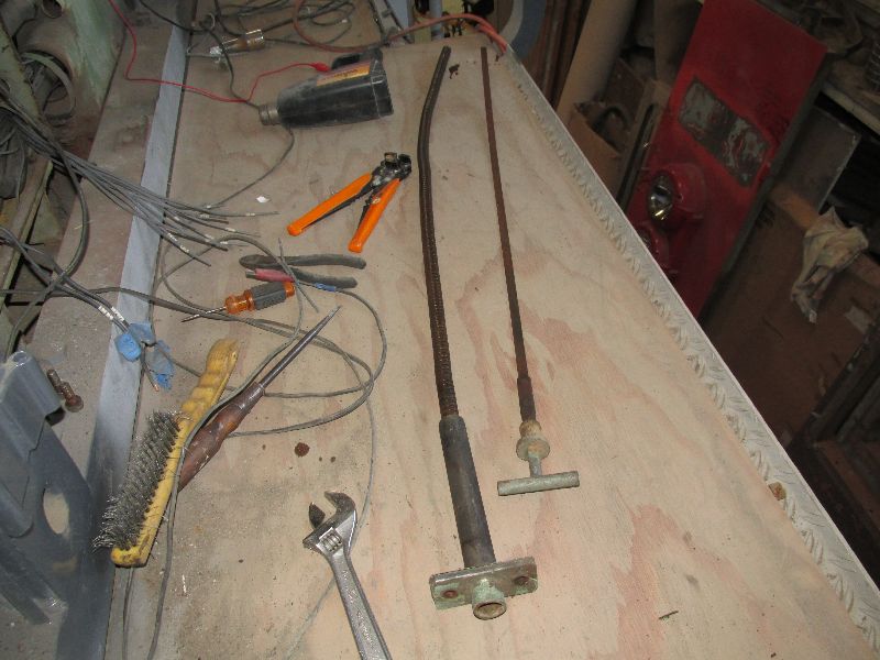
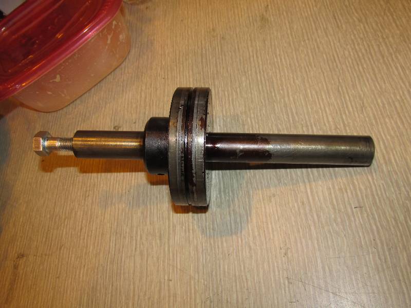
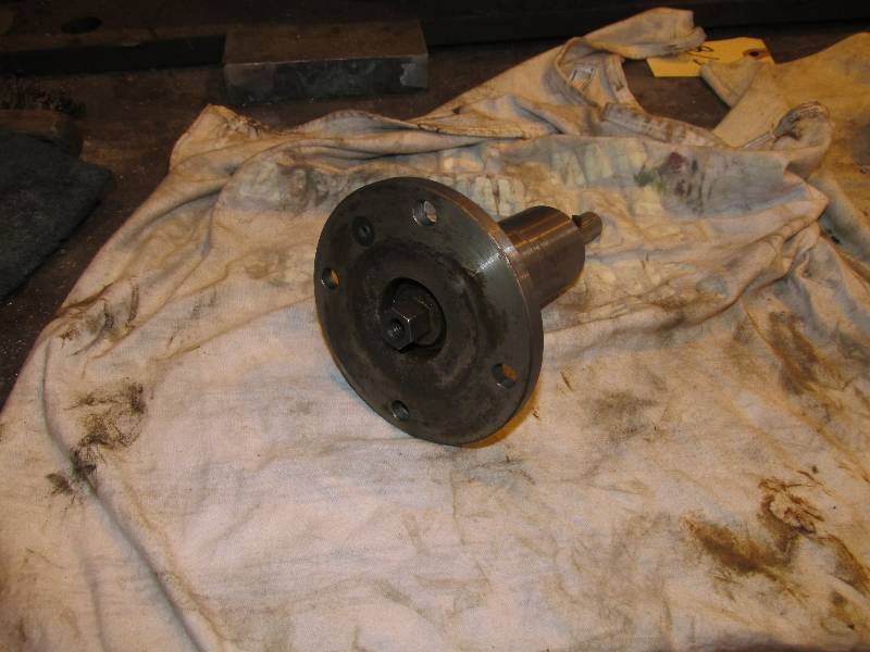
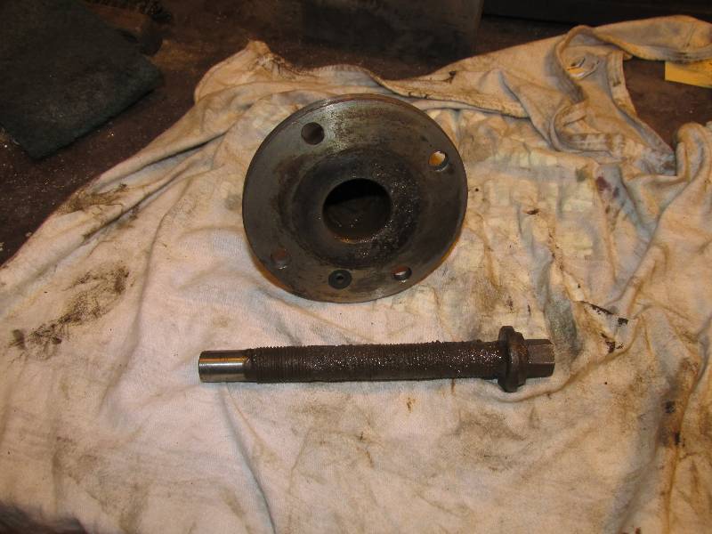
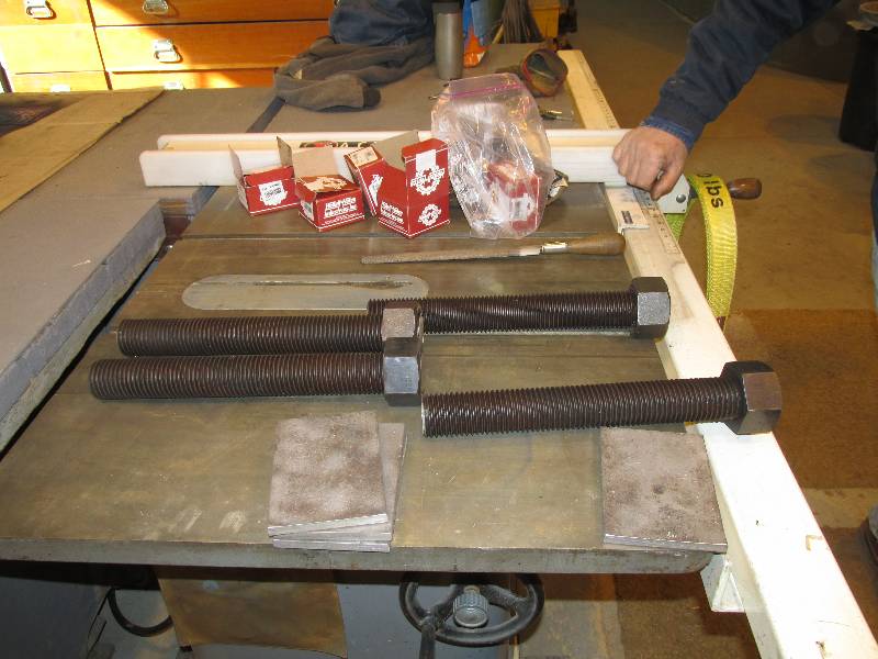
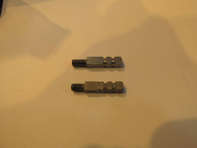
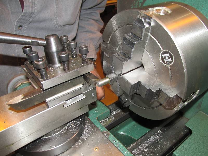
On another front, we are going to
have several dozen replacement door handles cast. The handles
have a molded-in steel shaft that goes through the latch and are held
in place with a nut. Bill had to make the shafts that will be
cast into the handles. In the first photo, the top shaft is a
"Bill".
 |
 |
 |
Meanwhile, I have been keeping
busy with a number of little projects like removing the water piping
from under the #2 cooling section. This is being done in
order to gain access to the transmission heat exchanger. When
the hood is removed, the exchanger has to come out to be repaired as it
is leaking oil, a situation described in the February 7 post.
 |
 |
 |
--
Update November 11, 2015 --
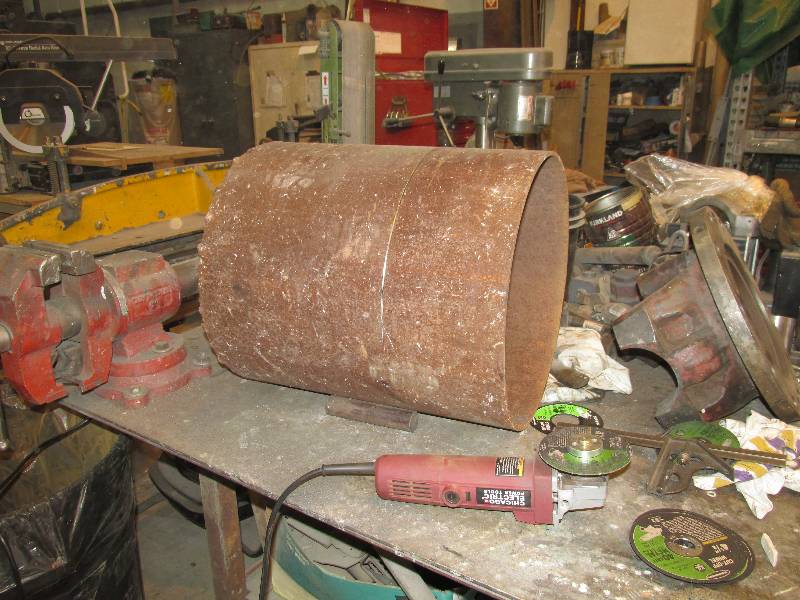
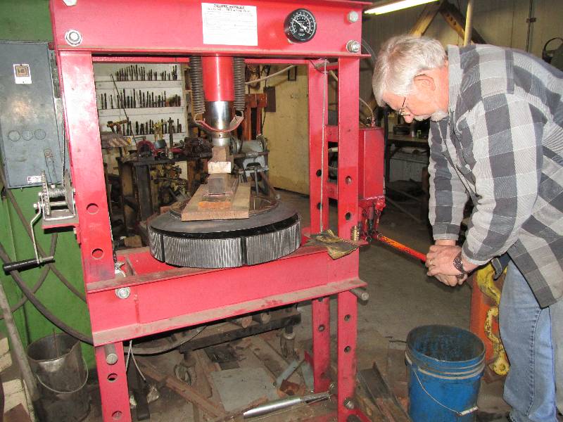
With reference to the July 16, 2014 update, the time was right to complete the rebuilding of the engine's resilient coupling. We purchased a new rubber part from MTU in Germany and it was shipped to us along with the new cardan shafts from the Welte Group. There was a sequence of operations which was prepared for us by team member Dirk. First, we had to press the central part of the coupling (the 'drum') into the new rubber piece. While disassembly required nearly 50 tons of pressure to break the two pieces apart, assembly needed only 22 tons . Clean parts and the proper lubricant made all the difference in the world.
With reference to the July 16, 2014 update, the time was right to complete the rebuilding of the engine's resilient coupling. We purchased a new rubber part from MTU in Germany and it was shipped to us along with the new cardan shafts from the Welte Group. There was a sequence of operations which was prepared for us by team member Dirk. First, we had to press the central part of the coupling (the 'drum') into the new rubber piece. While disassembly required nearly 50 tons of pressure to break the two pieces apart, assembly needed only 22 tons . Clean parts and the proper lubricant made all the difference in the world.
 |
 |
 |
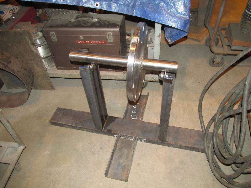
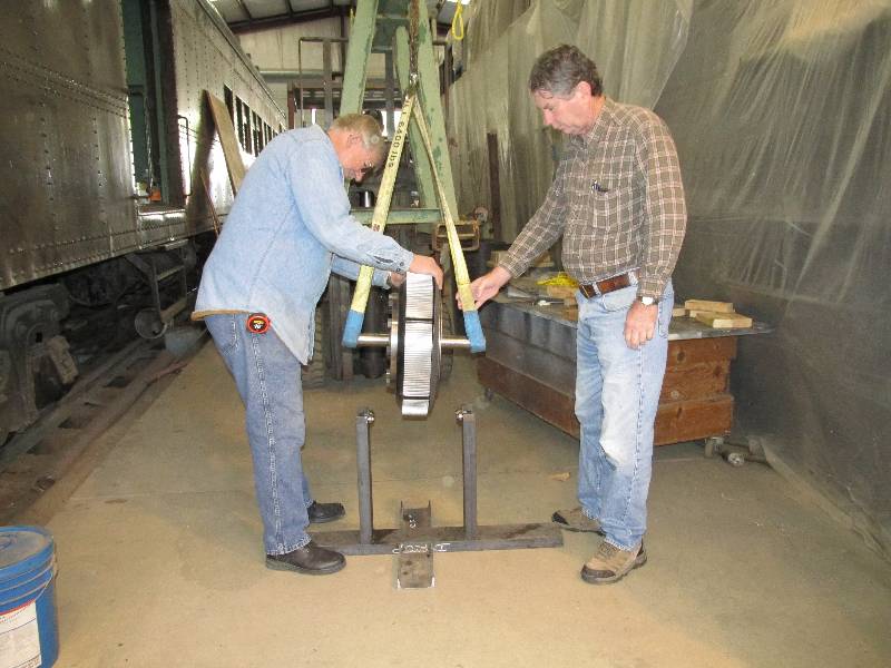
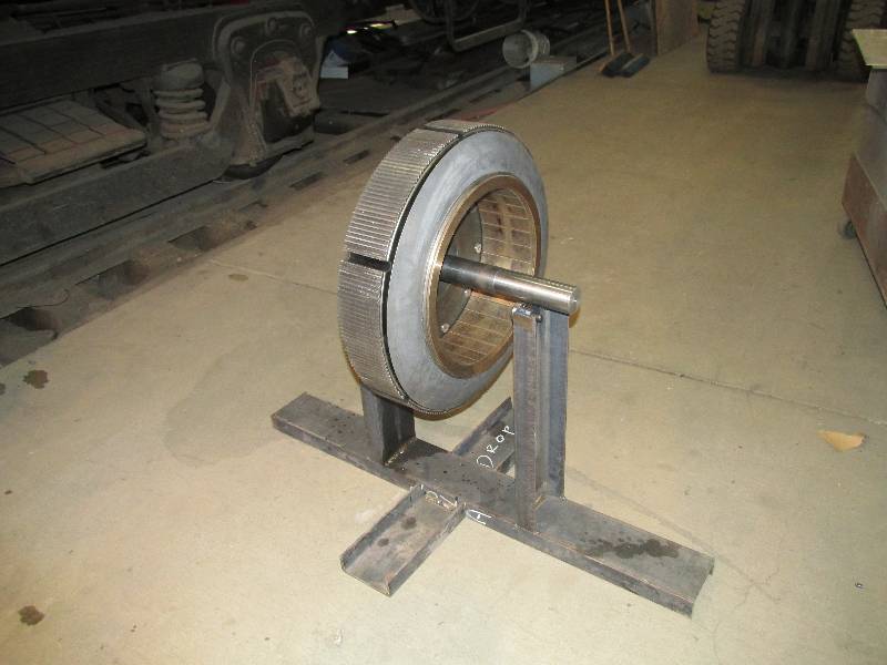
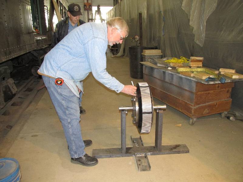
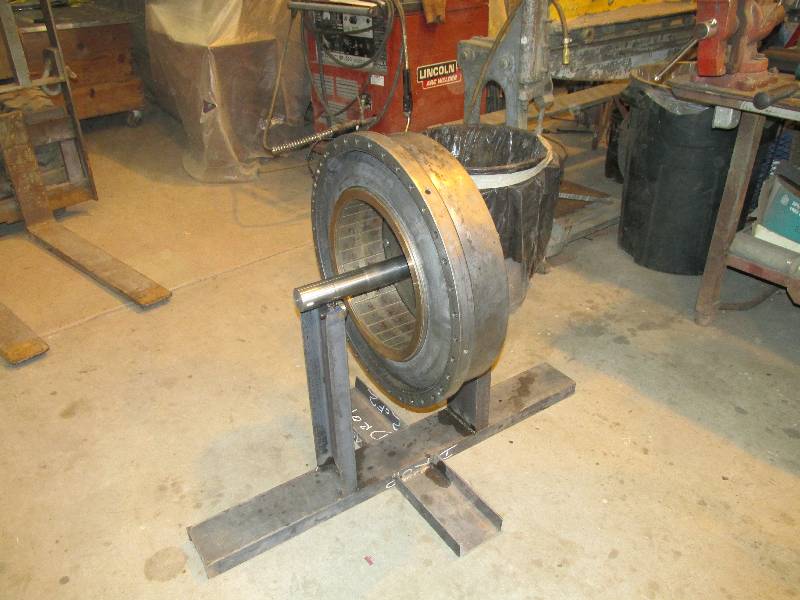
A couple of special tools had to
be made in order to proceed with the process. It was
necessary to locate the heavy side of the drum and rubber assembly.
Bill made a mandrel to which the drum would be bolted for
balancing but, the mandrel itself had to be balanced so it would not
contaminate the process. We also made a test stand that had 4
ball bearings upon which the mandrel shaft would rest and be free to
turn. After the mandrel was balanced by Unico Mechanical of
Benicia, Cal., it and the drum were
set on the bearings, the assembly turned itself so the heavy side was
down and Bill marked the light side.
 |
 |
 |
 |
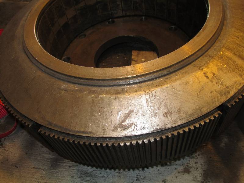
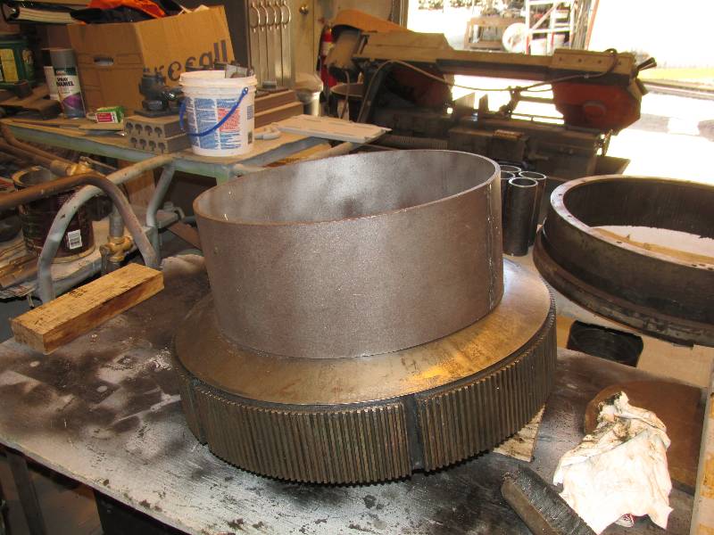
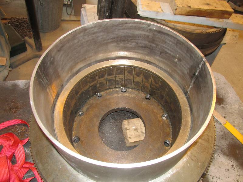
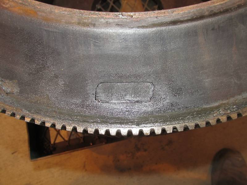
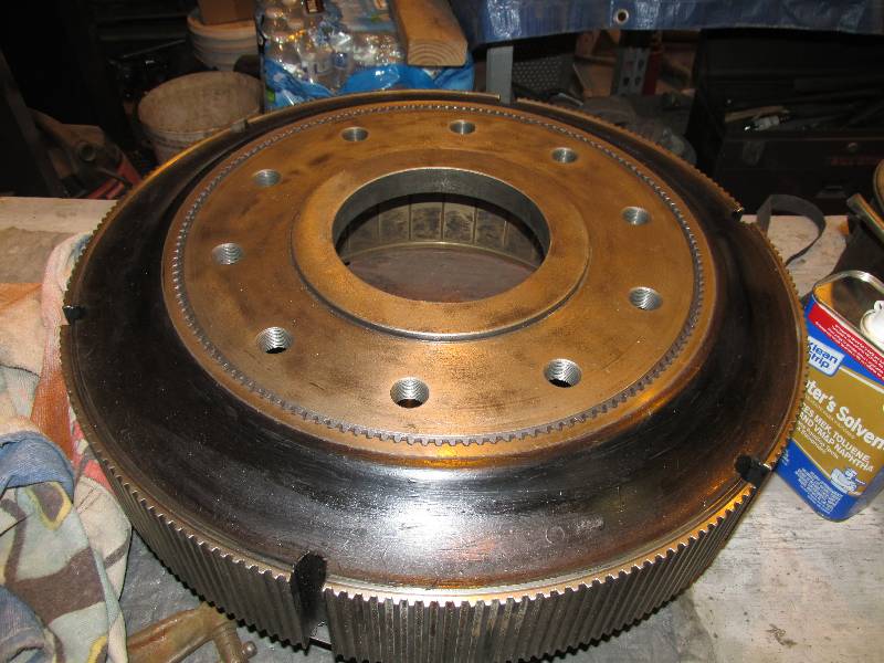
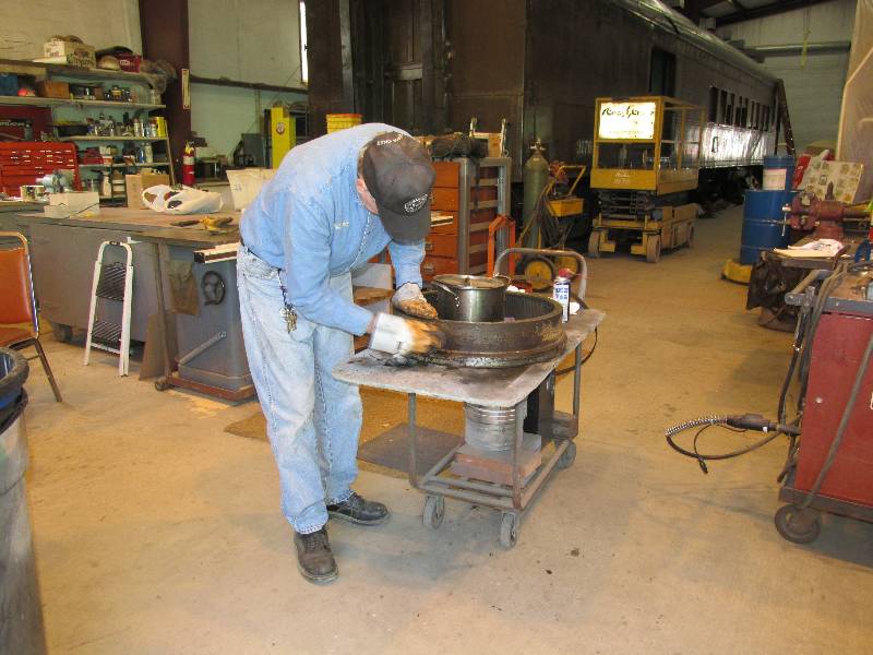
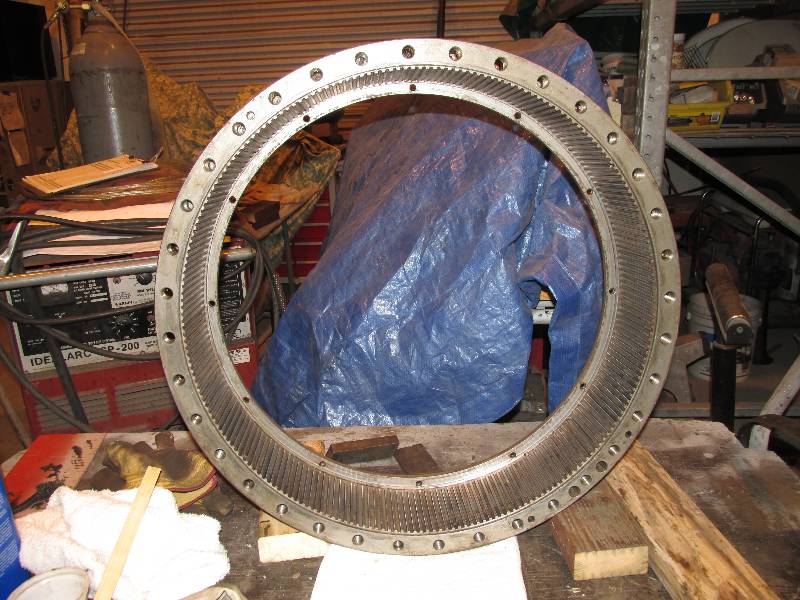
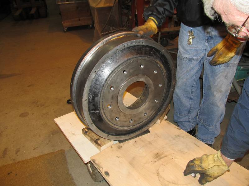
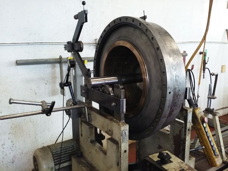
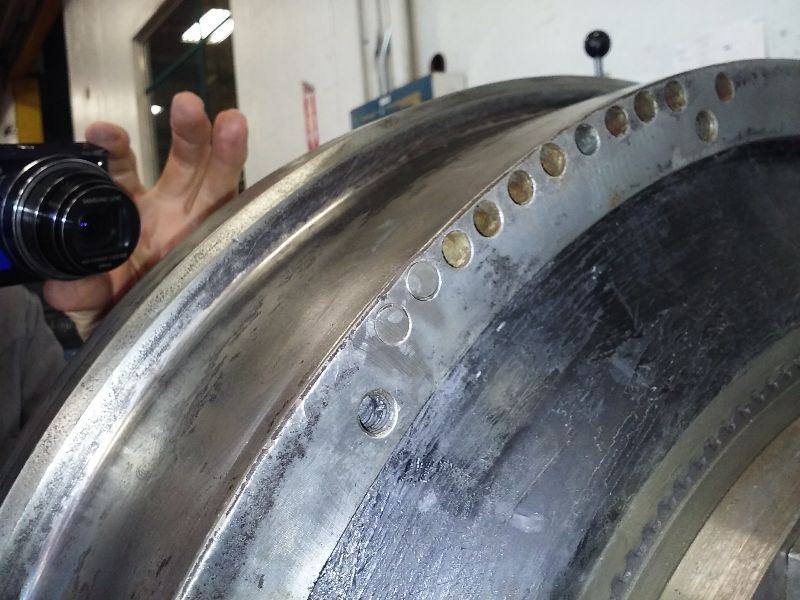
Rich cleaned the outer ring
and prepared it for installation. Note in the second
photo that
there are bolt holes all around the rim of the ring but there several
extra holes at the lower right edge. The evenly spaced holes
are used to attach the coupling assembly to the degree plate on the
crankshaft of the engine. The extra holes were put there
during the original balancing process 56 years ago. These
holes created a light spot on the ring which was mounted 180 degrees
away from the light spot on the drum assembly. Getting the
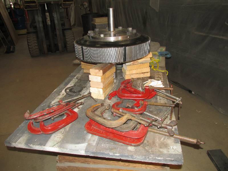
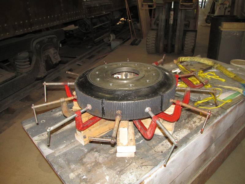
ring teeth engaged with the teeth on the drum assembly was quite a
process, requiring the use of 12 clamps to slightly compress the rubber
of the new resilient part. Once the teeth were engaged, the
assembly was moved to the hydraulic press to complete the job.
Now, the assembly would be taken back to Unico Mechanical for
final balancing.
 |
 |
 |
 |
 |
 |
 |
 |
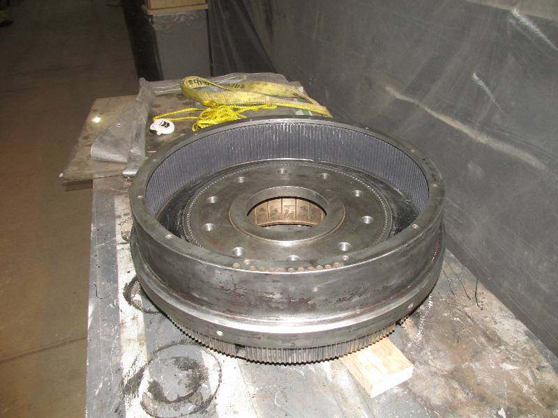
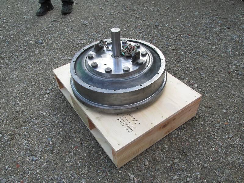
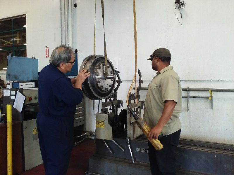
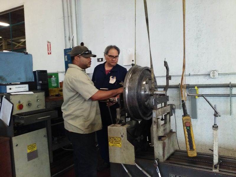
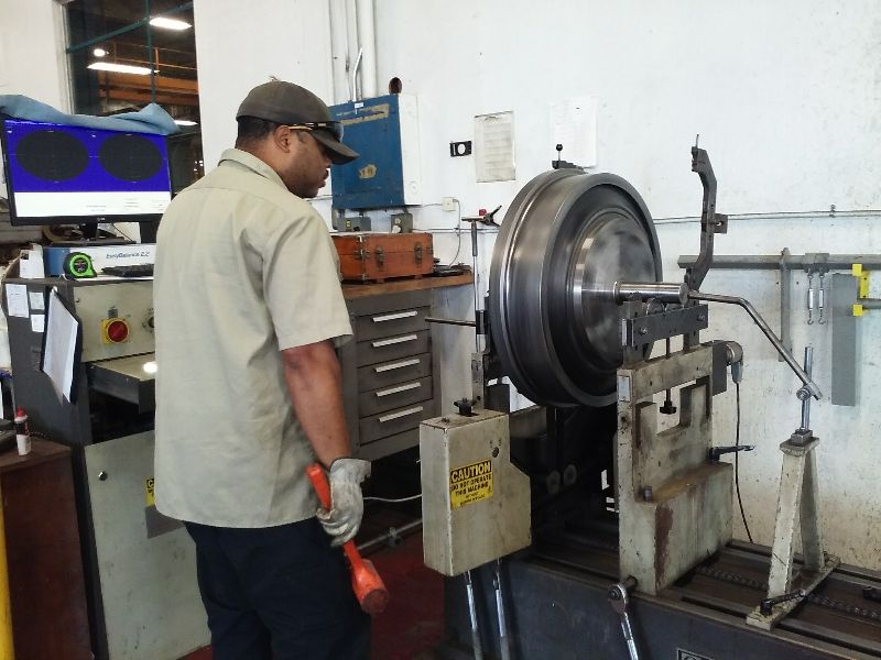
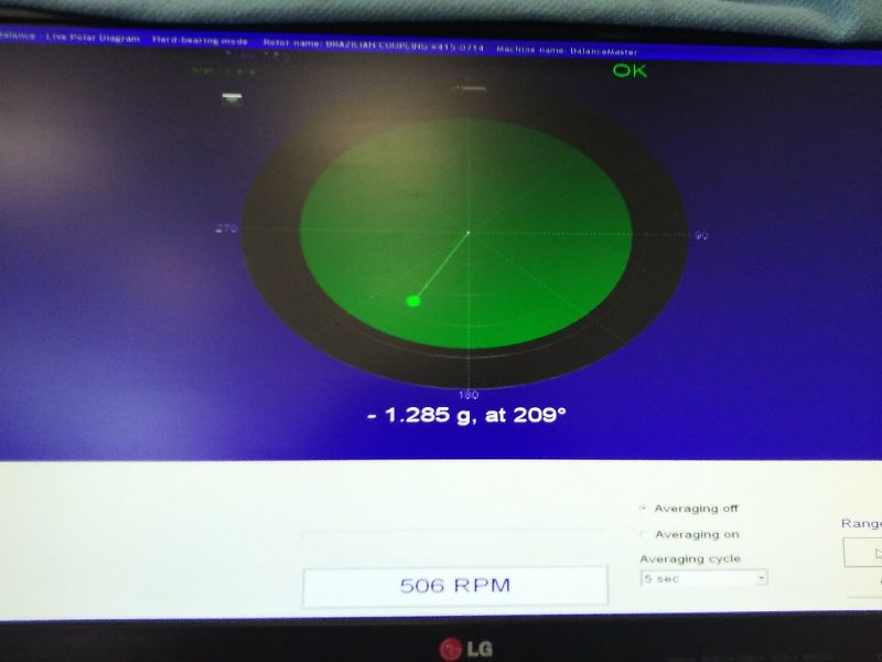
Back at Unico Mechanical in
Benicia, the coupling was removed from its shipping carrier (which was
made to fit
in the back of my car), weighed (290 pounds including the 40 pound
mandrel) and mounted to the
balancing machine. While this was a computer controlled process,
it still required a great deal of thought and knowledge on the part of
the technician. We were fortunate in that most of the imbalance
could be corrected by adding weight to the original lightening holes.
In the end, the process resulted in a well balanced coupling.
It will be stored for a while so we can complete some preparation
work on the end of the engine.
 |
 |
 |
 |
 |
 |
 |
 |
Return To Main Page