|
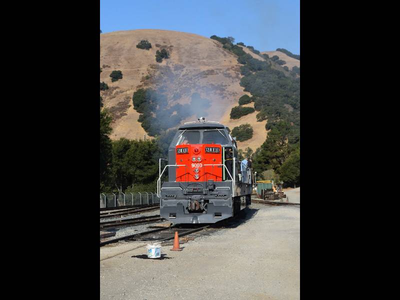
Southern
Pacific 9010
Mechanical Work
Page 4
--
Update December 13, 2016 --
Injectors!!
This project has been at the top of our need-to-do list for
quite
some time and we recently were offered a set of rebuilt injectors from
the Diesel Traction Group in the UK (http://www.westernchampion.co.uk/)
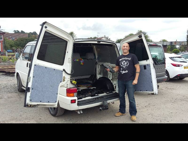
at a reasonable price. We were forced to replace
our
injectors because the originals were stuck from the years of sitting.
Ordering and
paying for the replacements was very simple but getting them to the US
proved to
be quite a struggle. Our crew member Rob made a 400 mile
round trip from Plymouth to pick them up,
carefully boxed them and arranged for shipment through UPS.
Rob
packaged the injectors and some spare parts in 5 boxes so that each box
would weigh under 50 pounds and not be too hard to handle.
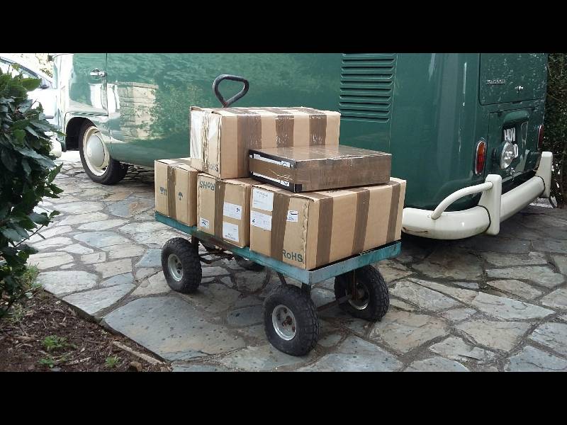
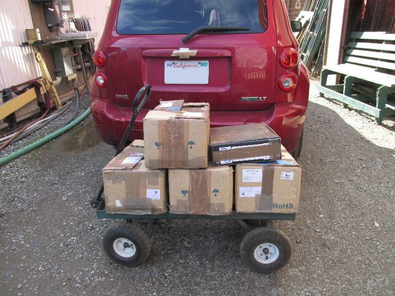
Good
old UPS managed to get 2 of the boxes delivered but 3 of them were
rejected in the UK and not only were we not told why but we could not
get a refund on the shipping! Three of the boxes were
returned to
Rob who repackaged them and put one back in UPS. This box
sailed
right through the system but we decided to try Fedex for the other two
deliveries. Fedex was superb and I had the two boxes as
scheduled.
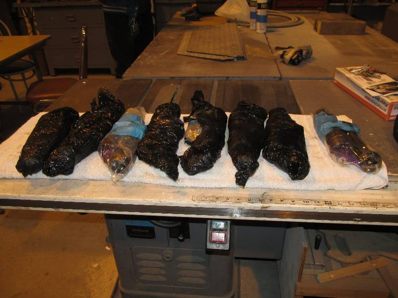
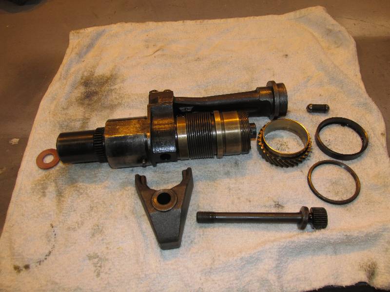
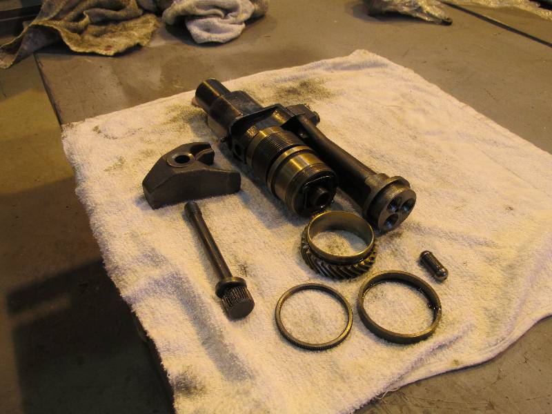
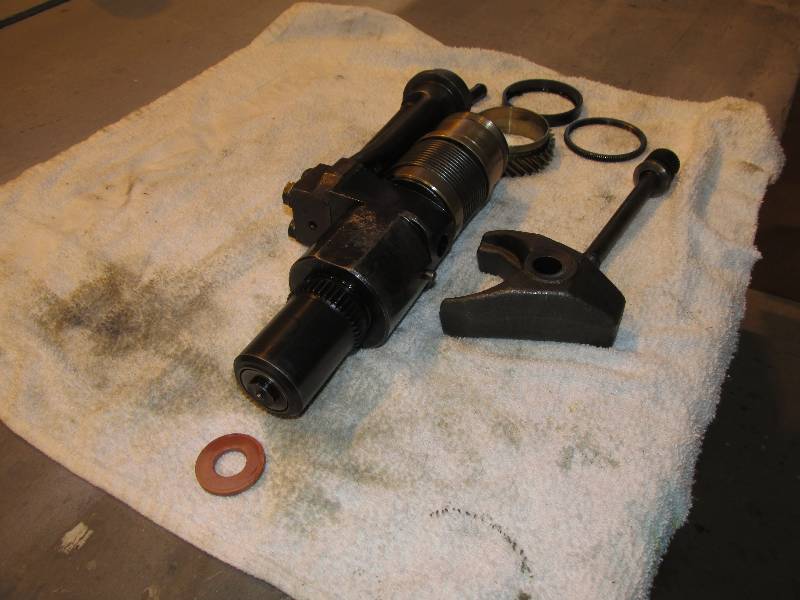
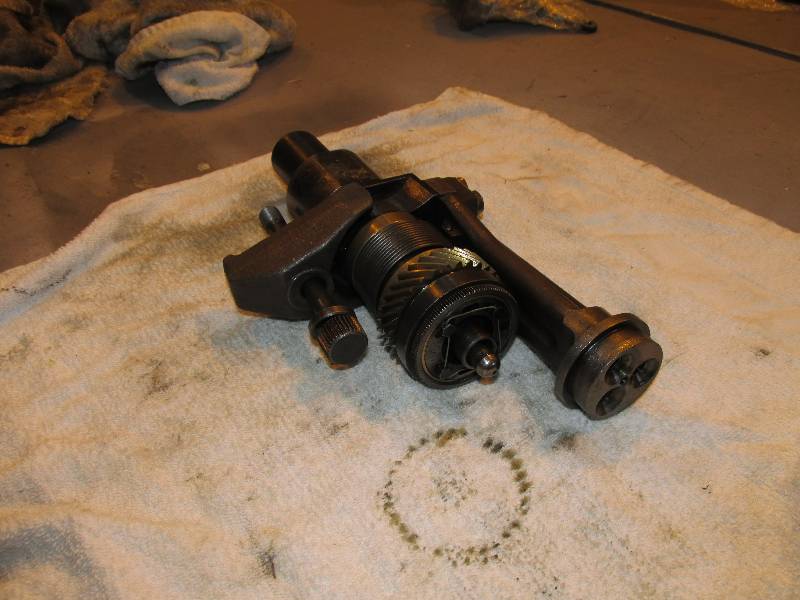
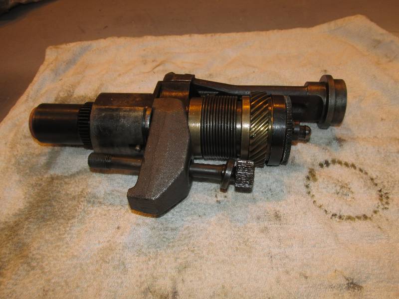
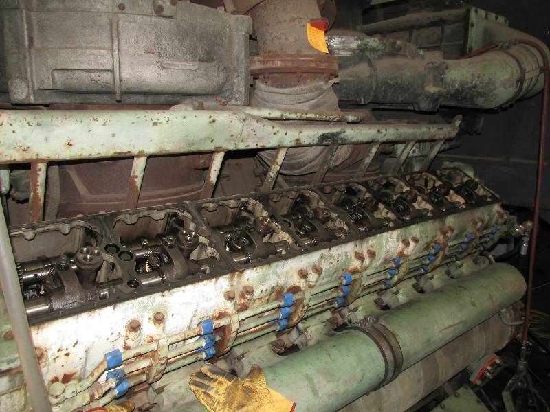
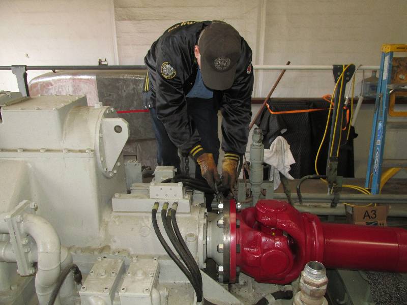
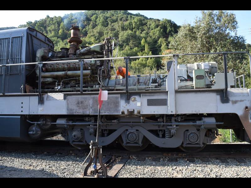
The injector is almost like a kit.
The parts are installed in a specific order in
order to clamp it into the head and adjust the fuel flow.
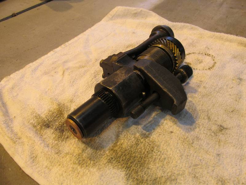
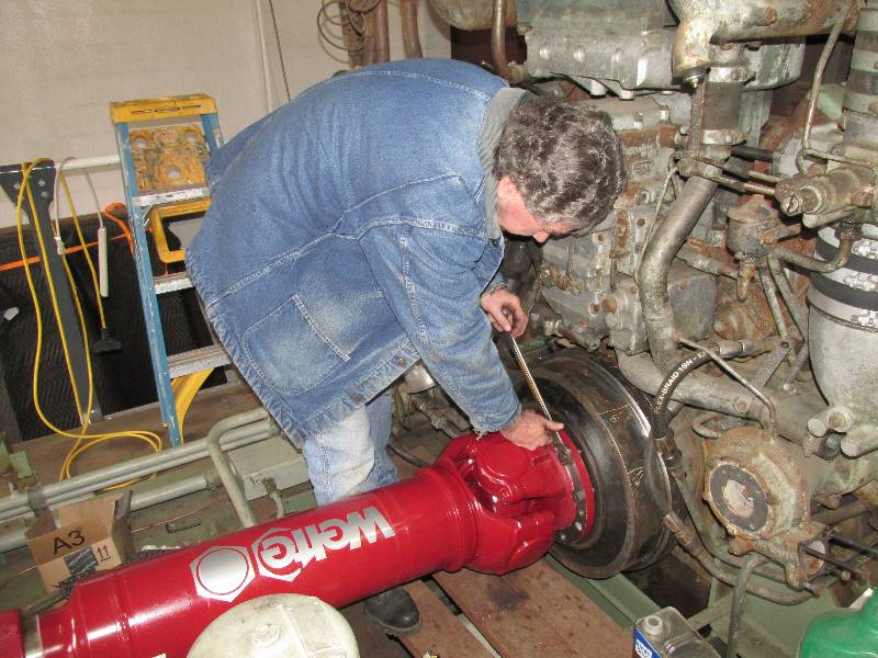
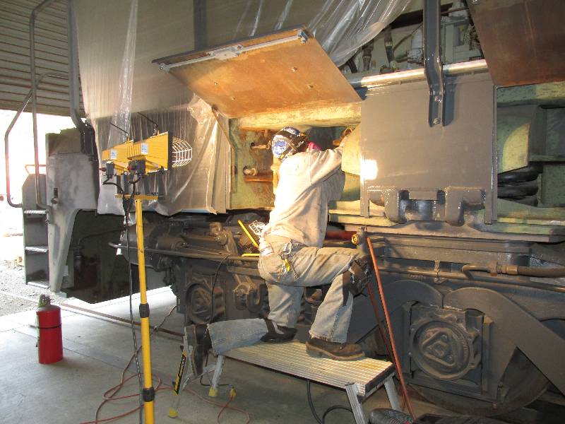
Installing the injectors is unlike
anything
found on domestic US engines. The process requires a number
of very special Maybach tools, a lot of patience and a fair amount of
time. Here follows a few photos of the installation.
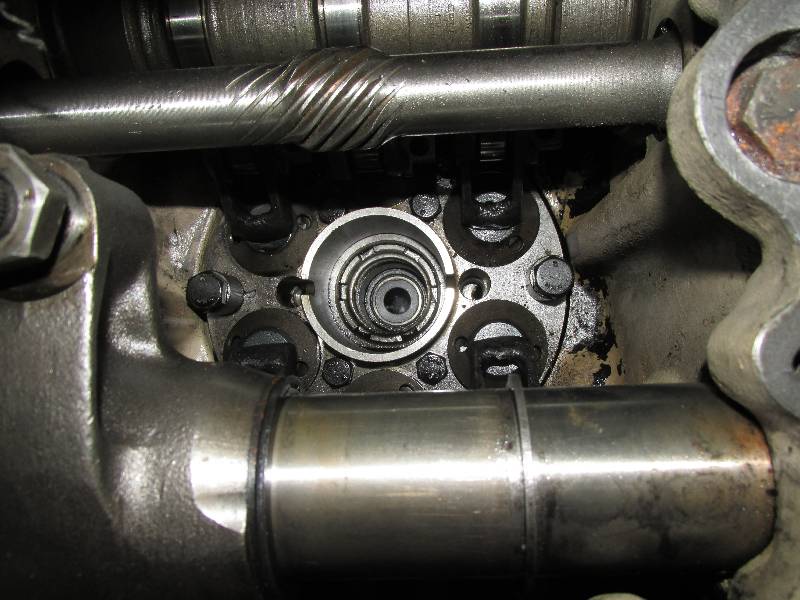
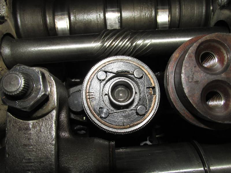
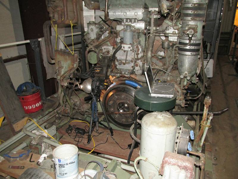
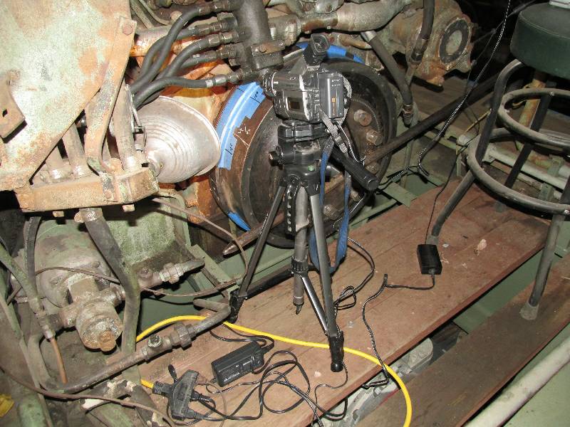
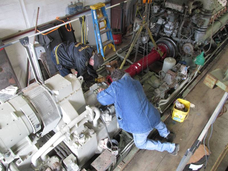
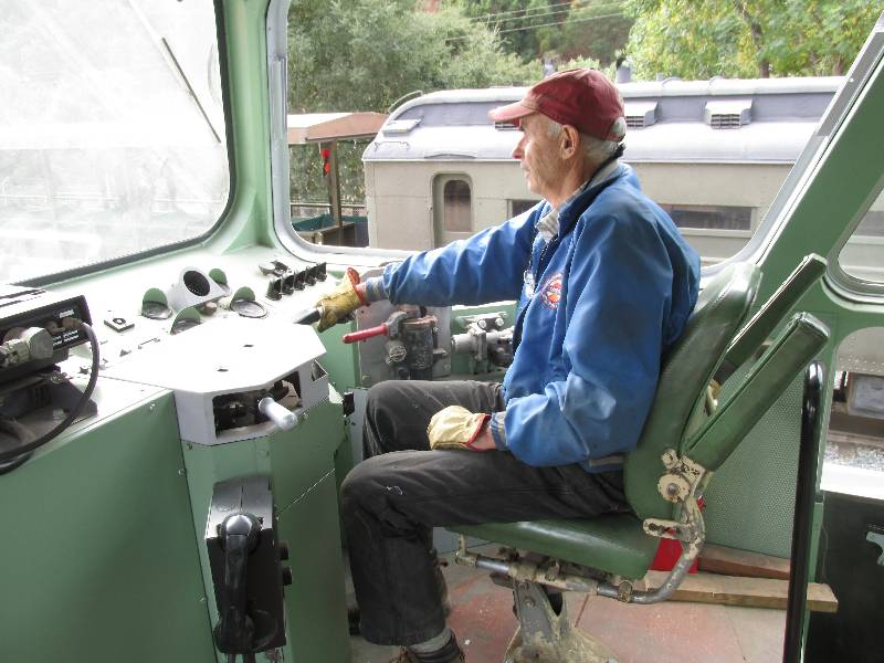
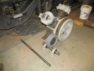
Part
of the injector installation requires that the crankshaft be carefully
barred over to a specific spot for each injector. This was
much
easier to do without the #1 cardan shaft in place but requires two
people, one to watch the degree wheel on the crankshaft and the other
to bar the engine. With everyone busy on other projects, I
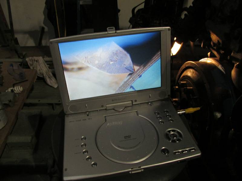
decided to let technology be my helper. A video camera was
focused on the degree indicator and its output was connected to a small
DVD player. I could now bar the engine and see the crankshaft
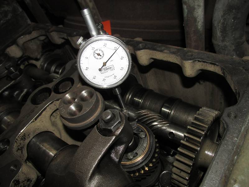
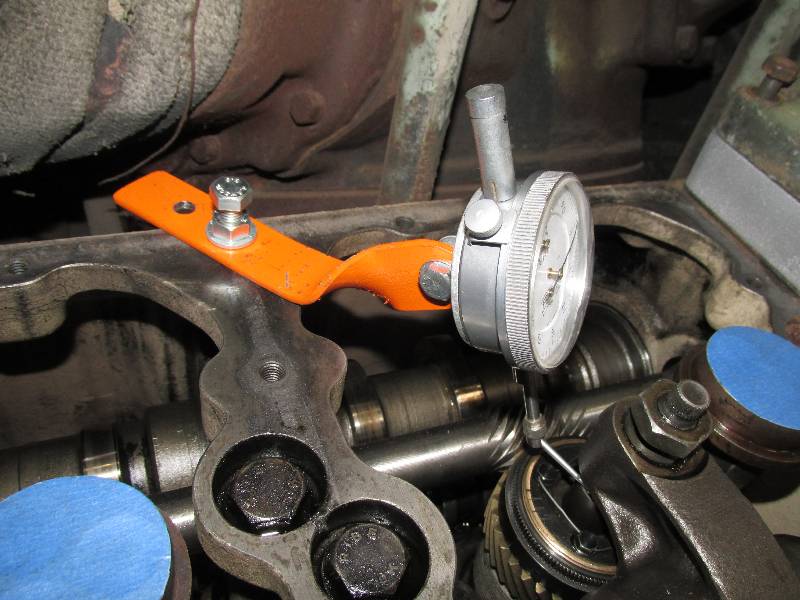
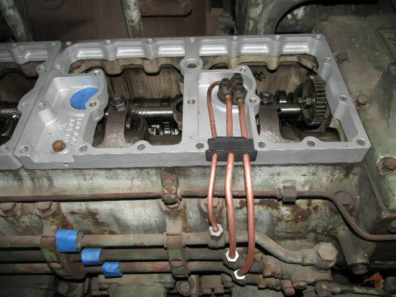
position. The dial
indicator is used to adjust the screw on the end of the injector rocker
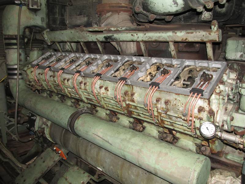
arm and thus the injection timing. With all the injectors
timed,
the cam box cover frames and fuel lines could go back on.
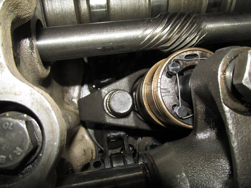
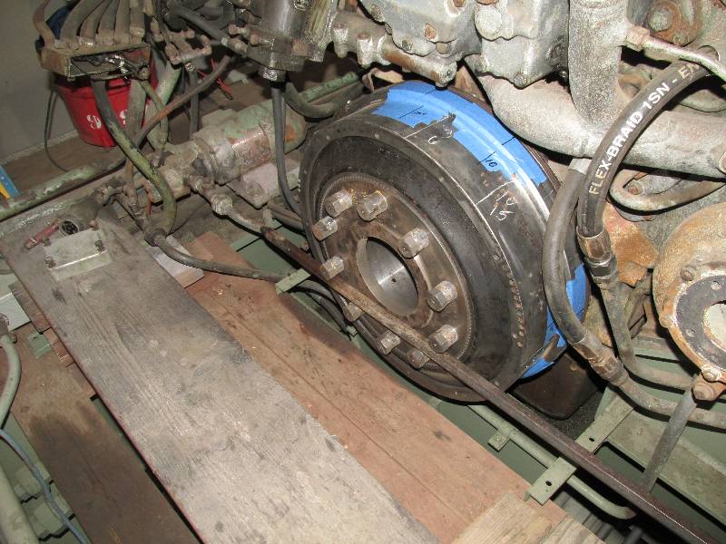
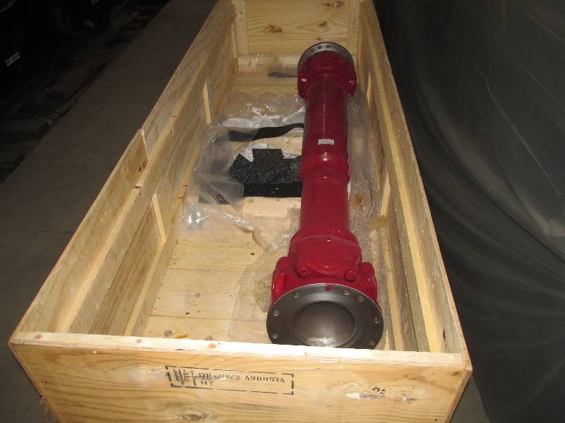
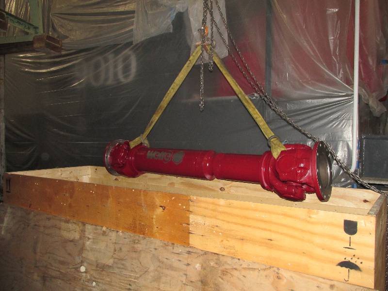
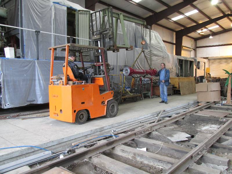
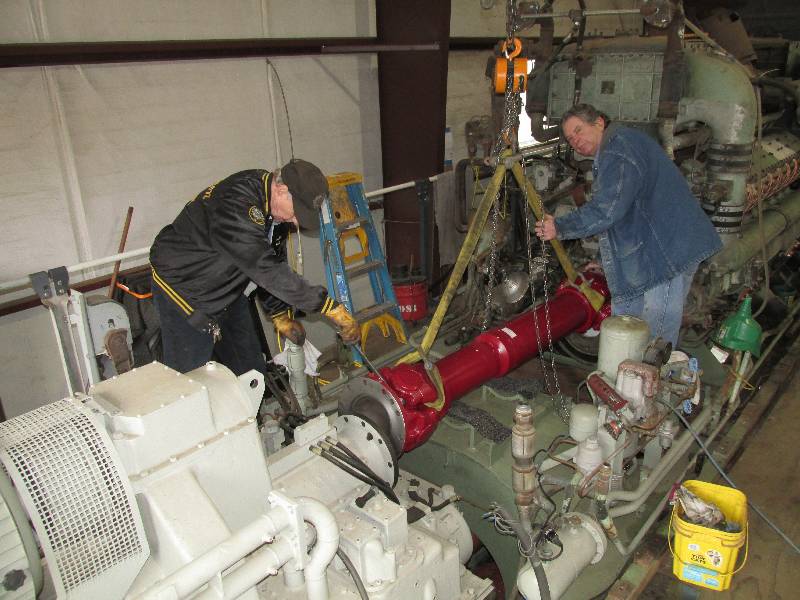
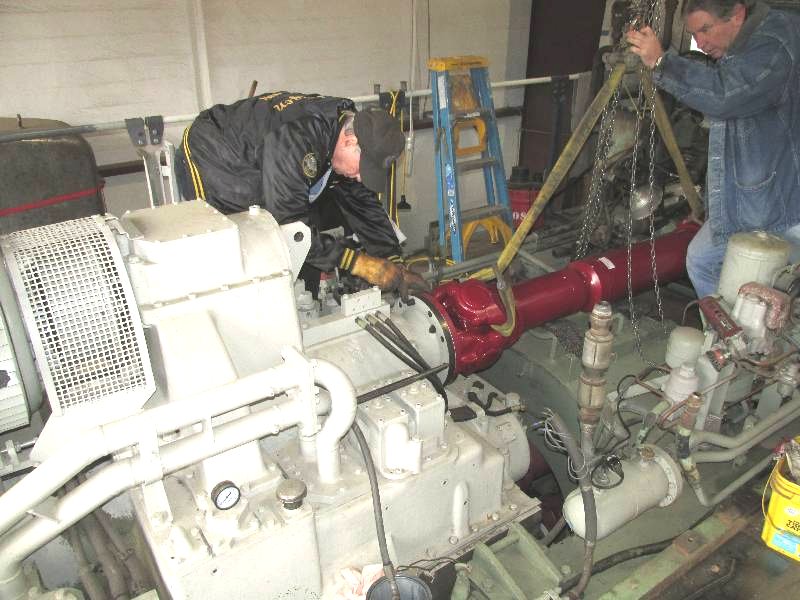
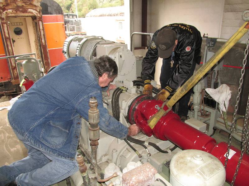
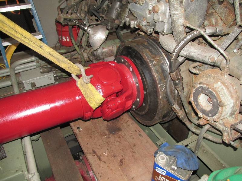
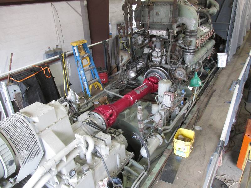
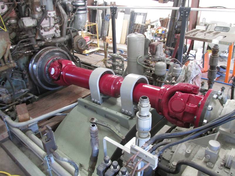
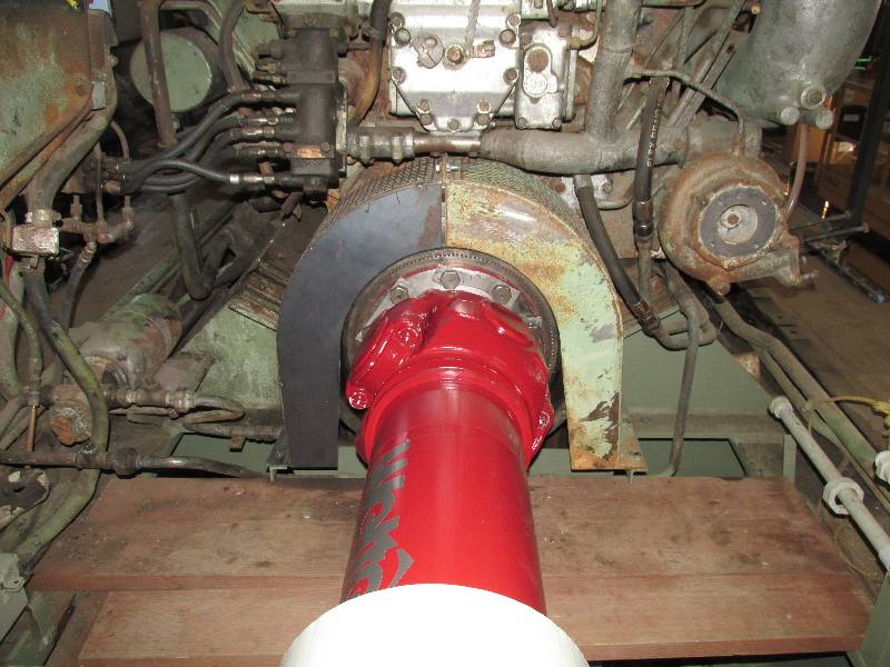
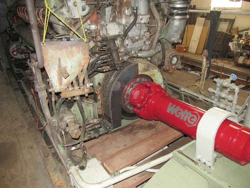
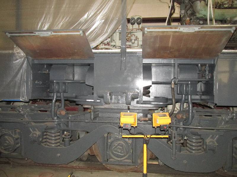
Once the
injectors were in and timed, we installed the last of the new cardan
shafts from The Welte-Group in Germany. We owe a great deal
to Mr. Egon Welte for his help with the project. Dennis and
Rich muscled the 975 pound shaft while I supervised and ran the fork
lift. Still to
come are torquing the bolts and installing the shaft's safety straps.
The shaft and couplings will eventually be
completely covered to conform to FRA regulations.
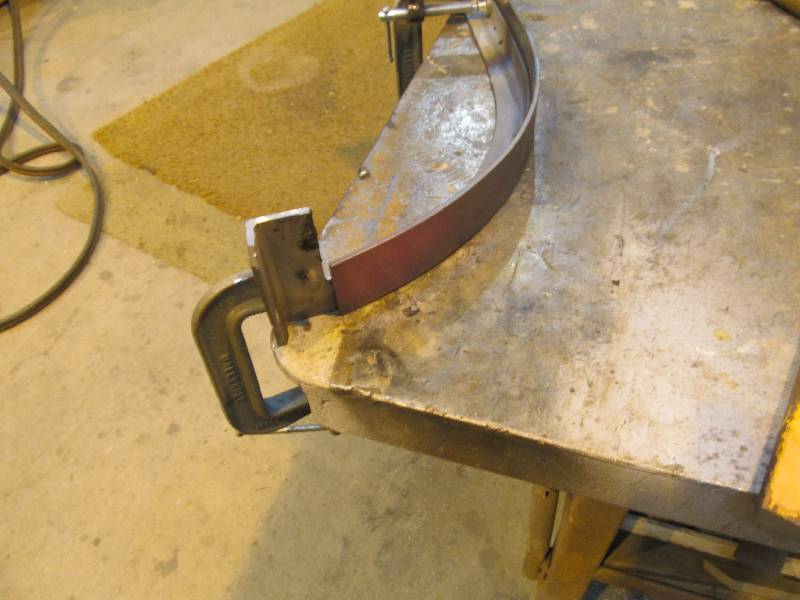
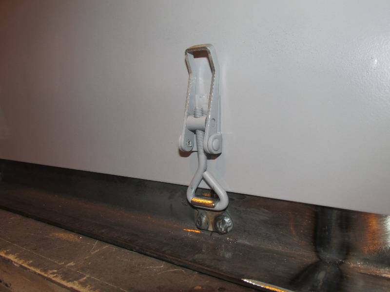
--
Update December 30, 2016 --
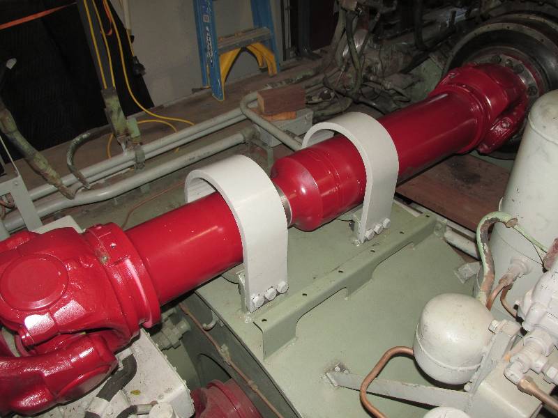
After
torquing the coupling bolts, the next operation on the cardan shaft
was the installation of the safety straps. These were made
from
3/4" thick steel and formed by our friends at Melrose Metals.
At
some point in the future, a cage will be made that will duplicate the
one that was there originally.
For our final effort in the 2016 year, we ran
the engine over using the power of the dynastarter. The fuel
pump
was running as was the pre-heater and the compression relief valves
were open. It was a payment to ourselves for the
hundreds of
hours of preparation work that preceded this moment. An
attempt to start the engine is not too far in the future. The
following video is courtesy of the editing skills of Bob Zenk.
--
Update February 03, 2017 --
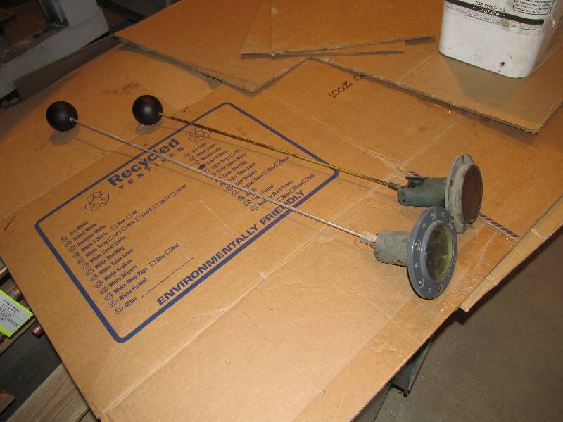
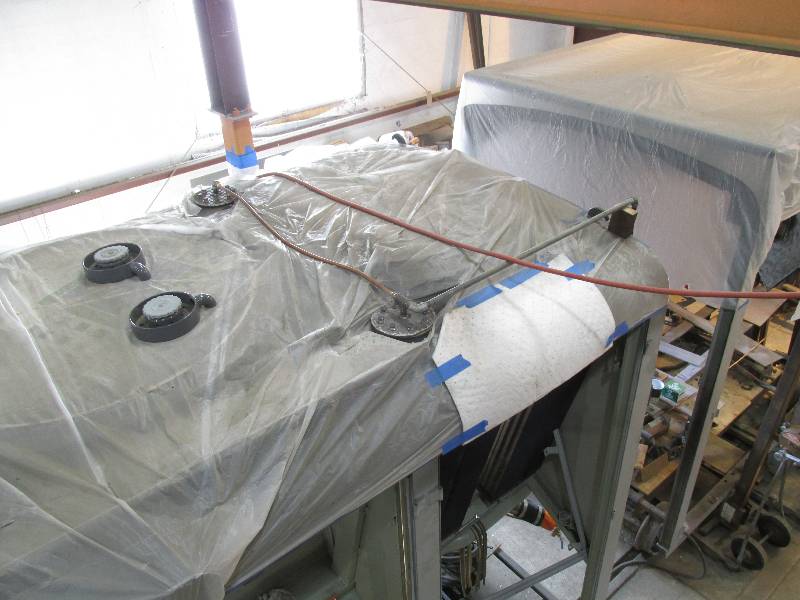
When
we received the locomotive, the fuel gauge on the right side of the
tank indicated about 1800 gallons while the one on the left was
unreadable because the fuel had leaked into the gauge face.
The
gauge on the right was an EMD component so we bought an identical gauge
for the left. We knew that the fuel had been in the tank
since at
least 1980 so decided to empty the tank and start fresh. Once
the
tank was empty, the gauge on the right still indicated 1400 gallons!
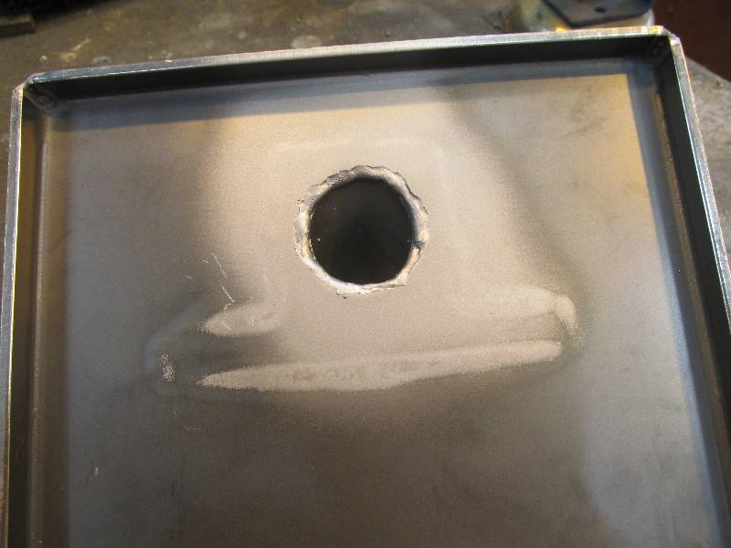
Once removed, the gauge level arm proved to be about 6" too
long
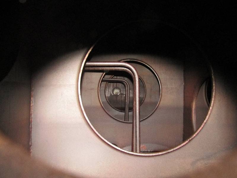
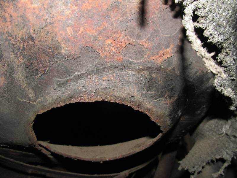
and was trapped by a tank baffle. The second photo was taken
looking through the hole for the right hand gauge and looks across the
tank. The pipes seen are the suction lines for the engines
and
engine pre-heaters. The 9010 now has two functional fuel
gauges
on the tank.
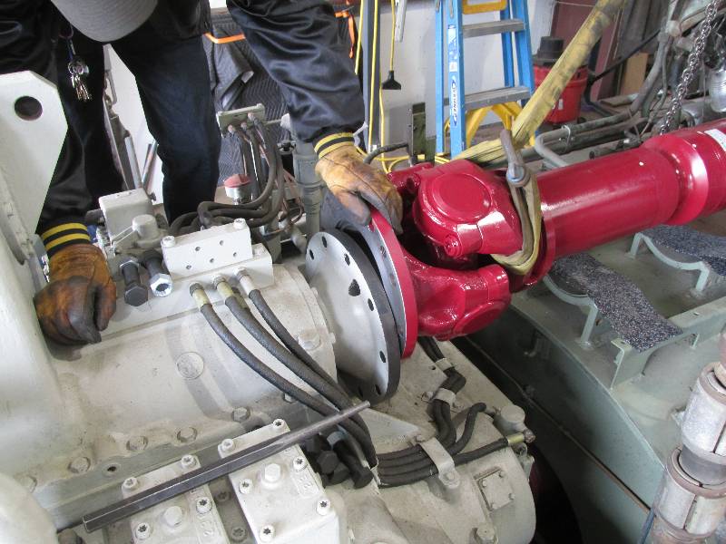
FRA regulations require that
rotating apparatus
be covered to protect employees. The resilient coupling and
#1
cardan shaft (rear engine) fall under this requirement. There
was
one half of the coupling cover left on the rear engine and the same
half remained on the front engine. The half cover from the
front
engine was modified to become the left side for the rear coupling.
Design is progressing for the cardan shaft cover.
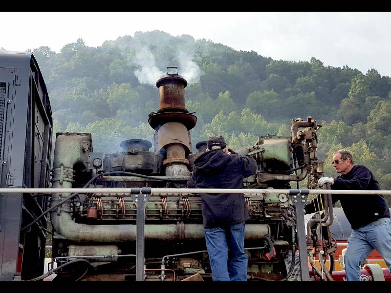
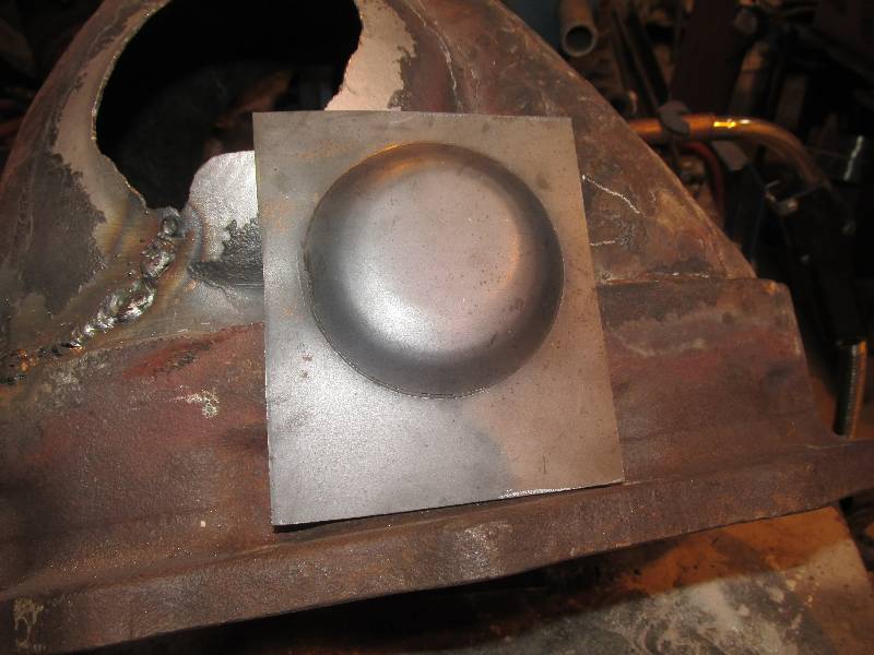
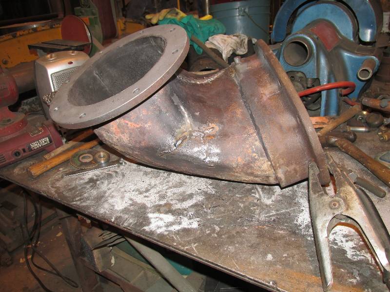
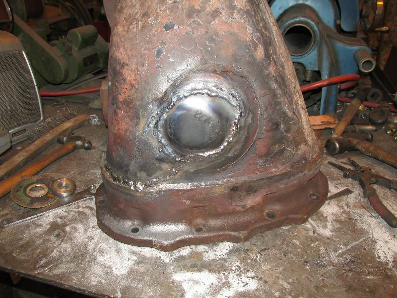
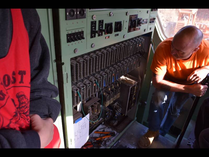
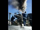
On January 17th, we attempted to start the rear engine. We
have an old, used set of batteries in the 9010 so we used jumper cables
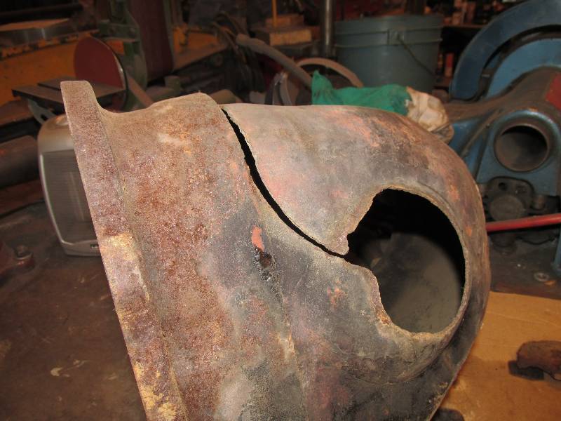
to access the batteries on another locomotive. We were not
successful, mainly because of the discovery of a very defective exhaust
elbow on the rear turbocharger. There is a short video of the
event on Youtube at: Maybach start, first attempt.
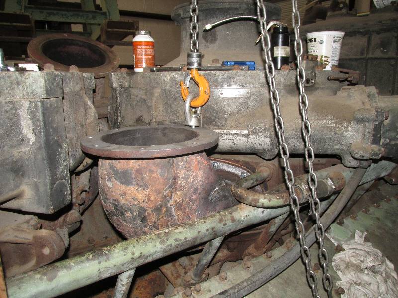
The
video comments give more information about the trial. After
removing the elbow, the rear turbo was found to be frozen so we had to
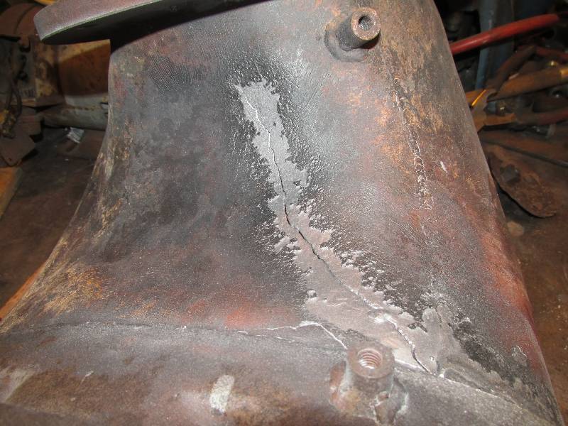
deal with that. The elbow was repaired and another start
attempt
will take place soon. The metal is quite brittle so was very
difficult to weld. I hope the welds hold! If not,
we will
be digging into the front engine for a replacement.
--
Update February 18, 2017 --
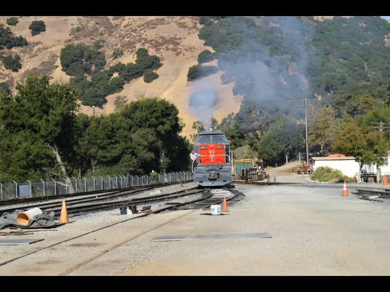
On February 14, 2017 we tried for the second
time to start the rear engine. This time was much more
successful! There is a video of the start on Youtube at Maybach start, second attempt.
We were amazed at how smoothly the engine ran after being
dormant for nearly 50 years.
 |
--
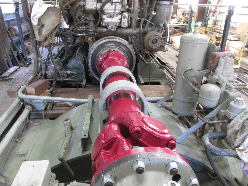
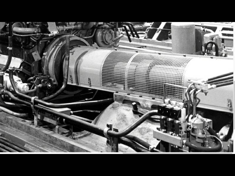
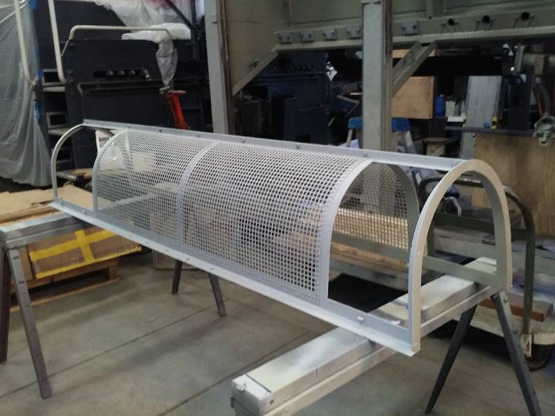
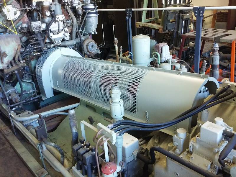
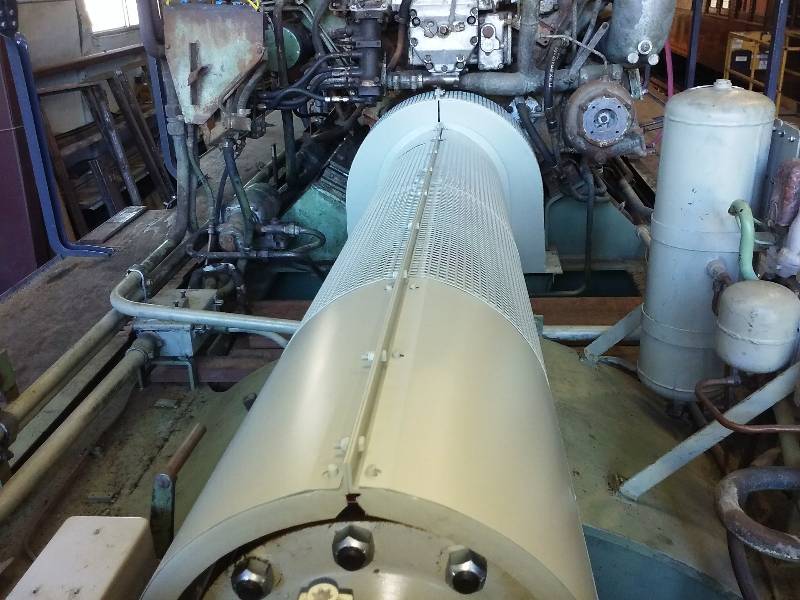
Update June 21, 2017 --
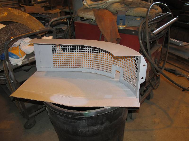
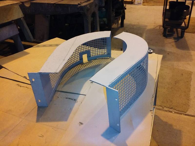
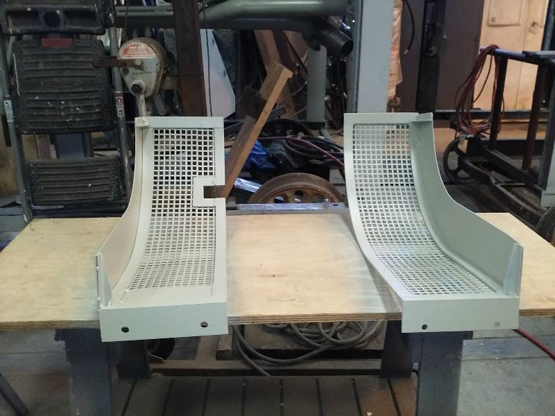
Prior to starting the engine, the new cardan
shaft cover was completed and installed. The removable panels
at the front and rear are for access to the grease zerks on the
universal joints and the sliding coupling.
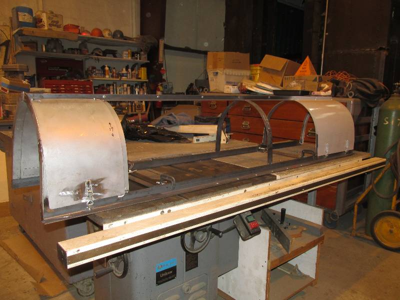
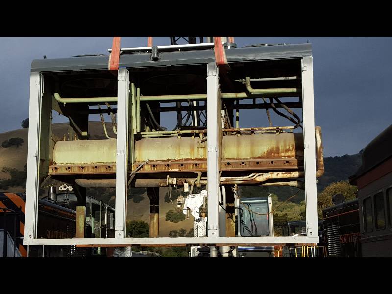
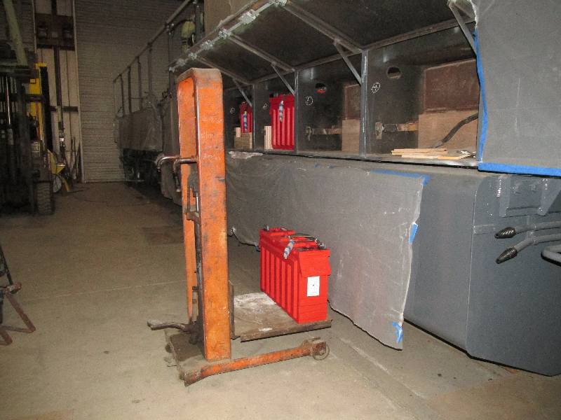
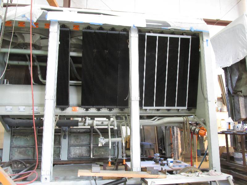
Now
that we have a running engine and a seemingly functional
transmission, the specter of our empty cooling hood again rears it ugly
head. We have been discussing this issue for several years,
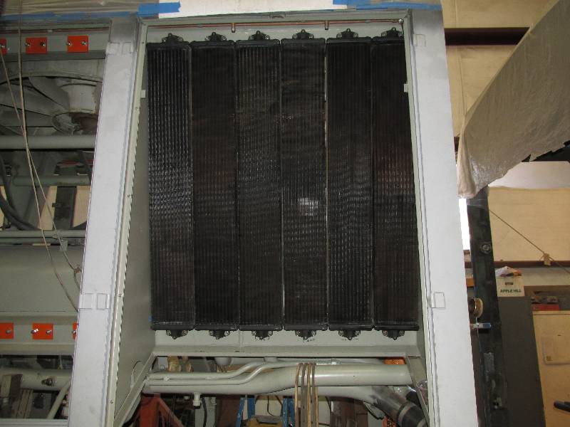
with many ideas both reasonable and far-fetched on the table. The
hood is divided
into 6 sections, 3 on each side with 6 cooling elements in each
section. The first 4 elements on each side (right of photo)
are dedicated to the
turbocharger aftercooler cooling and the rest of the 24 elements are
for everything else.
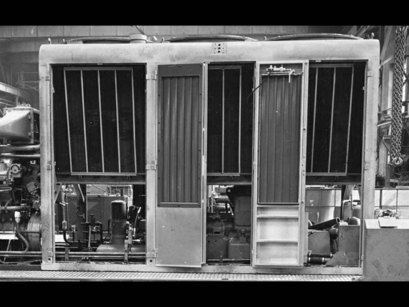
Bill
came up with the brilliant idea of taking an original radiator element
to a local shop to see if there was something they could do.
At the shop, Jim removed the torn up radiator from the ends
and figured out how to attach a new core to the ends. We had
6 original elements from
which we could build 6 new units. We decided that these would
be mounted in the right front hood section and this would be our
"display bay," showing what the original cooling system looked like.
What would happen to the rest of the hood was, as I
mentioned, open to debate.
It wasn't until our friend and crew member Lorenzo Pantani in Italy
came up with plans for cooling element ends to be made on a computer
controlled milling machine that we realized we could create elements
that would fit like the originals and give us full cooling
capacity. With a very generous donation from major
project
supporters Dick and Barbara
Harley and the agreement of the PLA Board Of
Directors, we decided to proceed
with the venture.
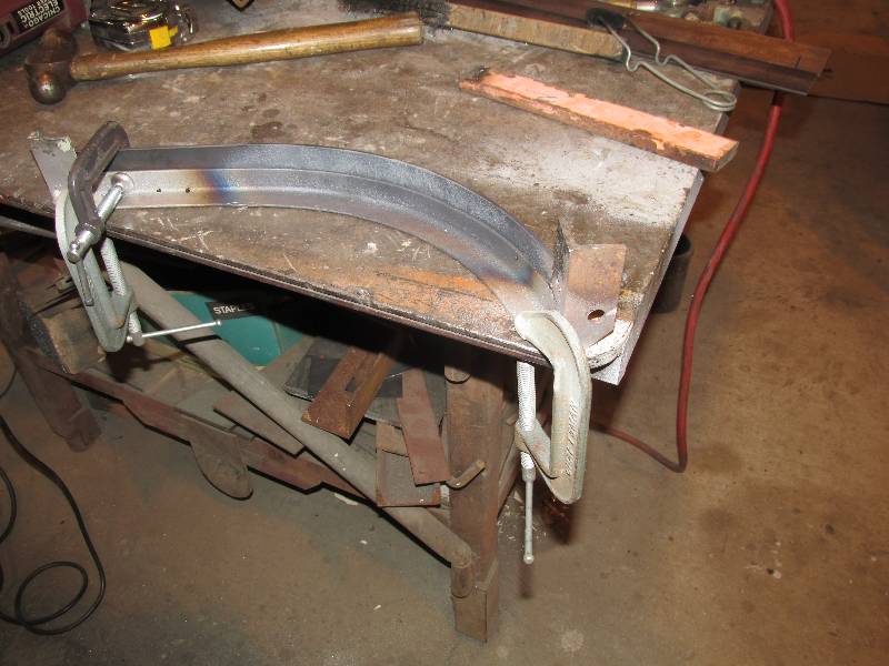
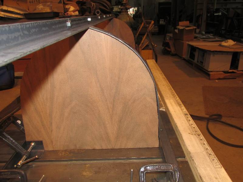
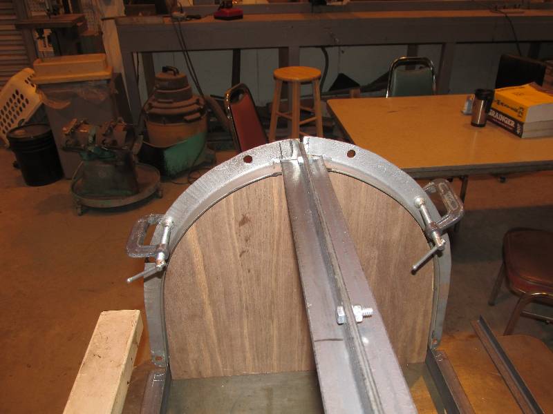
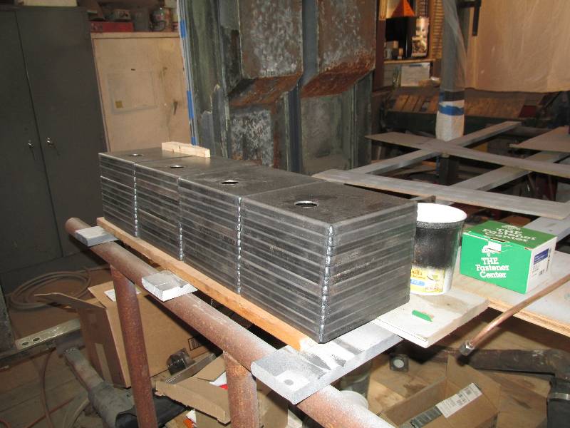
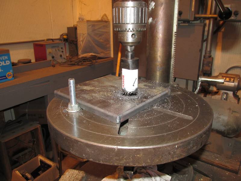
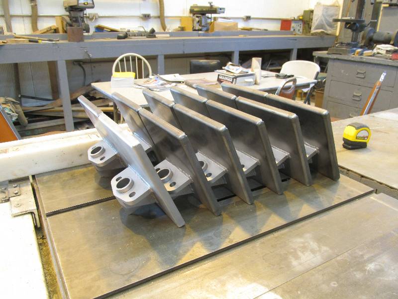
Each end consists of 3 pieces. The "pan" will be soldered to
the end of the new core. The "collar" will be attached to the
"neck" which in turn will be welded to the pan. The collars
(which Bill designed) could have been included in the CNC milling but
it was by far cheaper
to produce them ourselves from DOM tubing, turn them on our lathe and
press them into the neck. During welding, the collar was tack
welded to the neck inside the necks hole. Producing 60 of
these assemblies took quite a bit of time but the results will be
worth the effort. There will be photos of the radiator
elements when we receive some of them from the shop.
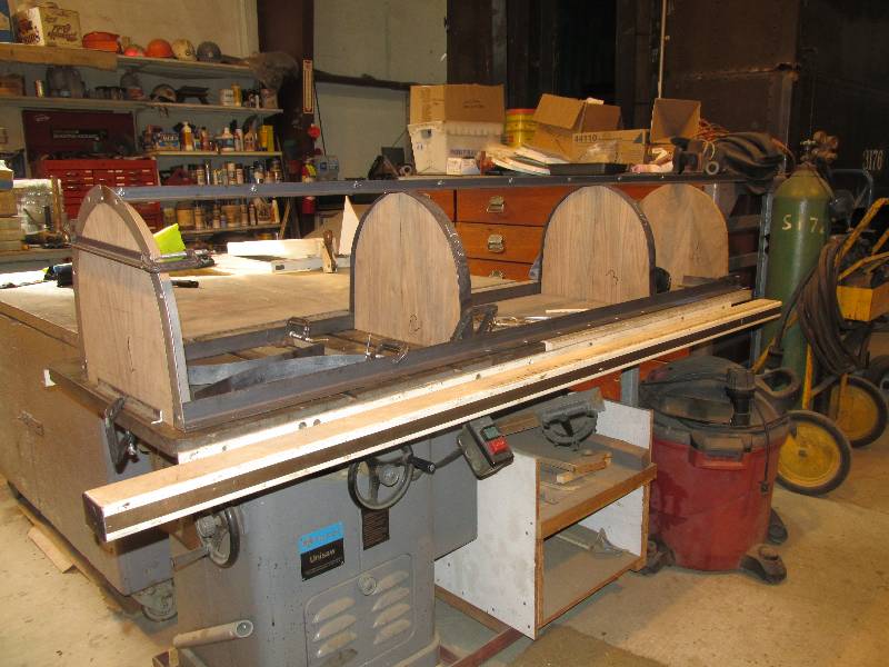
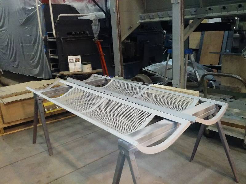
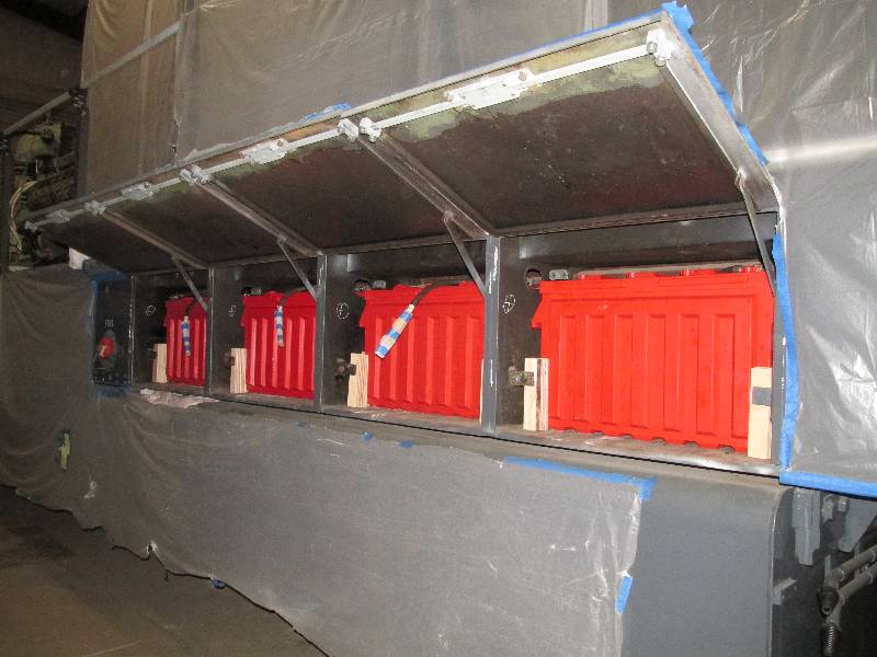
Meanwhile, the last of the
elements using original Behr ends was returned to us and was soon
mounted
in the "display bay". The second photos shows how the hood
will look although from the other side.
We have also began the process of
pressure testing the cooling hood. Back in 2010
when the cosmetic restoration of the hood was done, no thought was
given to a functional cooling system. Times have obviously
changed and we need to make sure that nothing leaks. All of
the water connections for the missing radiator elements have been
capped and all
pipe flanges and other connections closed off. The system
will be
filled with water and pressurized to about 25 pounds per square inch.
The radiator pressure caps are set at 15 psi so the 25 psi
will
give us a bit of extra insurance. There will be more about
this
in a future post.
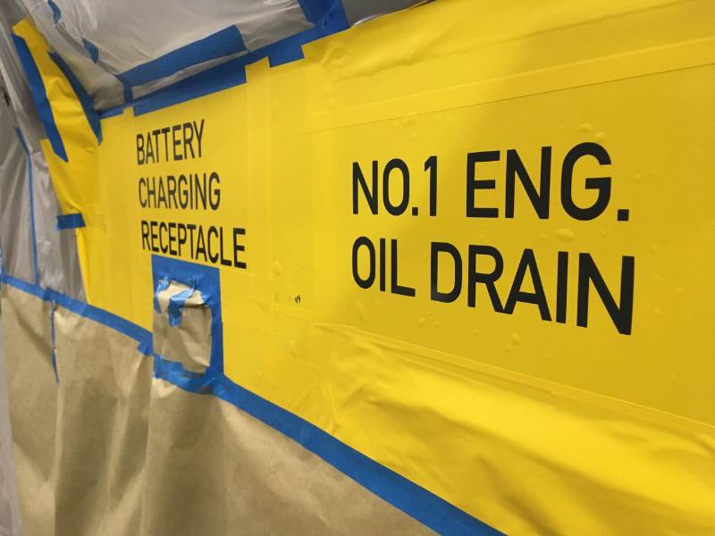
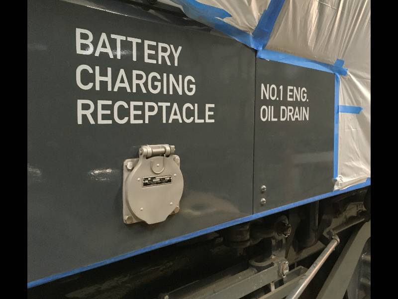
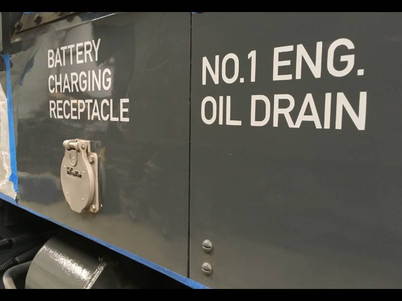
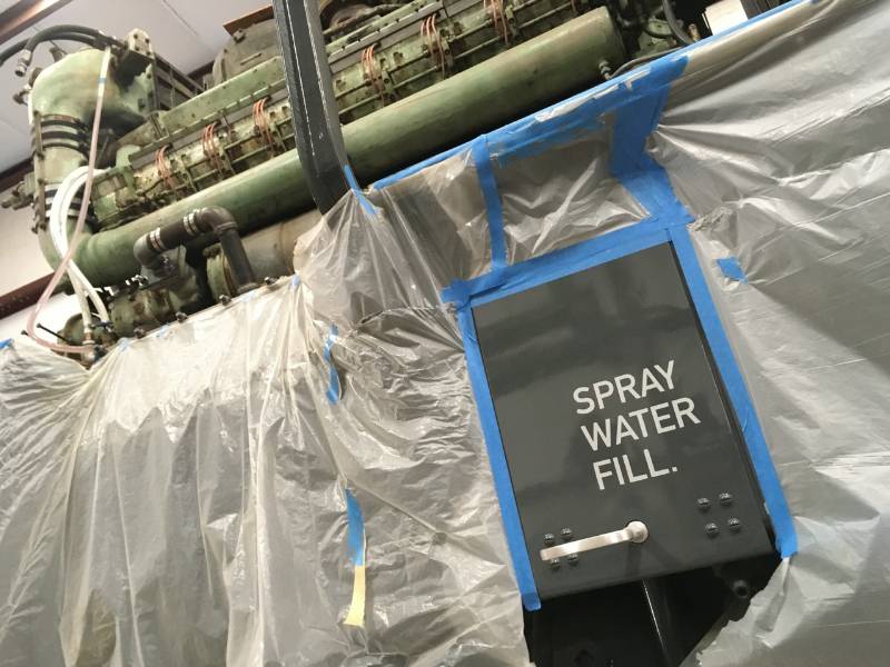
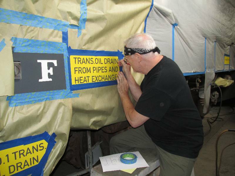
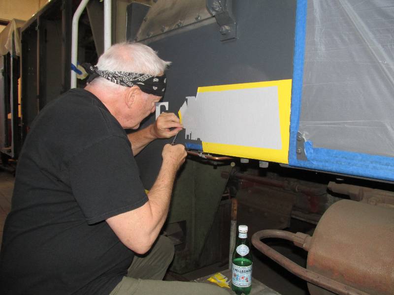
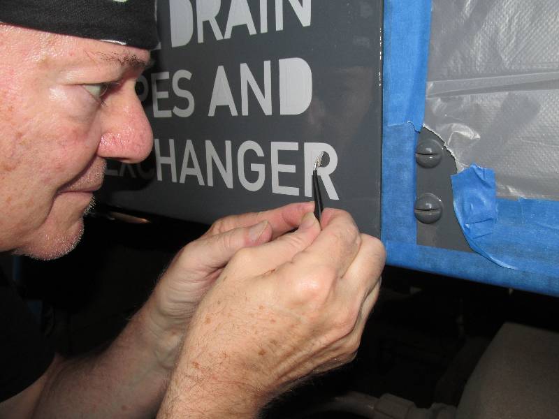
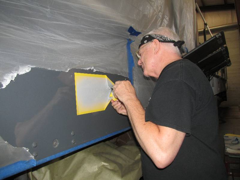
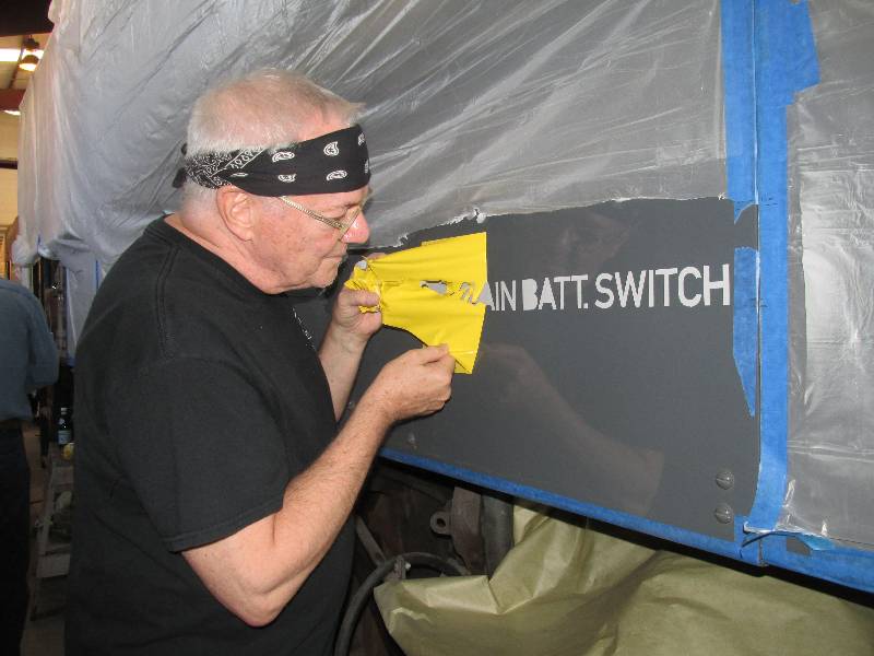
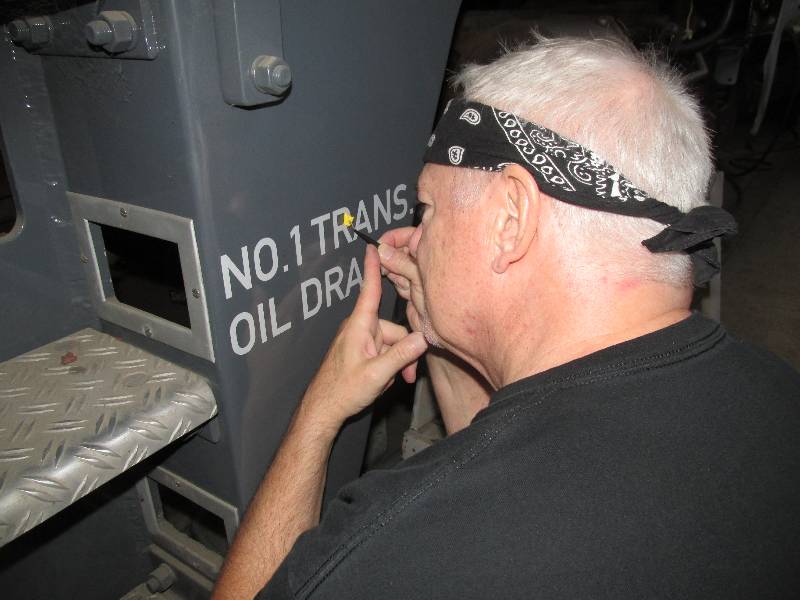
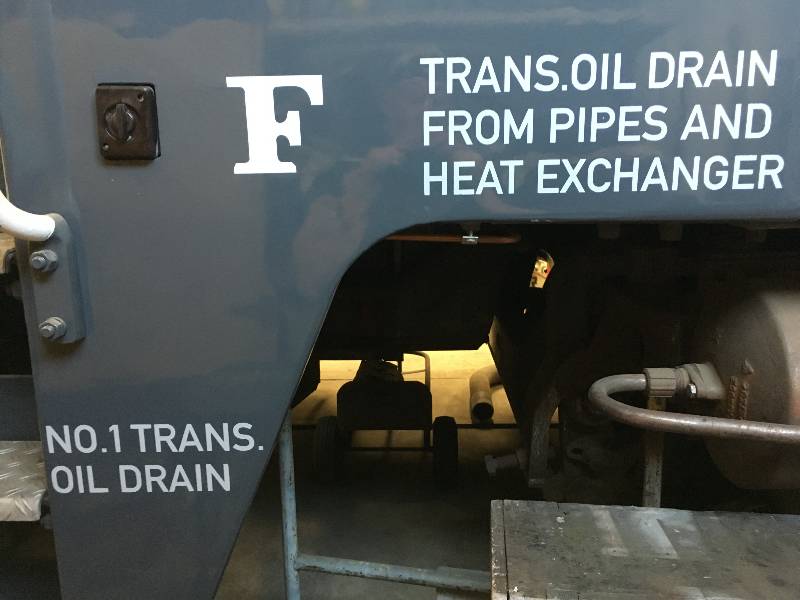
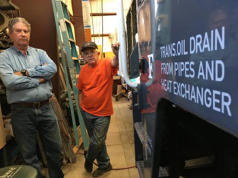
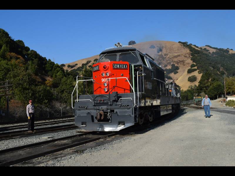
--
Update August 26, 2017 --
Our
buddy and 9010 project Minister of Information Bob Zenk came down from
Seattle this month. His aim was to apply some of the frame
lettering to the 9010 and he succeeded admirably. It is a
rather
tedious process but the "stencils" created by PLA member Chris Hauf
were beautiful and I enjoyed applying paint over them. By the
way, the lettering is in the "DIN 1451" font which is the German
standard typeface as applied to other German locomotives. Bob
also developed the stencil artwork, and determined correct positioning
with his iMac, using detailed photos taken by David Thelen in 1964 and
provided to us by David's brother Lou. The
paint is PPG catalyzed urethane Southern Pacific Lettering Gray as
custom
mixed by our paint supplier, San Leandro Color. Dennis and I
took
some time to stand and admire the work.
--
Update December 24, 2017 --
It
has been nearly 4 months since the last update but work has continued.
Bob does such an excellent job with our Facebook page
that I tend to ignore the web site. So, let's consider this a
year-end update and I will try for more frequent updates next year.
The
big news is that the 9010 moved under her own power. Gerry
was
the first to notch out the throttle and feel the transmission put power
to the rails. Of course, we cannot run the Maybach for very
long
because our cooling is limited to the water in the engine block but
having her move was a thrill. In October Rob came over from
the
UK and we ran her again until the water temperature told us to shut
down the engine. There is a short video of Rob running the
locomotive on Youtube here. The smile
on his face tells the tale.
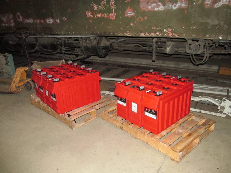
We
purchased a full set (8) of new batteries and are now able to start the
engine without the aid of jumper cables. Our cranking speed
went
up from around 75 RPM to a bit over 200 RPM which makes all the
difference in the world. The batteries we had in the 9010
were a
used set that had been removed from our 80-ton GE because they were
worn out. They served our purpose for a while but the time
came
to send them to the scrapper.
Cooling
system reconstruction is well over 50% completed. As of
today's
date, we need only 11 more radiator cores. The quality of the
work we are getting from Centerville Radiator is outstanding.
After installing 1 or 2 cores, we pressurize the system to 25
PSI
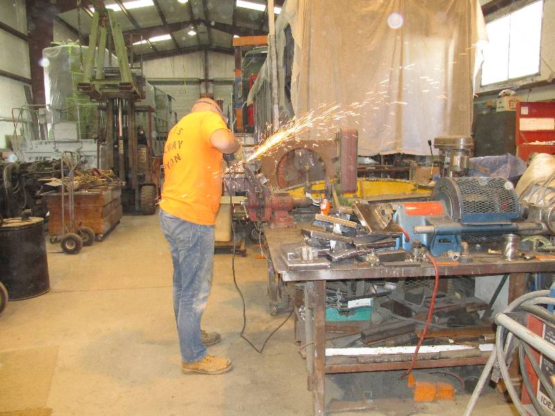
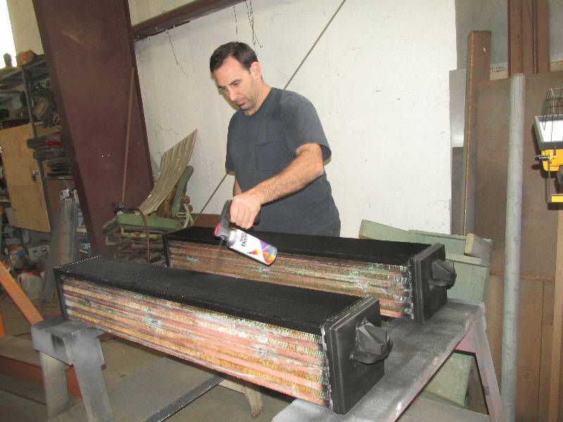
and have had absolutely no leaks. While Rob was here from the
UK,
he put himself to work finish grinding the last of the end caps and
Dave was caught painting a couple of the new cores.
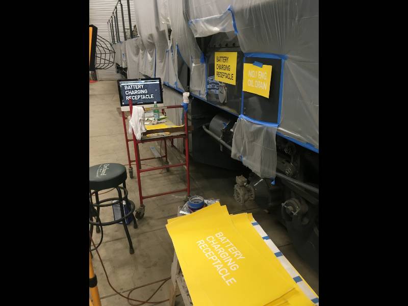
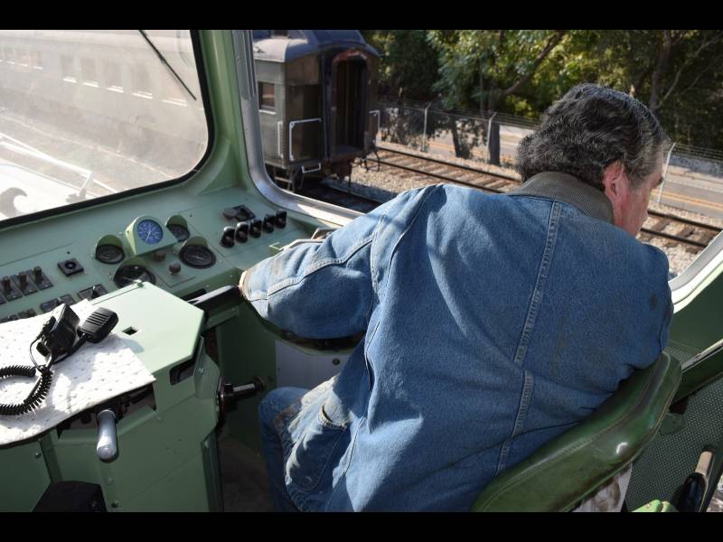
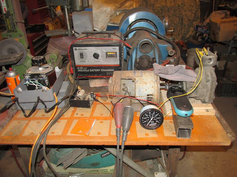
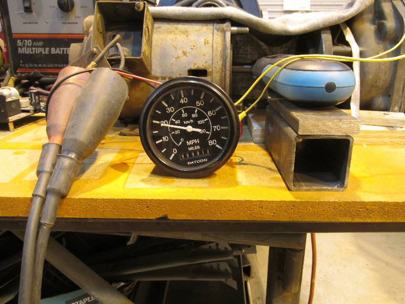
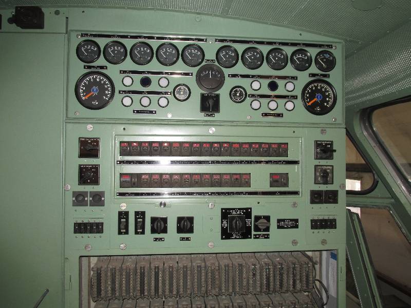
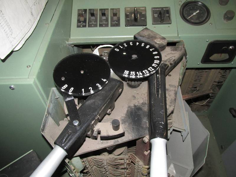
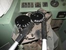
The locomotive was originally
equipped with a Barco repeating speedometer on the engineers desk.
It was long gone and no exact replacement could be found so
an
electronic unit was adapted. It was necessary to calibrate
the
unit to our speed sending units and the first 2 photos reflect this
process. The variac is providing fine control to the battery
charger which in turn is powering a 32 volt motor which is connected to
the GE axle drive. It was all a bit Rube Goldberg-ish but it
worked just fine. A low frequency pulse generator could be
used
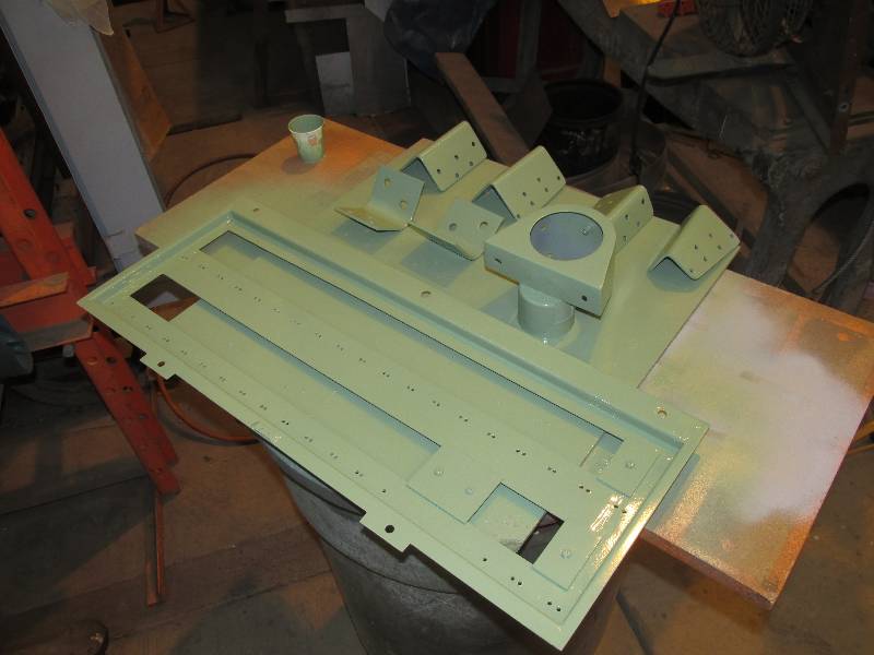
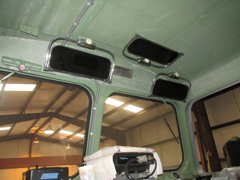
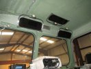
for the same purpose. Some bits and pieces were finally
painted
and Bob installed them in the cab along with the Happich sun visors (sourced by
Richard Oed in Germany) and the brand new position indicators made by
Seattle Engraving.
 |
 |
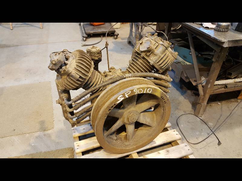
Two of the systems we still do not
have are a compressed air supply and a supply for the hydraulic system.
The parts for both are 100% missing thanks to the Camera Car
conversion in 1968. We are trying to maintain historic
accuracy on the visible aspects of the locomotive but for the air and
hydraulics, we are left to be creative. We actually only need
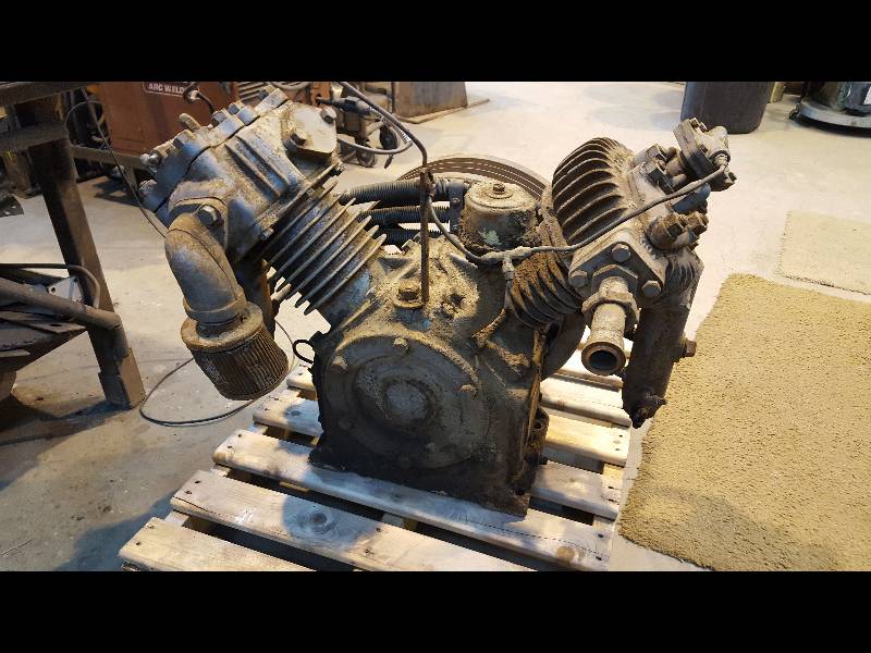
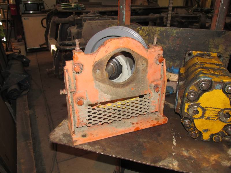
a compressor and the means to drive it for the air supply.
Thanks to our good friend Matt Monson of Diesel Motive, we
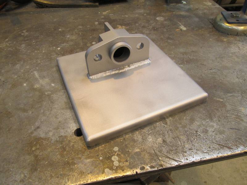
now have a locomotive style compressor. It is somewhat
smaller than the original unit but should suffice for the reasonably
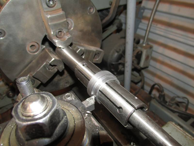
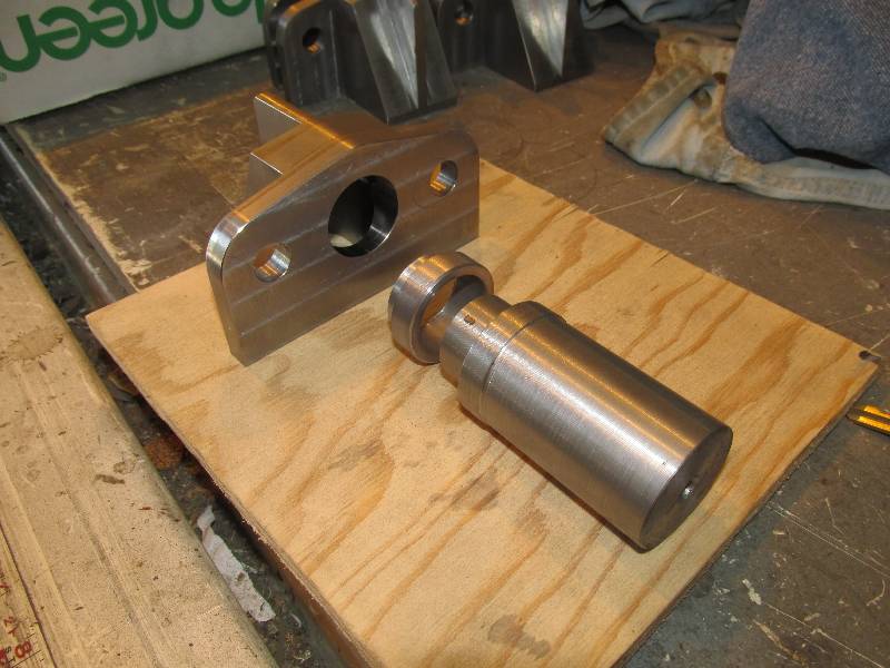
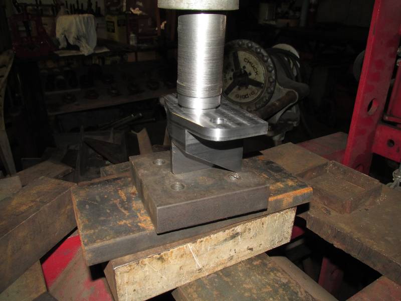
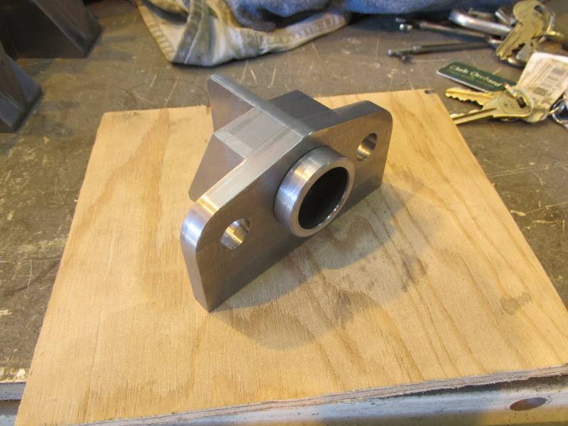
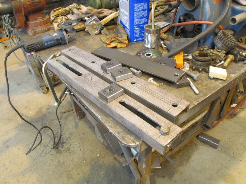
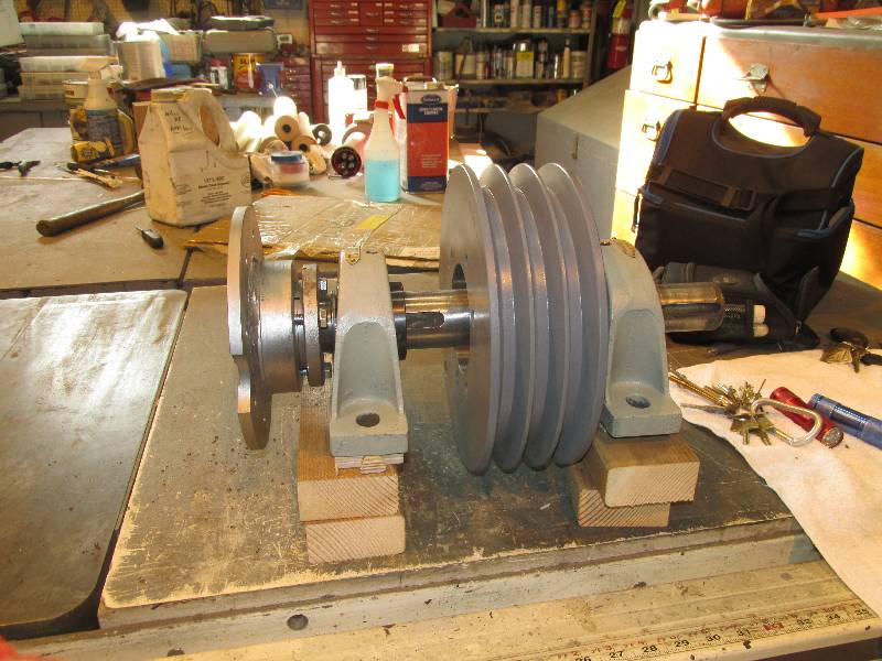
low demands of the 9010. The only complex part of this
project was the modification of some existing parts to create the
needed belt drive and coupling to the engine crankshaft.
 |
 |
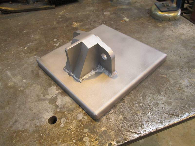
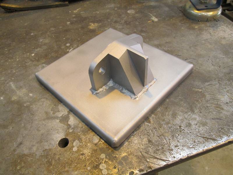
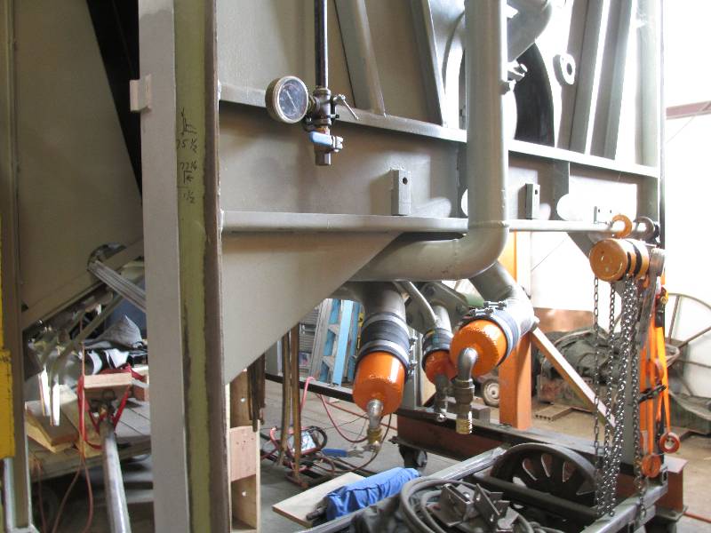
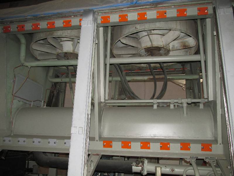
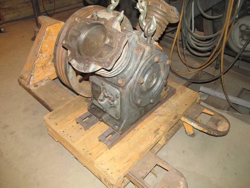
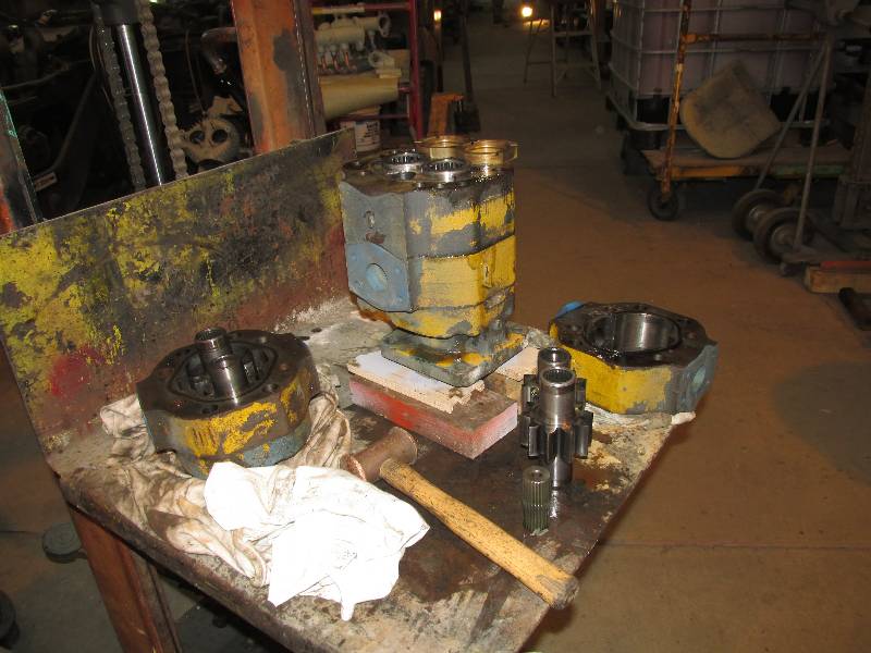
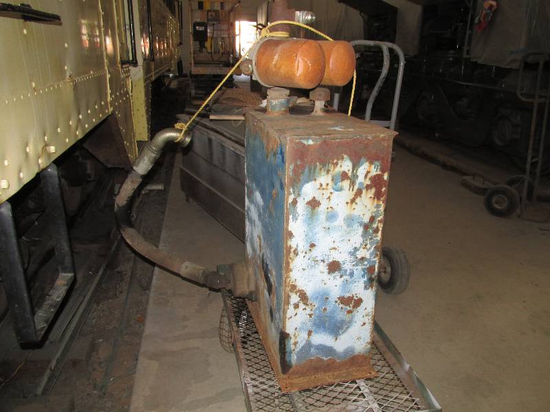
The hydraulic pump system is
somewhat more complex than the compressor installation. There
are two pumps because there are two separate cooling fan circuits and
we were given a pump from a piece of dirt moving equipment.
This pump had 3 sections so one was removed making the dual
pump we need. We also got parts including a pump mount and
oil tank from a piece of track maintenance equipment.
We also acquired a new volunteer.
Her name is Dee and she is an absolute terror with a needle
gun! She has taken on the task of cleaning all of the areas
behind the frame doors and re-installing the friction dampers.
There will be more about this as her work progresses.
Return
To Main Page
|