--
Update May 19, 2019 --
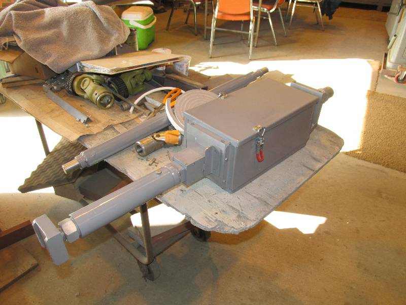
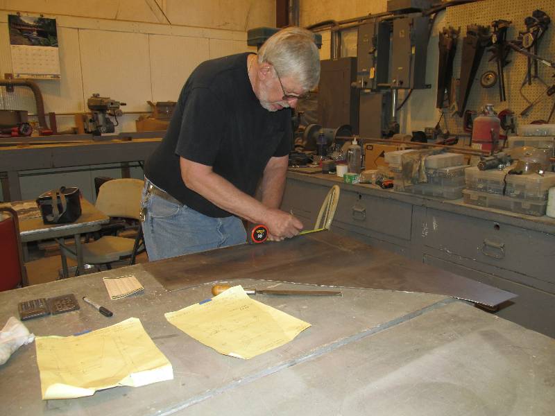
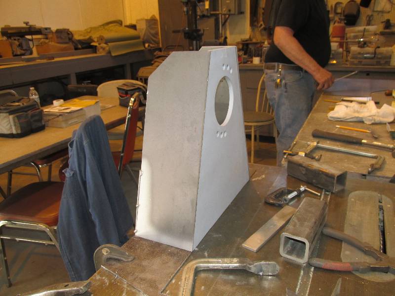
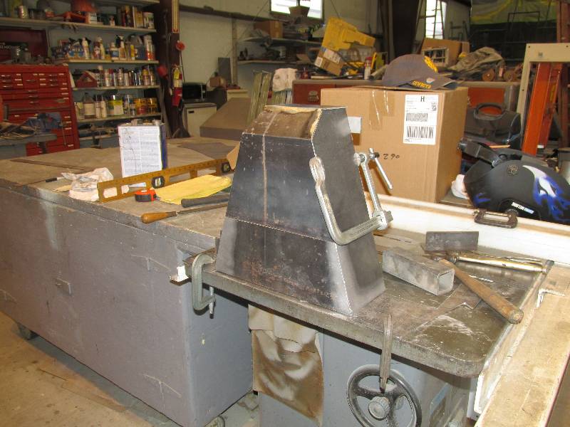
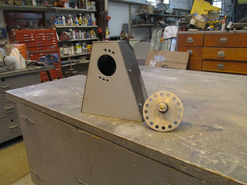
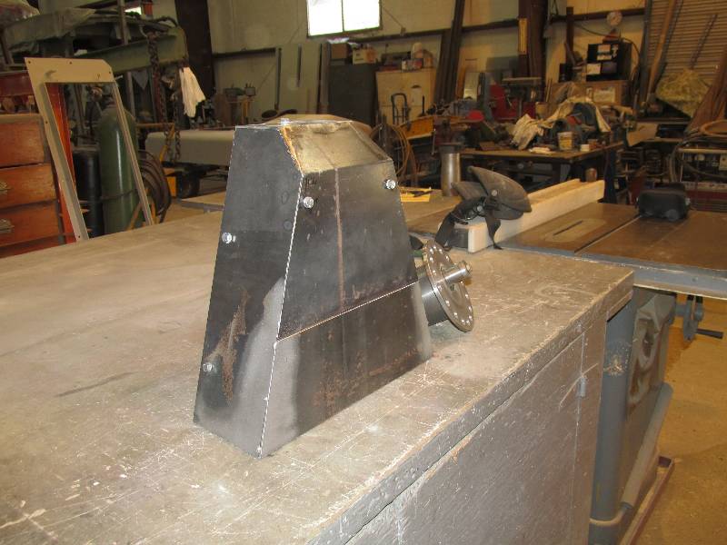
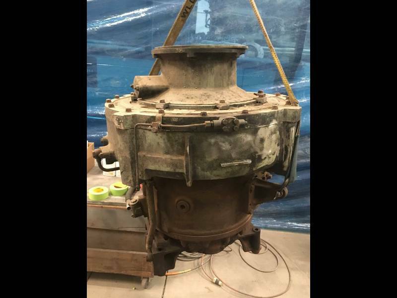
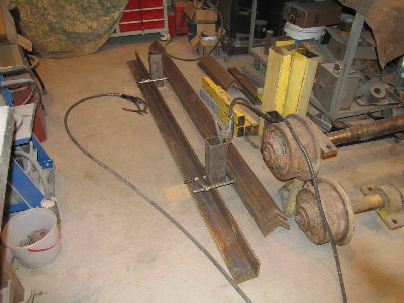
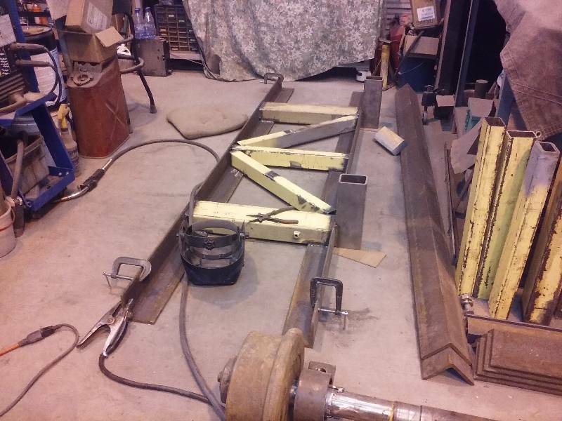
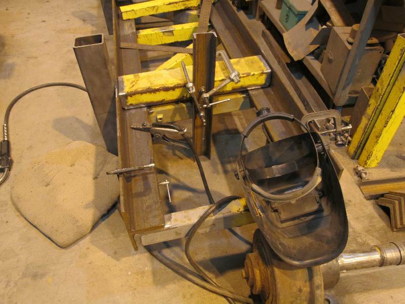
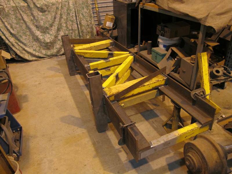
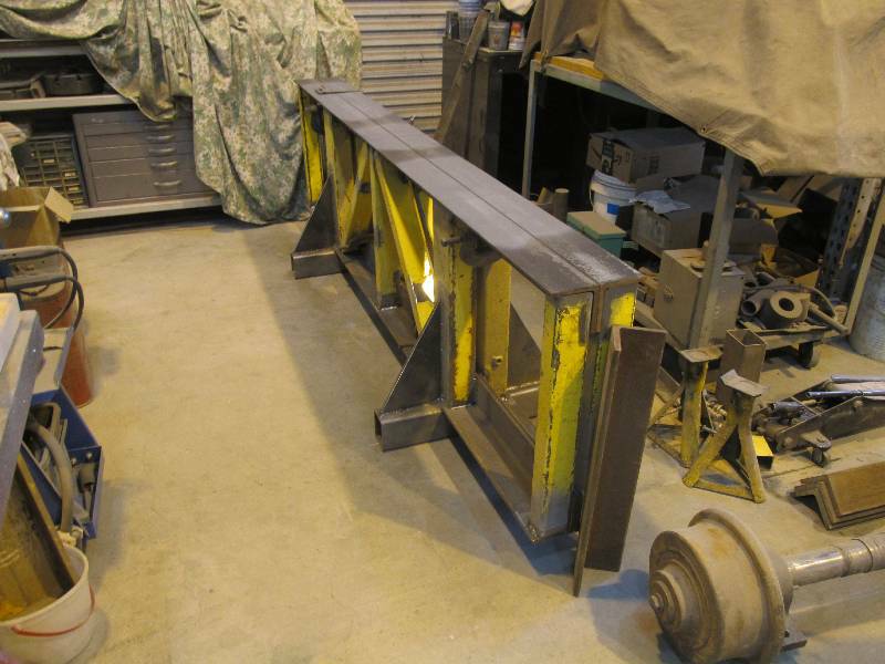
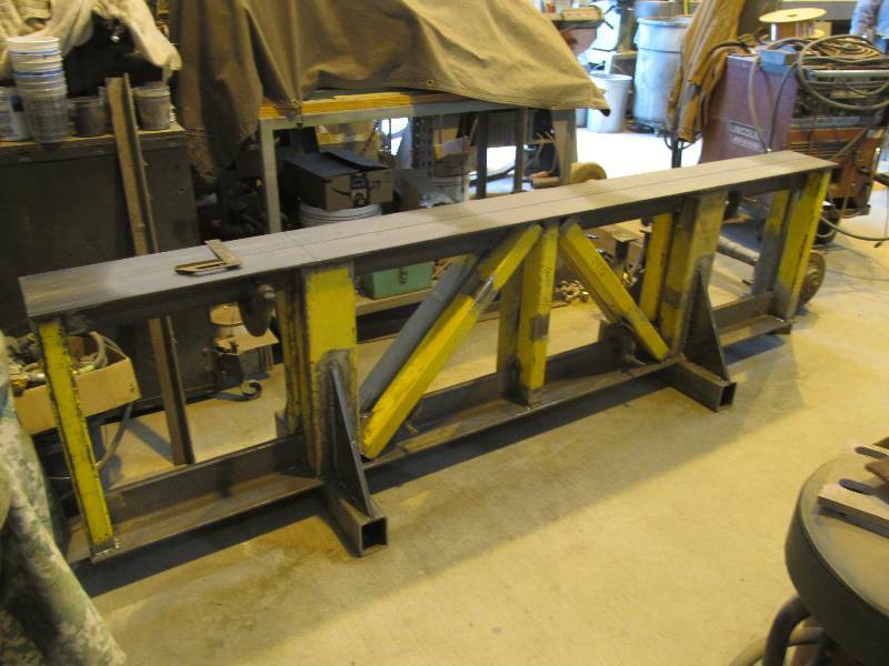
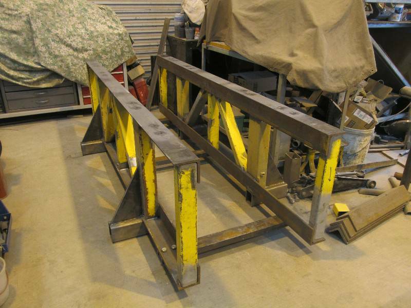
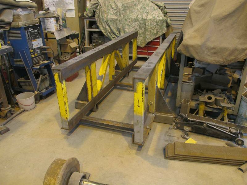
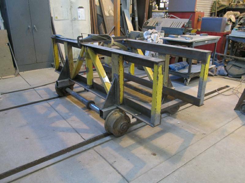
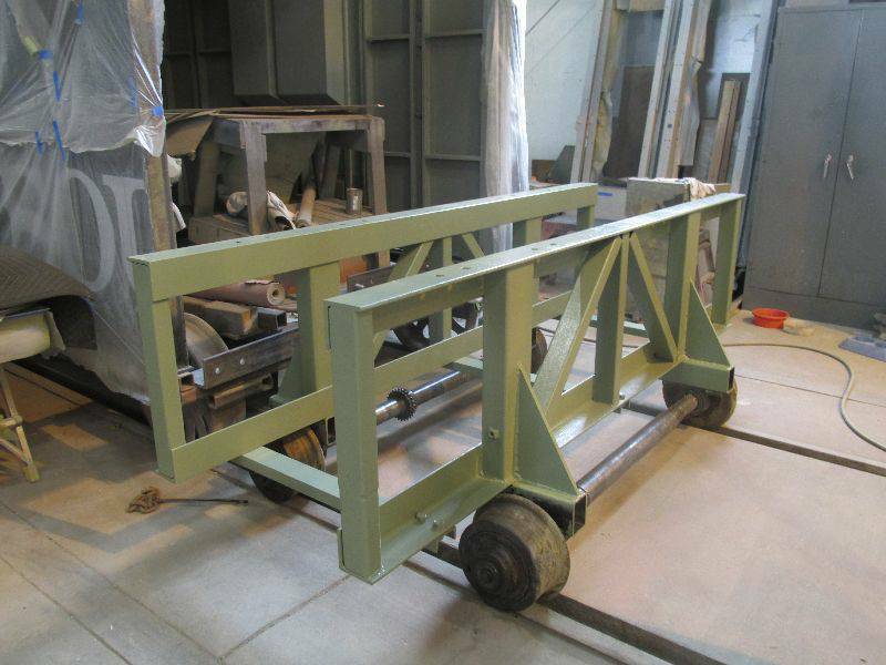
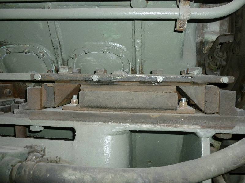
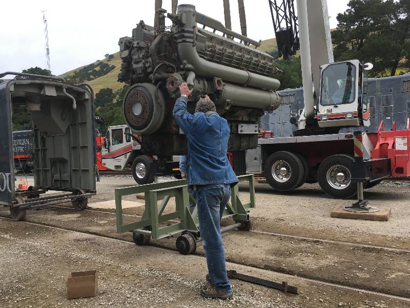
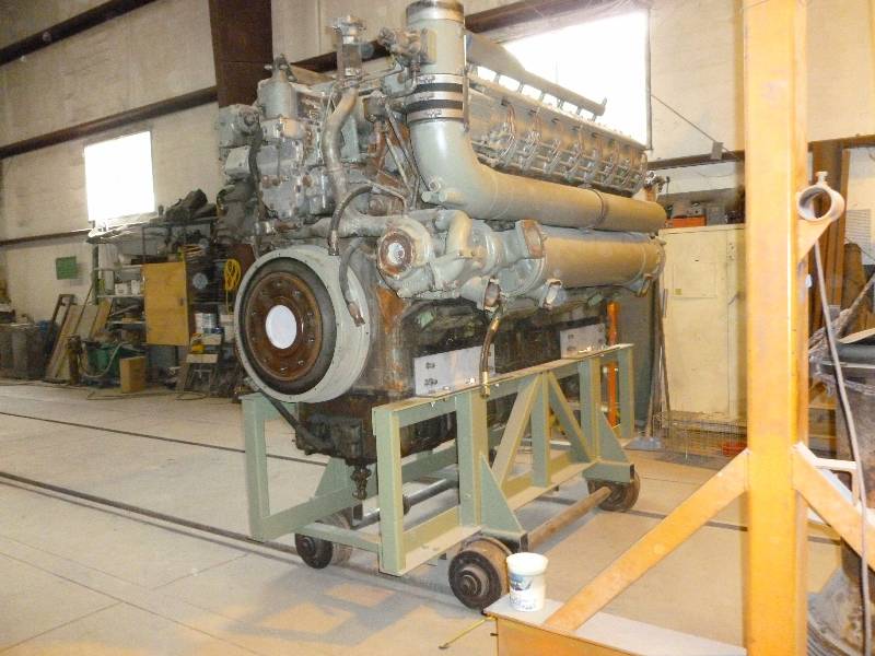
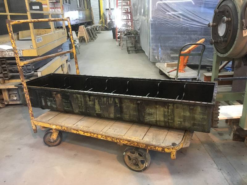
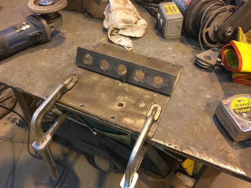
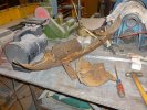
In preparation for removing the engine, we had to build a stand on
which to mount the 15,000 pound lump. In reality, it would
only weigh about 13,000 pounds due to the removal of the two turbos and
the two aftercoolers. With advice from our friends
in the United Kingdom, the Western
Locomotive Assoc. and the Diesel
Electric Preservation Group who have expertise in Maybach
engines and
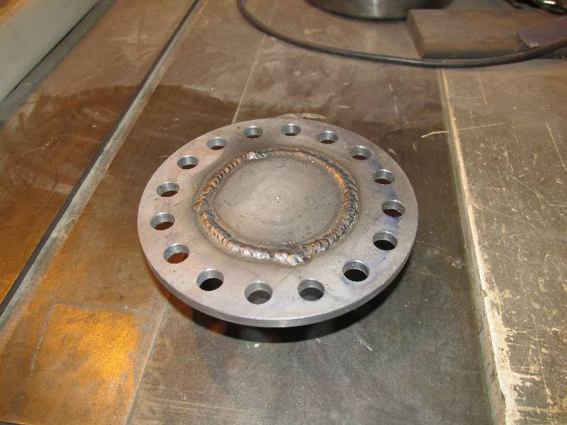
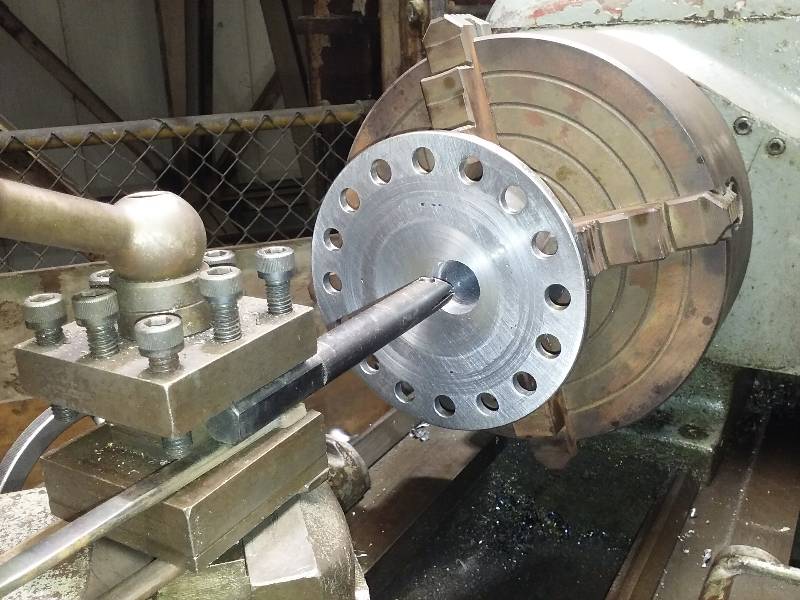
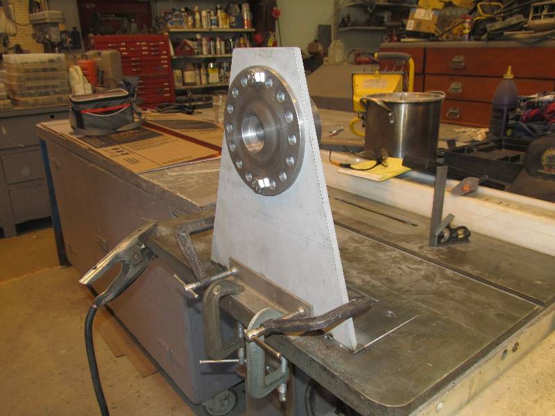
diesel hydraulic locomotives, we designed the stand using mostly
available scrap materials. It is mounted on a pair of flanged
wheeled axles rescued from a piece of maintenance-of-way equipment.
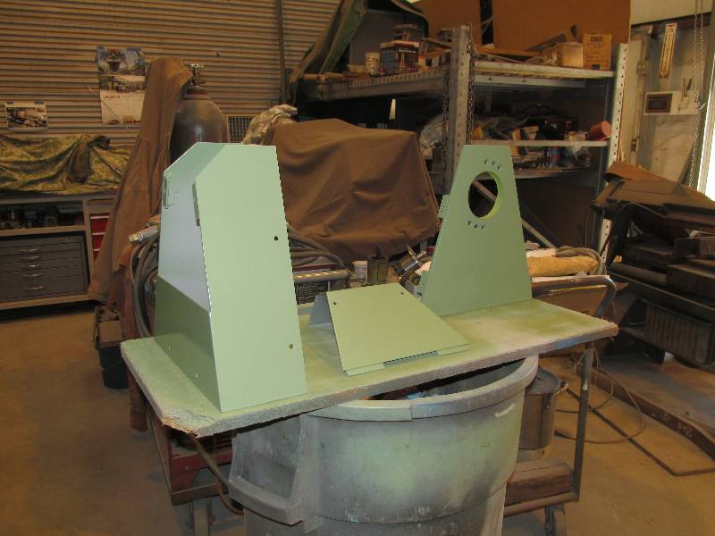
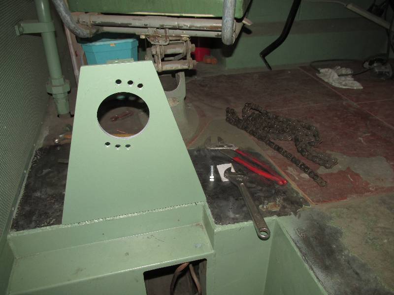
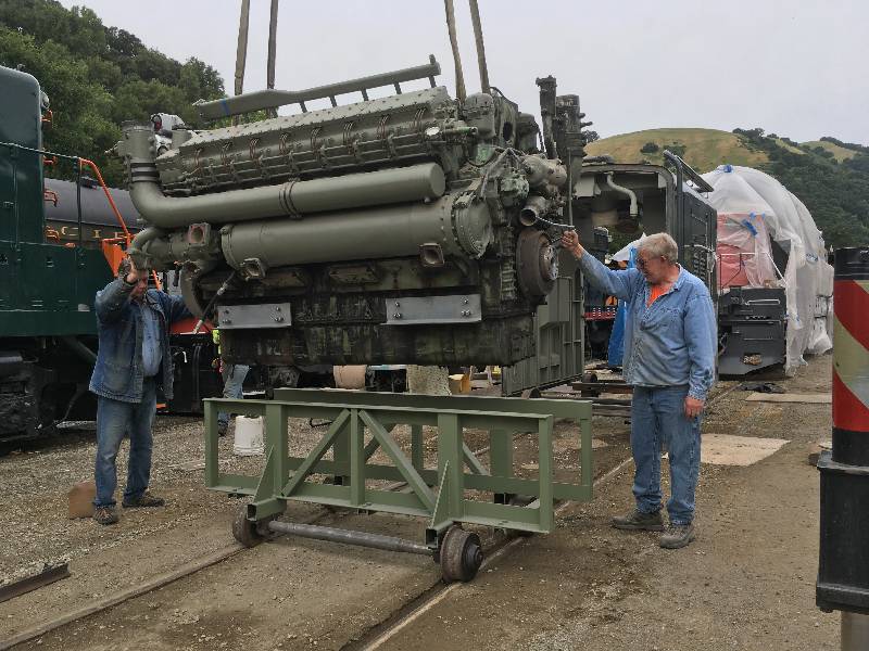
Once it was finished, Dee provided it with a good cleaning
and a coat of zinc oxide paint.
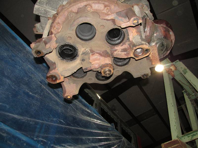
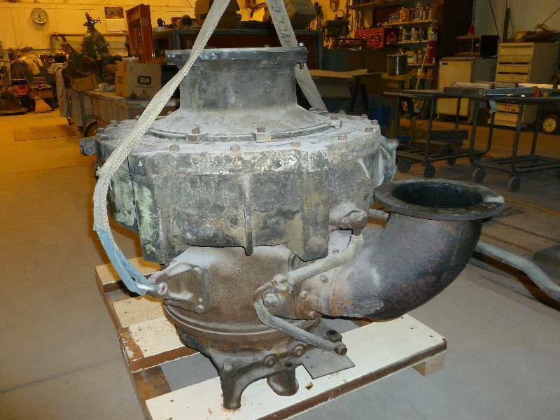
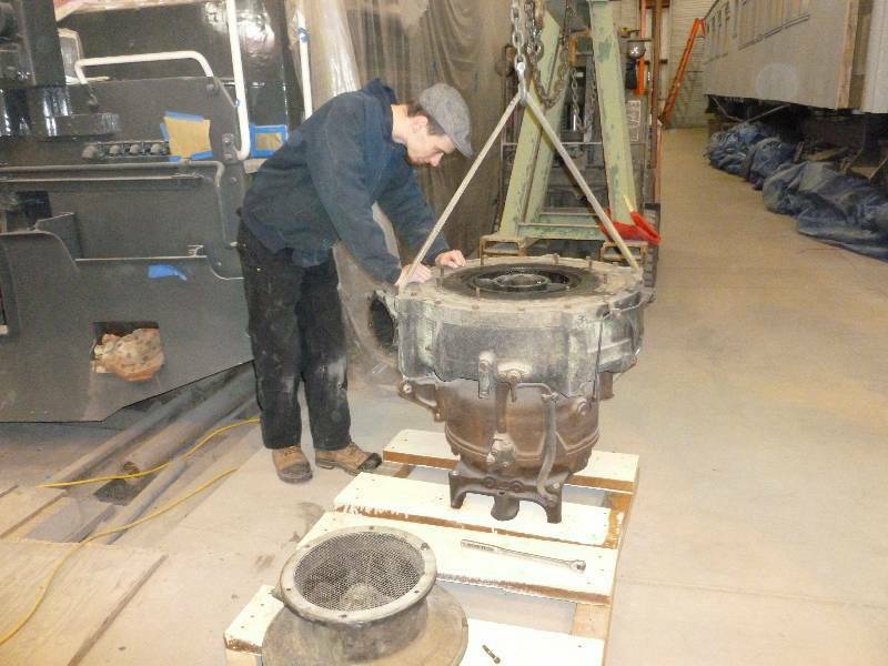
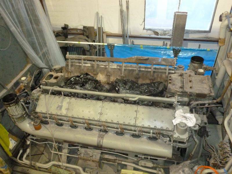
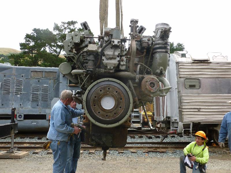
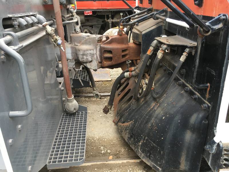
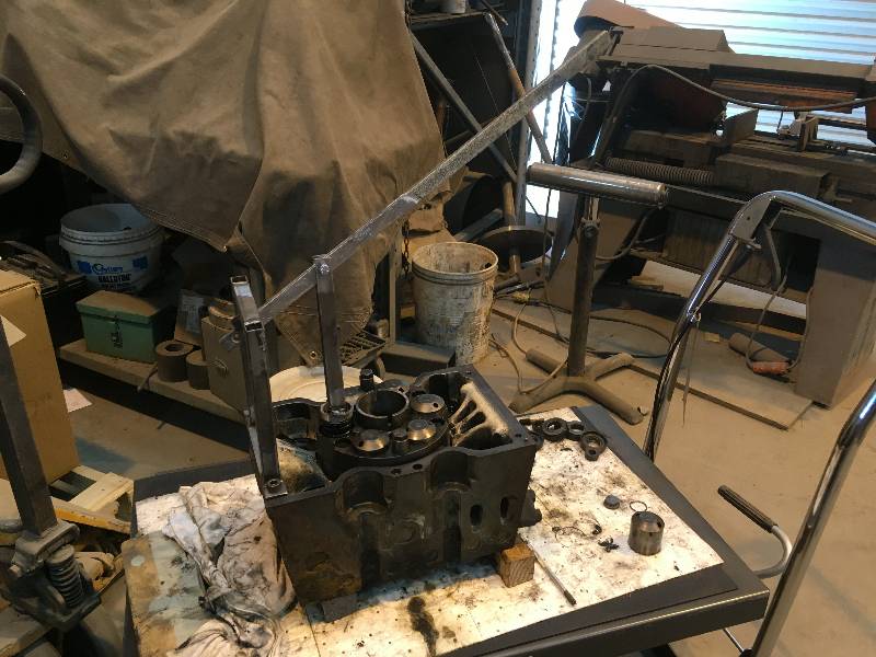
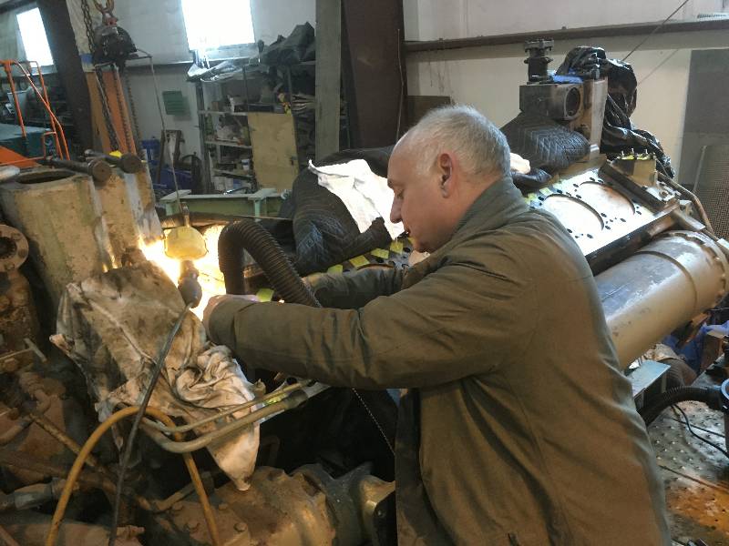
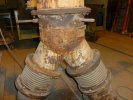
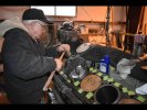
Before removing the
engine, we once again removed the turbochargers and bolted them to
stands that Dennis made. My grandson Matthew is taking a look
at the top bearing area of the front turbo. This is the one
that is pumping oil into the intake system, an issue that will have to
be rectified.
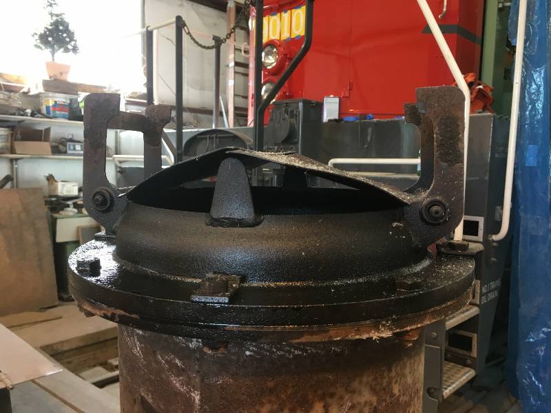
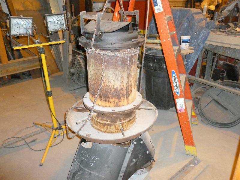
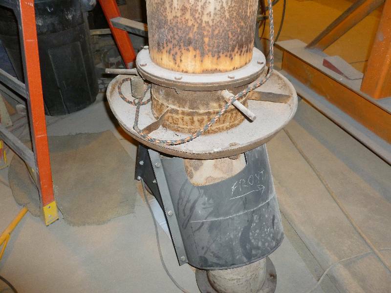
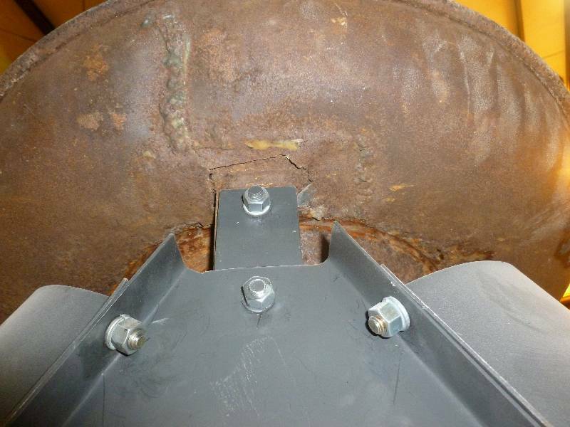
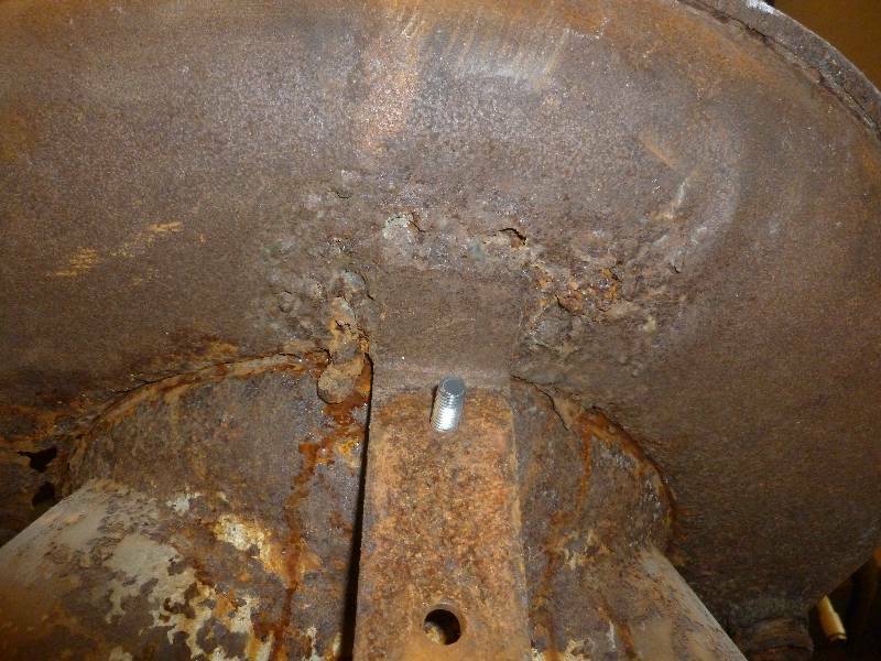
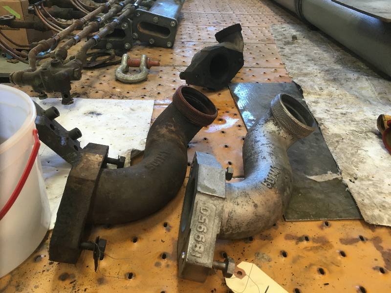
Another thing removed
was the exhaust outlet assembly. It has a "pan" around it
that is supposed to catch rain water coming through the exhaust stack
hole in the hood. There originally was a hose or pipe that
drained the pan but it was long gone. The pan itself is in
terrible shape being more rust and luck than actual metal. A
new pan will be fabricated before the stack is reinstalled.
 |
 |
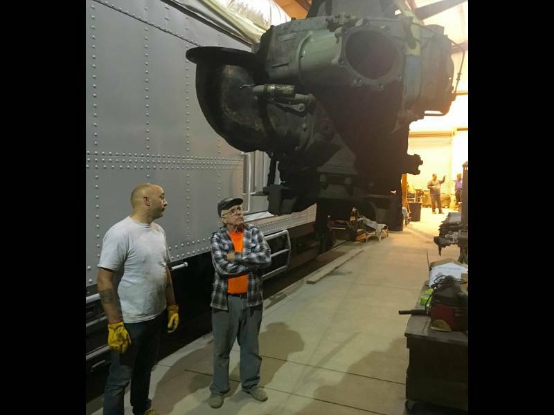
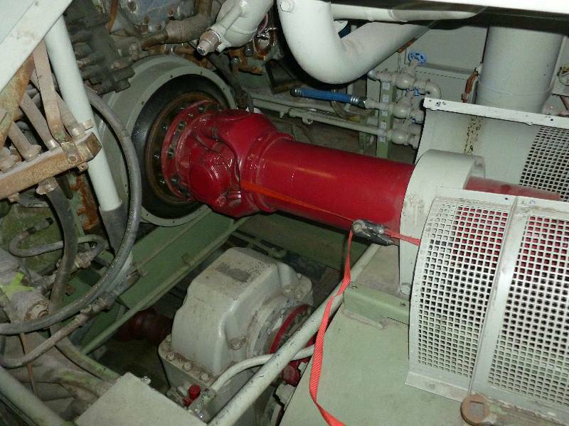
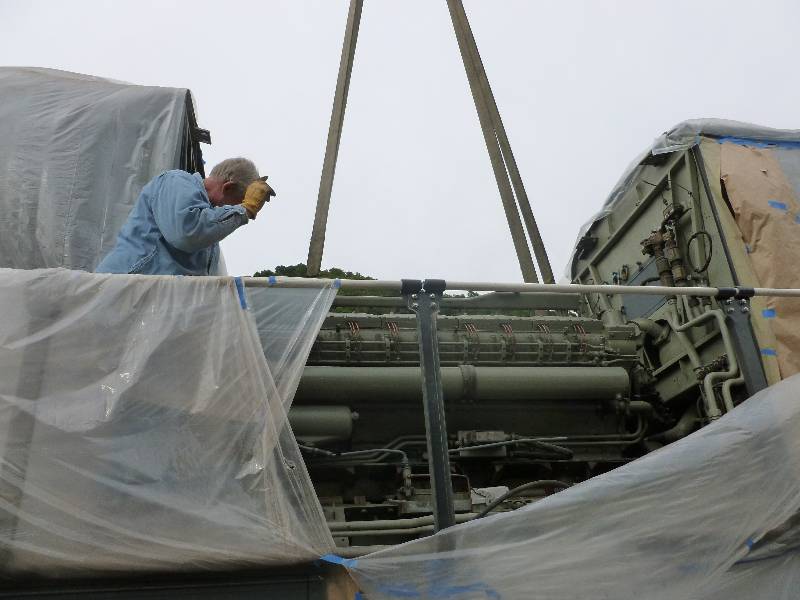
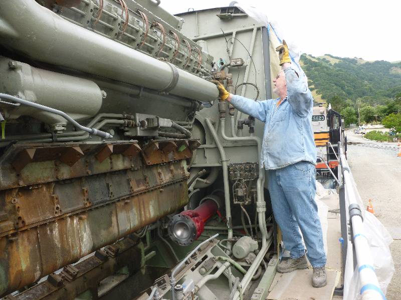
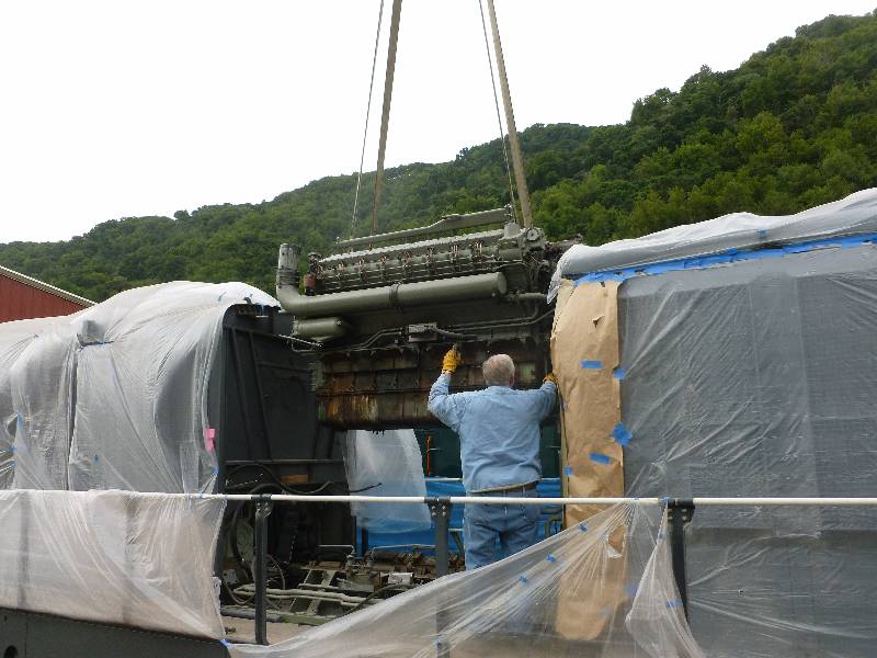
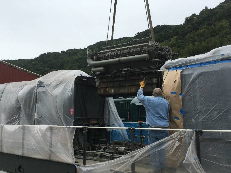
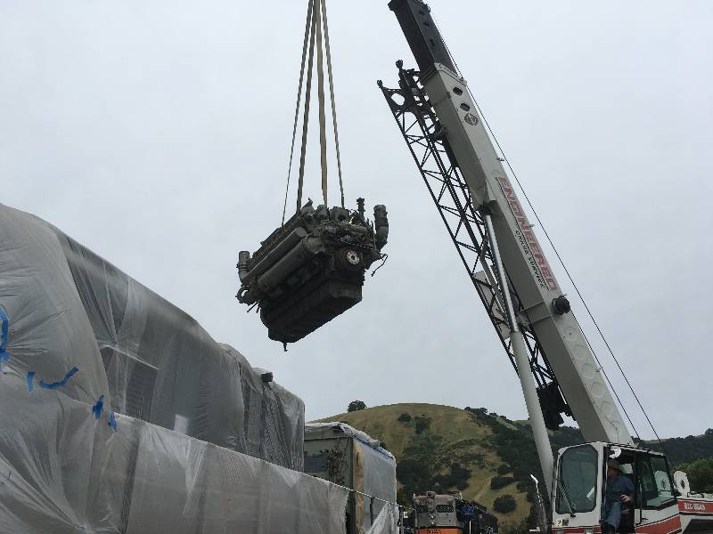
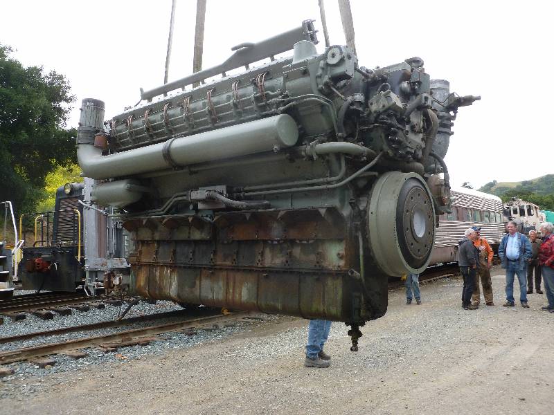
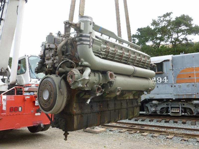
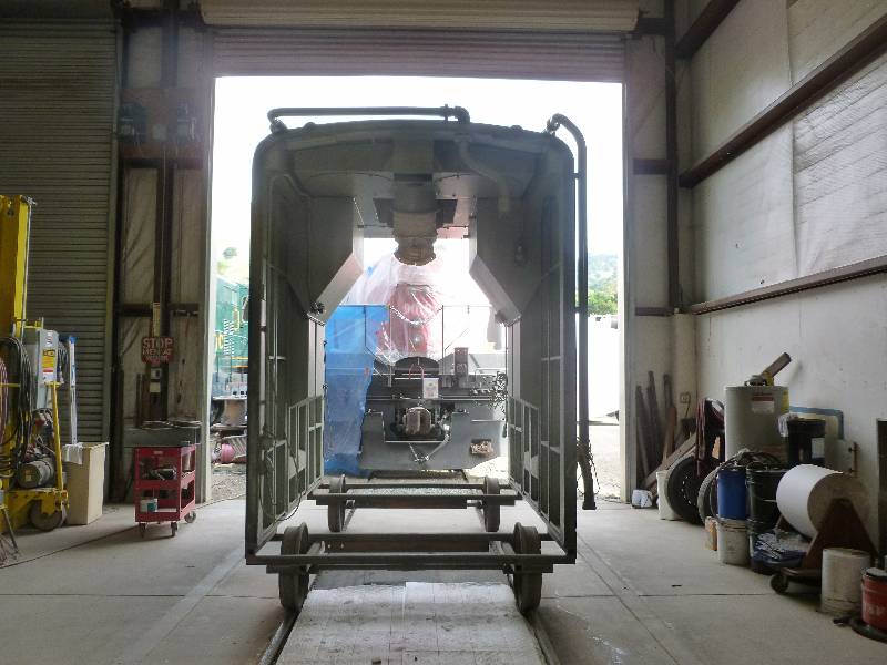
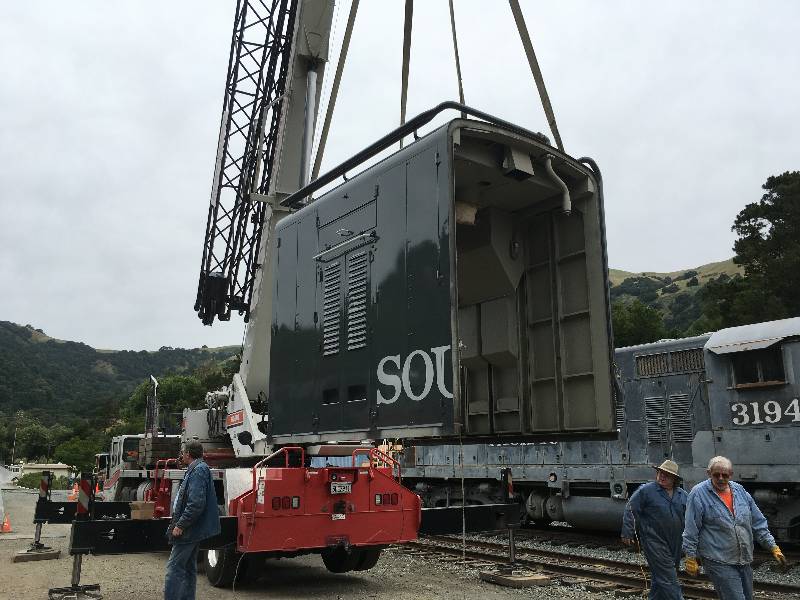
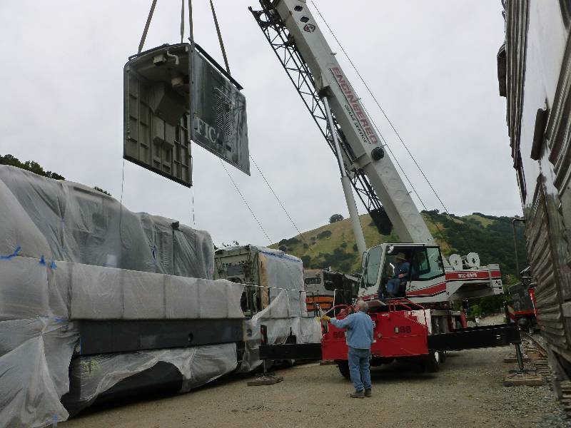
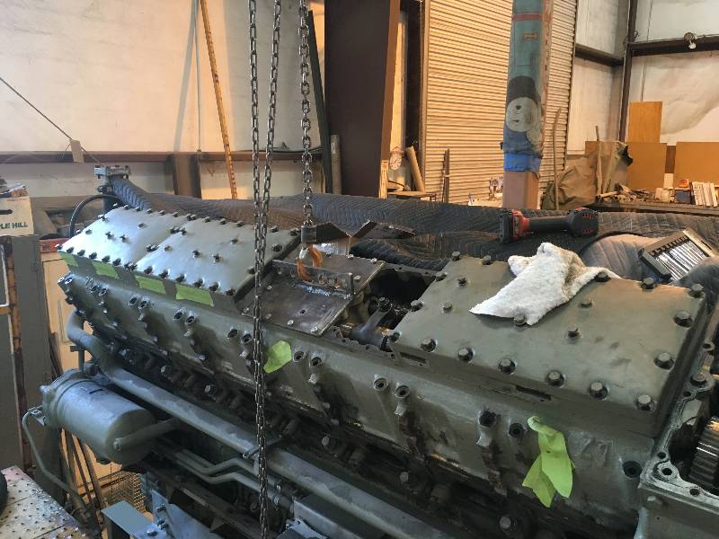
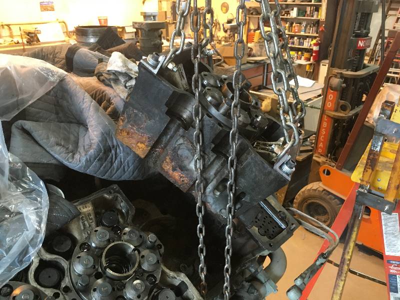
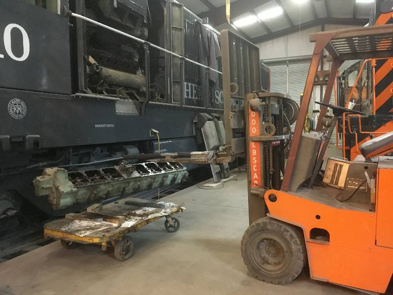
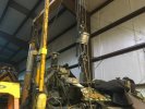
Dennis and I had been
spending time disconnecting motor mounts and other connections in
preparation for the big lift. And then came Saturday, May 18.
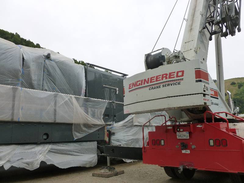
Ed, owner of Engineered Crane Services arrived promptly at
8am with his lovely 40ton hydraulic crane. By 8:30, we were
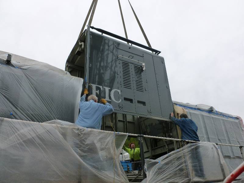
ready to do the lift. After a couple of trial pulls to
determine balance, the engine easily came out under the control of
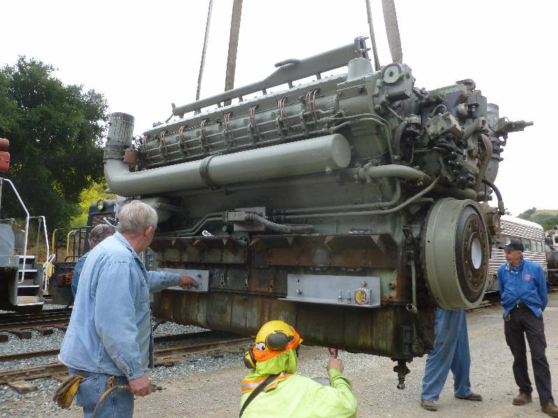
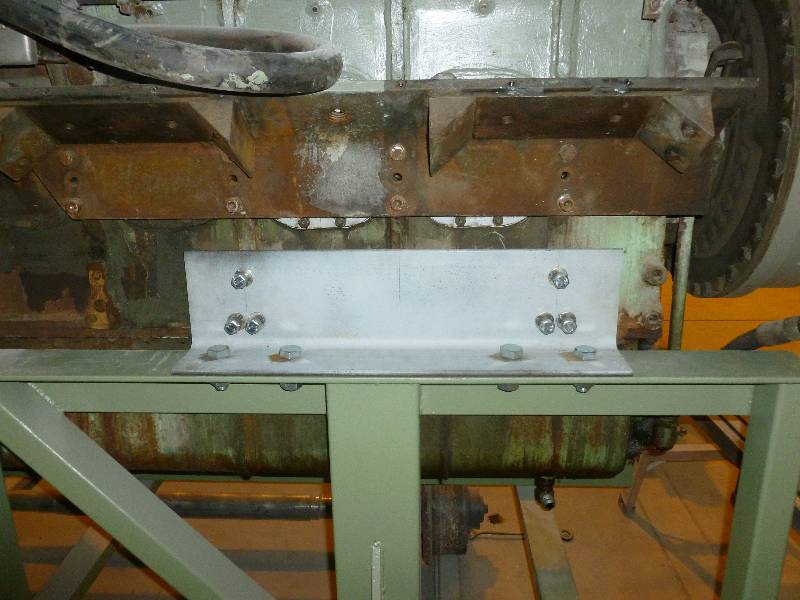
Bill's watchful eye. Ed positioned it so we could bolt the
engine mounting angle irons to the block and then Bill and Dennis set
it into the stand while Dee and I took photos. I was glad to
see
that the removal of the engine did not materially effect the coupler
height of the 9010.
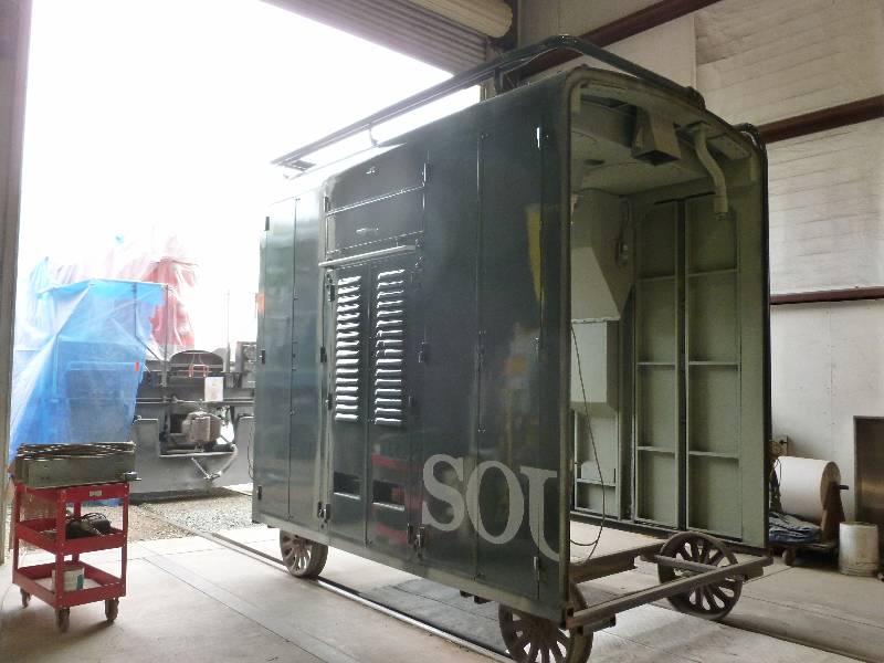
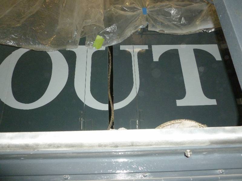
While the crane was
on site, we re-installed the number 2 engine hood. This marks
the first time since September 30, 2014 that the major bodywork on the
9010 has been complete.
I was relieved to see
that once the hood was in place, the lettering lined up properly.
--
Update March 29, 2020 --
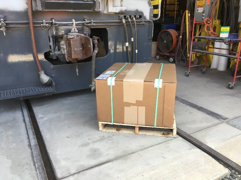
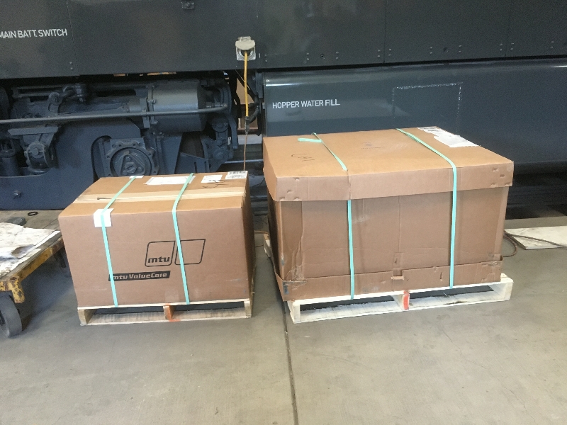
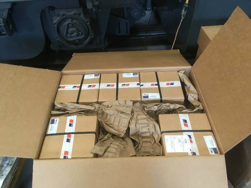
On the last day of May, 2019, we received a large crate of parts from
MTU. The crate contains piston rings, gaskets, rubber parts
and some very special tools. This was not all the parts we
would
require for the rebuild but we will not know what else we need until
the engine is disassembled and we could see what was worn out or
defective.
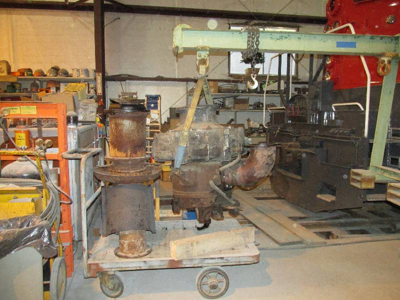
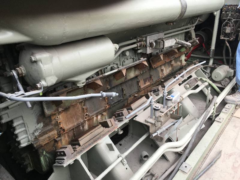
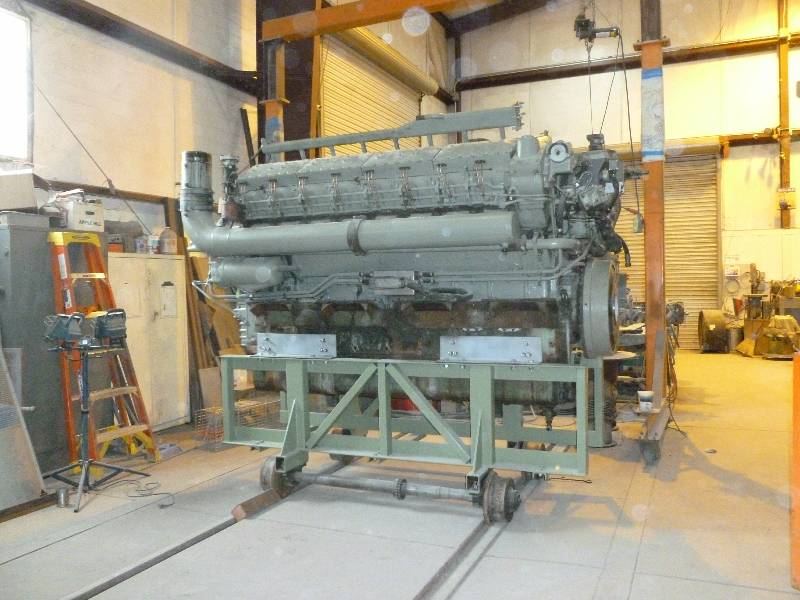
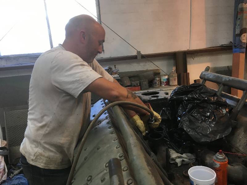
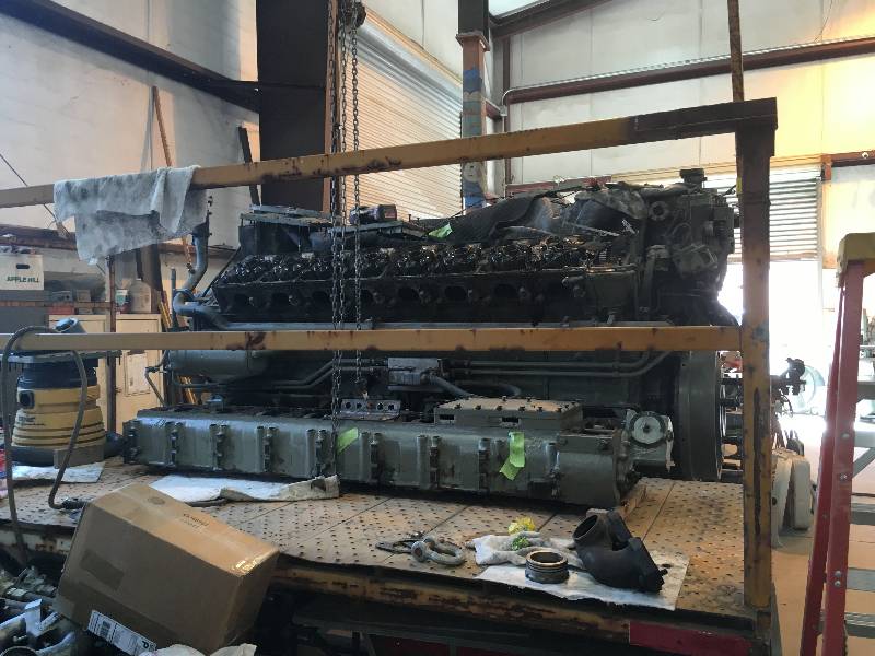
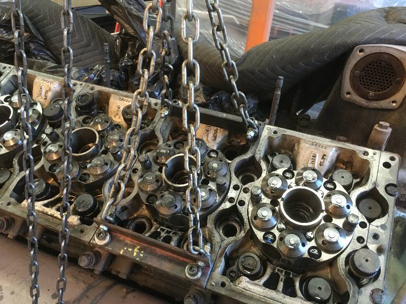
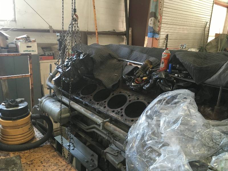
Shortly after the
engine was relocated to the shop floor, we began its disassembly.
Rob started removing the exhaust elbows. These
connect
each head's exhaust port to the turbochargers through connections in
the bottom of the turbos. There are only 12 of these as 4
heads on each side share elbows. Dee soon went to work bead
blasting them.
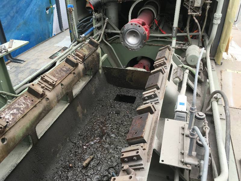
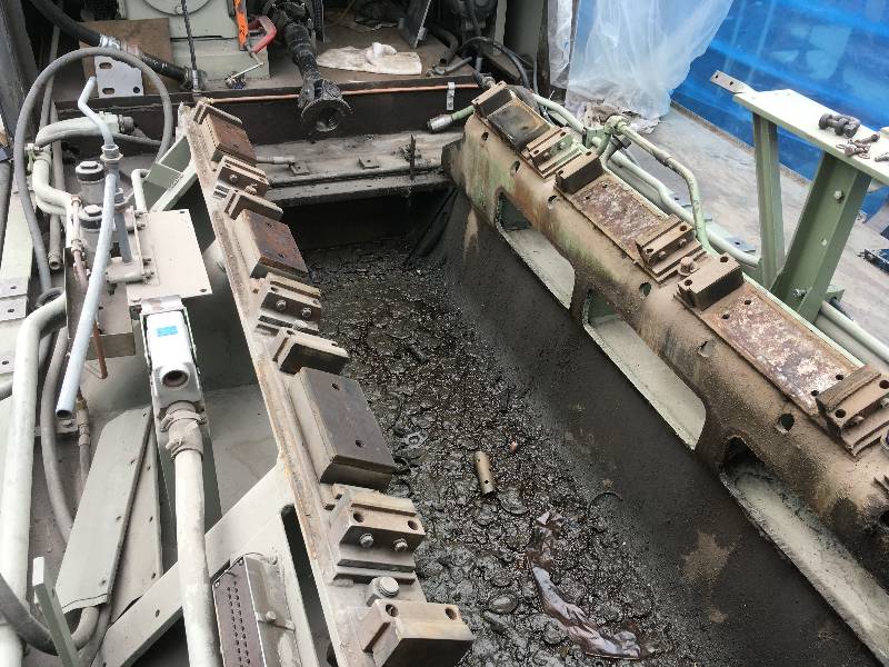
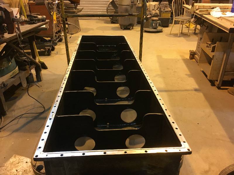
We removed the oil pan in order to eventually get at the connecting rod
bolts. There are about 100 small studs holding the pan onto
the bock. This was our first view of the underside of the
engine. Within a few days, Dee had cleaned the inside of the
pan.
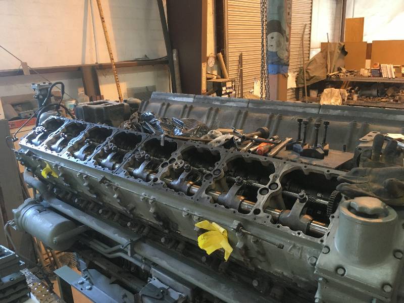
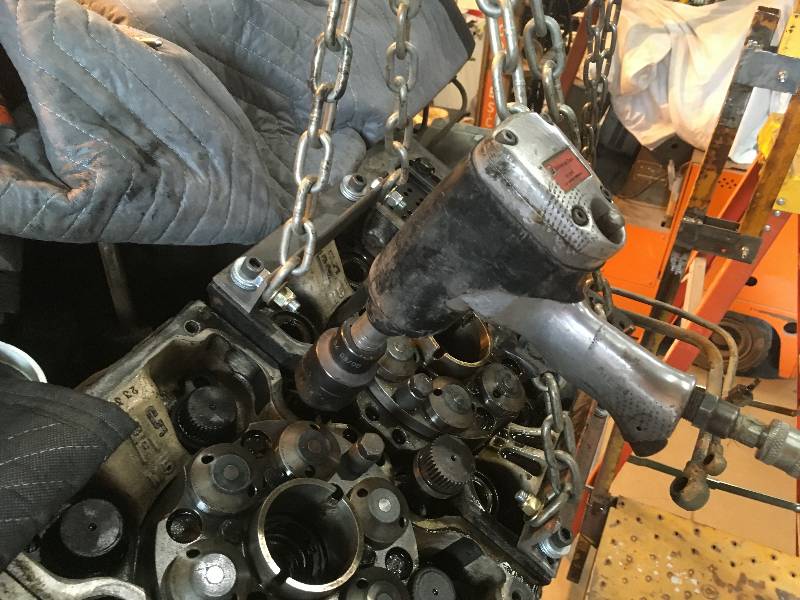
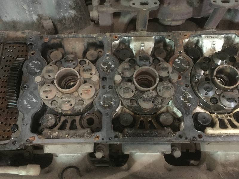
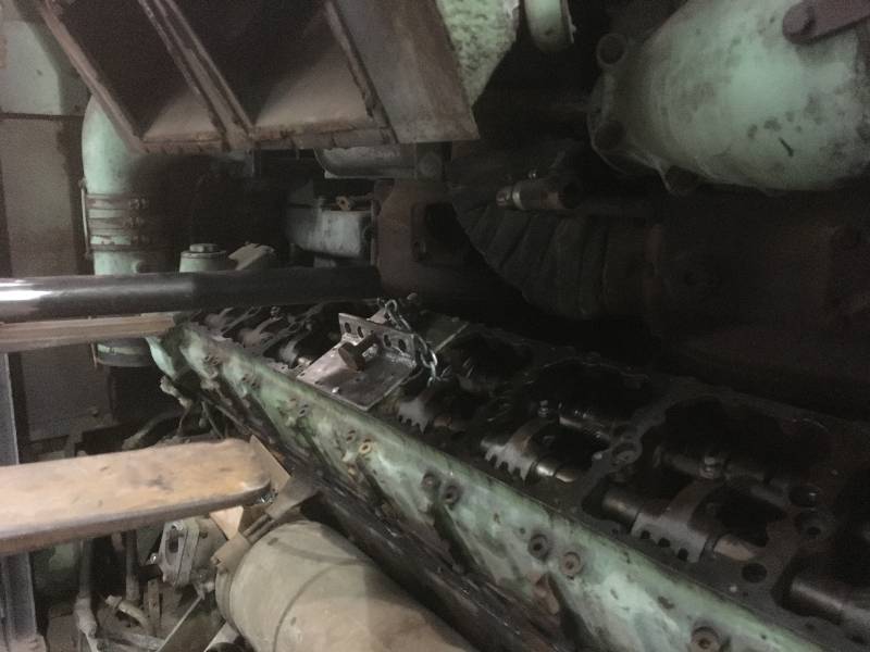
Back on top, work
started to remove the cam boxes. They are very heavy and are
held down to the heads with over 40 bolts. A special fixture
had to be fabricated in order to hold the assembly at a 30 degree angle.
With the cam boxes
removed,
we had access to the head bolts which are serrated and require a
special tool from MTU.
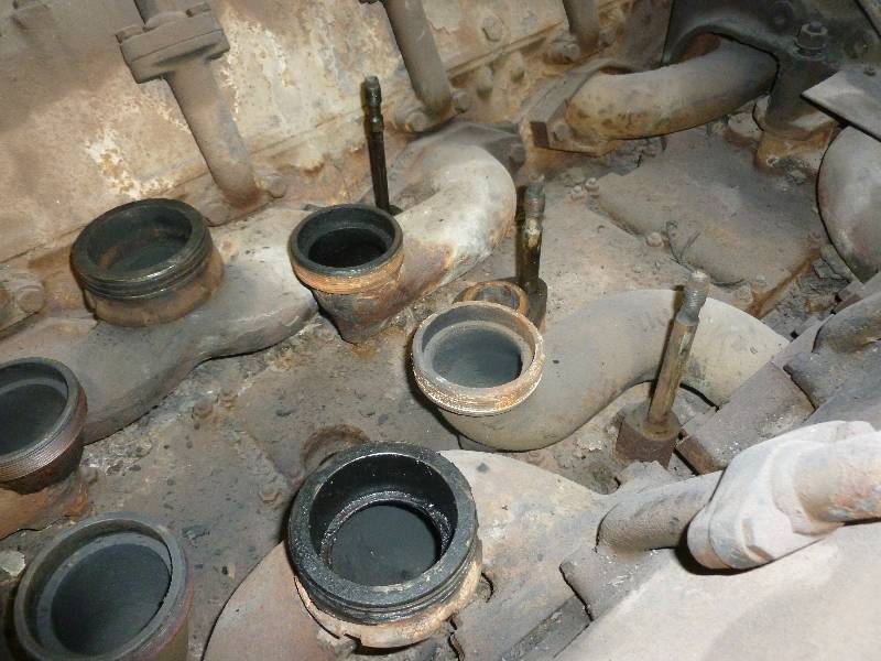
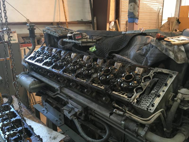
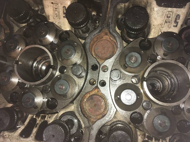
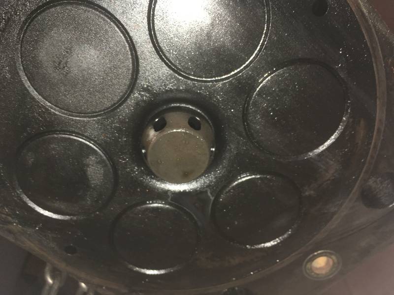
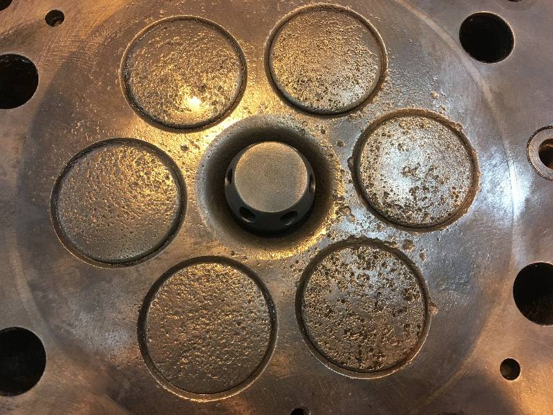
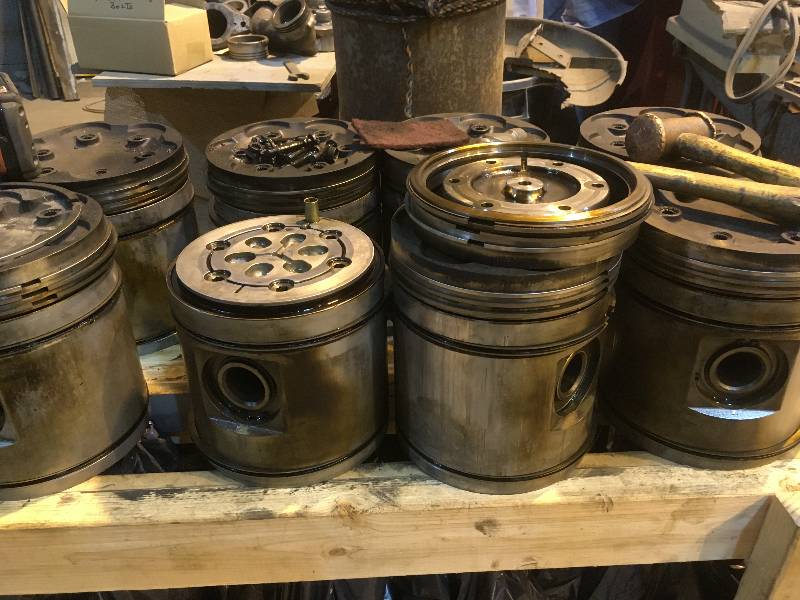
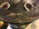
Once the heads
started coming off, we had our first view of the tops (crowns) of the
pistons. The one in the second photo shows the results of a
worn out furnace.
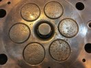
Each cylinder head
has a "furnace". Initial combustion does not take place
within the cylinder but rather in an area above the furnace.
The flame then travels out of holes in the furnace and
propagates over the top of the piston. The furnaces are made
of a chrome-moly steel that is very hard, but over heating can cause
its flame ports to wear. Once worn, combustion becomes
inefficient which leads to problems like knocking, smoking and general
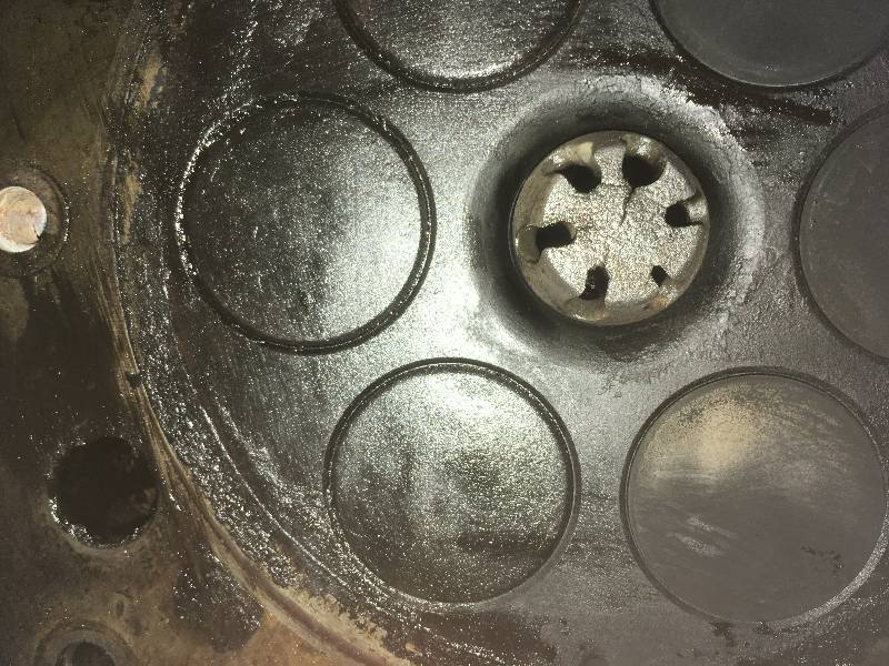
loss of power. Photo #1 illustrates a good furnace while the
others in this set show some of the 6 worn burners we found on this
engine. Evidently, overheating was a chronic problem.
Bill fabricated a
complete set of burner removal tools thanks to some parts sent from the
UK by one of our team but we were unable to remove any of the worn
burners.
We also discovered
that several cylinders had suffered from water seeping in through the
exhaust valves. The valves and valve seats on this head are
destroyed as is the surface of the piston crown. Both the
head and the crown will have to be replaced. I had resisted
the idea of taking any parts from the #1 engine but the condition of
this head and the need for burners convinced us otherwise.
 |
 |
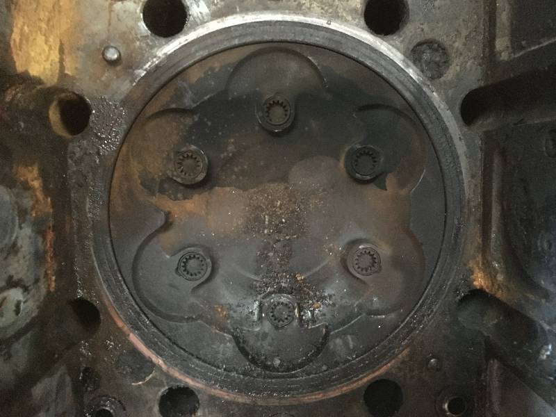
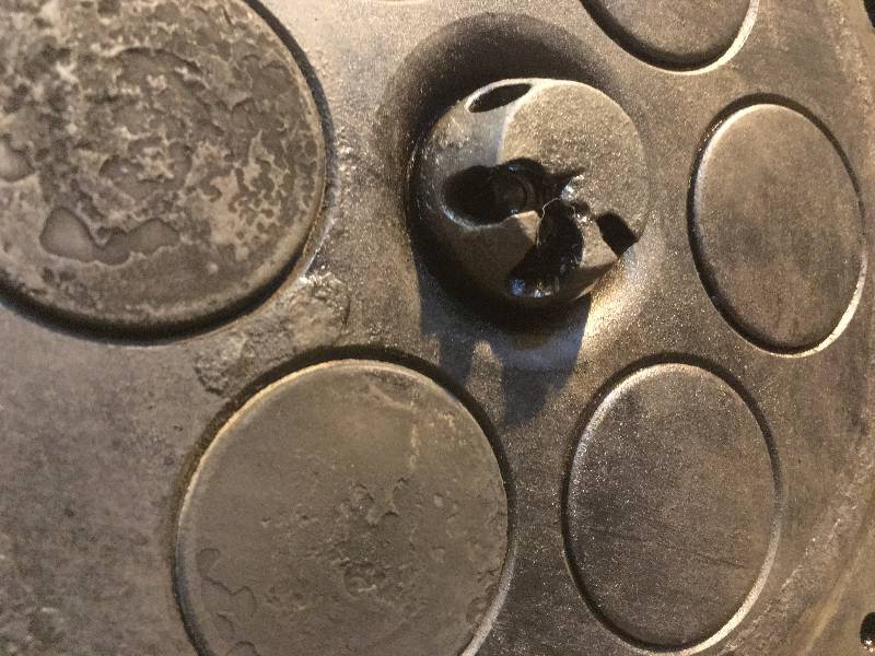
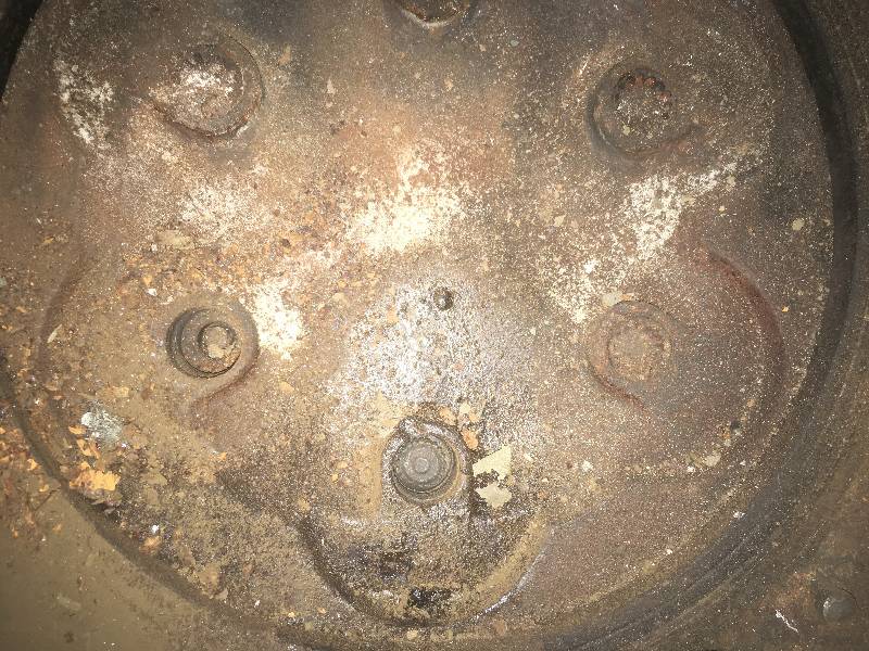
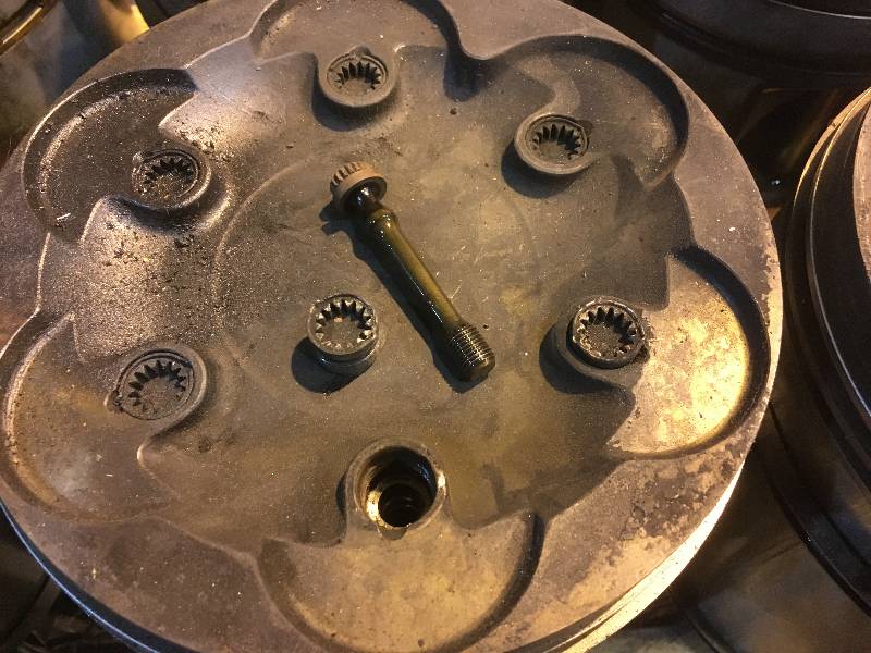
According the service
records, the 9010 was put out of service because of a failure in the
number 9 cylinder of #1 engine. There is no record of what
the failure actually was. The left bank of #1 was taken apart
so that the #9 head could be removed but was then simply thrown back
together leaving most of the bolts and all of the injectors in the
trash bin. We know that we needed 7 heads for the good engine (6
because of bad burners and 1 because of water damage). When
we removed the heads from the left bank of #1 engine, amazingly we
found that we had all 8 heads with good burners but head #9 looked
suspicious. Photo #2 is the crown of piston #9.
Note that it has two missing crown bolt caps and one broken
bolt. Note also that it is extremely clean with no sign of
carbon at all. This made me wonder if there was not a crack
in the cylinder head and thus caused us to reject this head for reuse.
While in that engine, I removed 4 crowns as we had several
bad ones on engine #1. One crown gave us quie a surprise with
a completely shattered top compression ring.
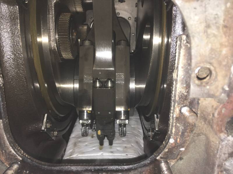
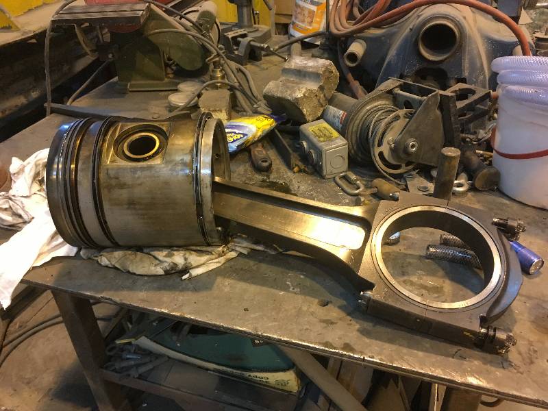
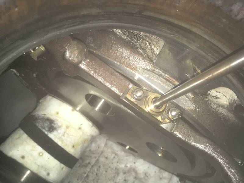
Next to come out of
engine #2 were
the pistons and rods. This engine has what are called "fork
and blade" rods. Most internal combustion engines have the
connecting rod bearings sitting side by side on the crankshaft
journals. This requires that the cylinders be slightly
staggered and thus increases the overall length of the engine block.
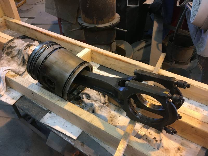
Fork and blade engines like the Maybach (and EMD's) use a
different system whereby the rods from opposing banks connect to the
crankshaft in the same space. Photos #1 shows the two rods in
place on a common crankshaft journal. Photo #2 is of a blade
rod and photo #3 is of a fork rod. The blade rod mounts
within the open space in the fork rod and thus makes for a more compact
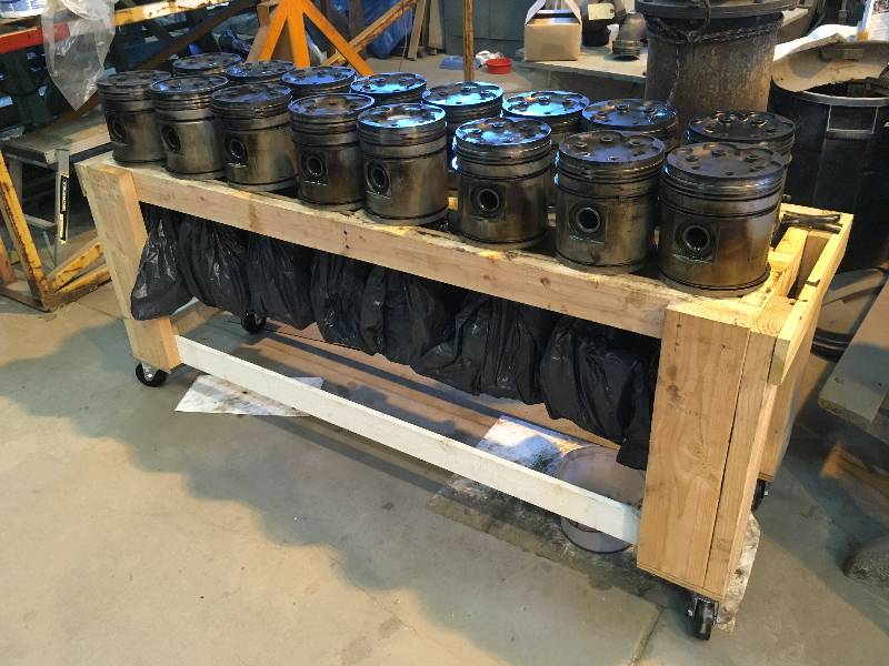
engine block. Eventually, they were all removed and stored on
a specially built rack.
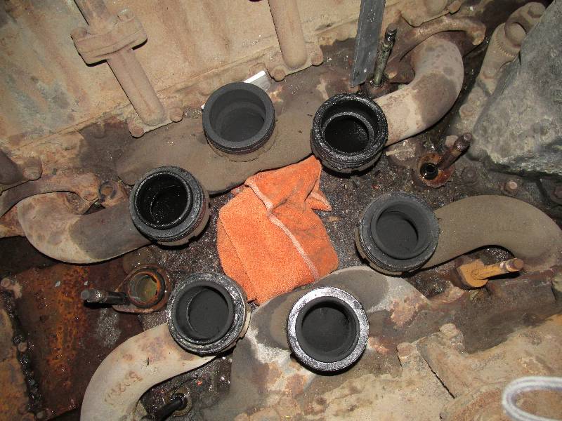
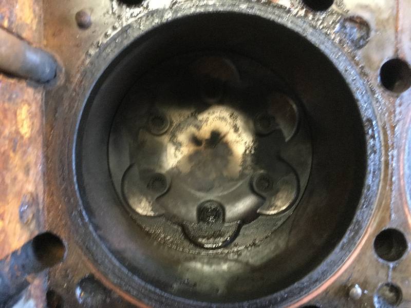
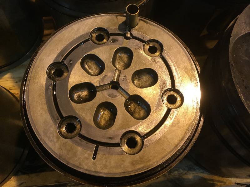
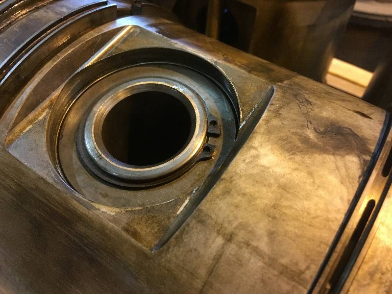
The top of the piston
is called the "crown" and on this engine is removable. The
crown contains all of the compression rings while the oil control rings
are mounted on the piston, one above and one below the pin.
The crown is attached to the top of the piston with serrated
bolts which are in turn covered by caps. Of course, both the
caps and the crown bolts require special tools. Removal of
the crown reveals the crown oil cooling passages. The small
tube seen at the top of photo #3 is the top end of the tube in which
the cooling pipe rides. The lower part of the cooling pipe is
shown in photos #4 and #5.
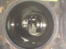 |
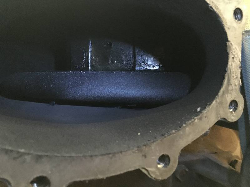
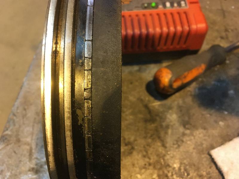
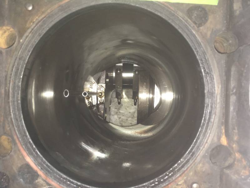
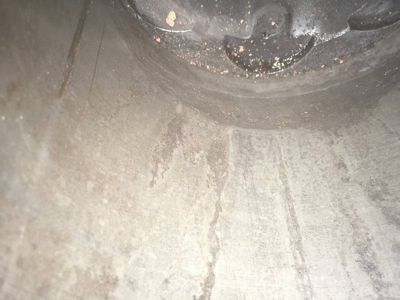
Having the pistons
out of the cylinders means that we could see the condition of the
liners. Ultimately, we found 5 liners that had sufficient
problems to make their replacement necessary. The one seen in
photo #1 shows the result of having water standing above the piston for
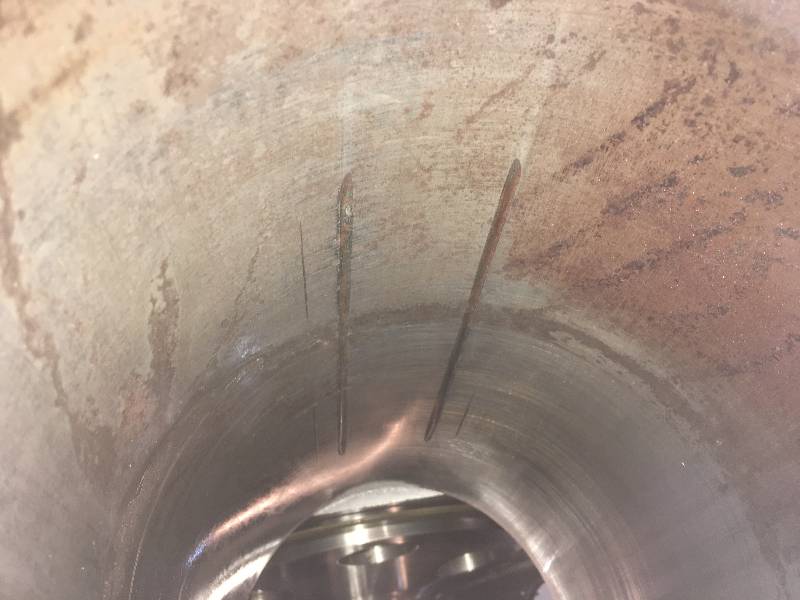
a very long time. The liner in photo #2 belongs to the
cylinder head and
piston crown shown above. Notice the two long deep scratch
marks in the liner. They were caused by the piston pin being
loose and digging into the liner wall. One of the two snap
rings that hold the pin in the piston was missing. This liner
also exhibits the corrosion caused by water standing in the
cylinder.
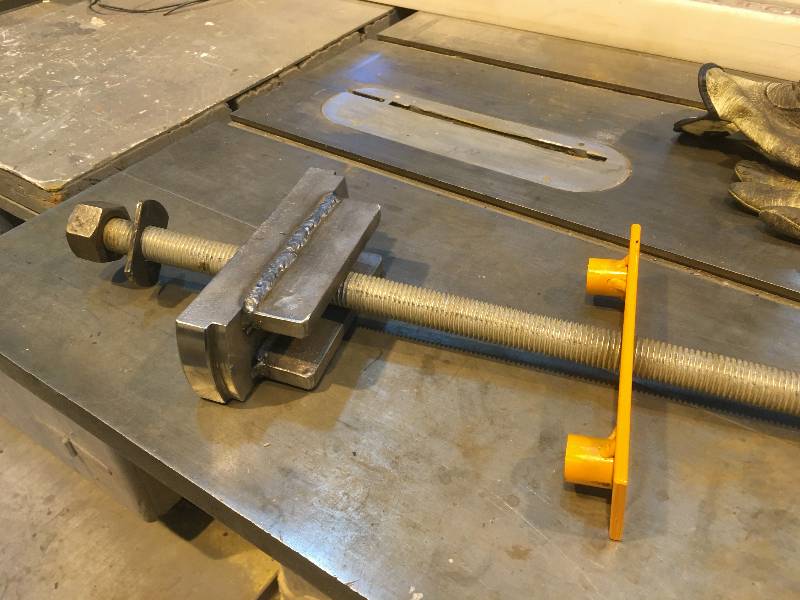
Dealing with the
heads took nearly 2 months. All valves were removed
(using our custom valve spring compressor),
the heads cleaned and tapped holes cleaned out. All valves
and seats were hand lapped.
The 7
rejected heads were all put
back on engine #1 and that side of the block was closed up.
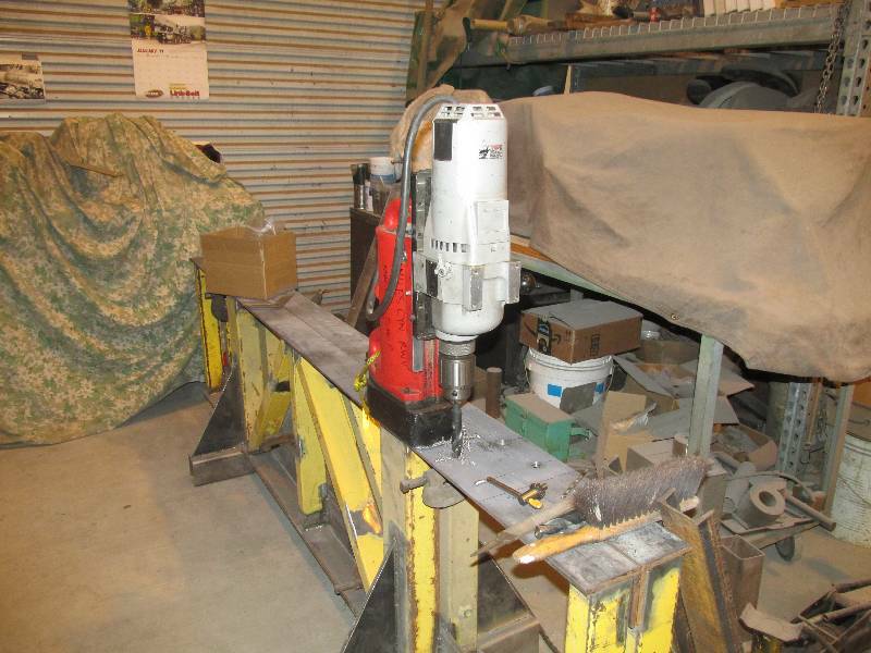
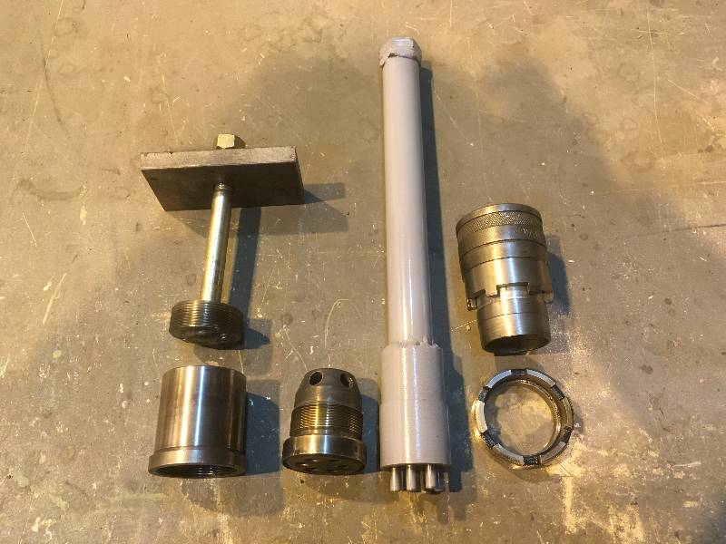
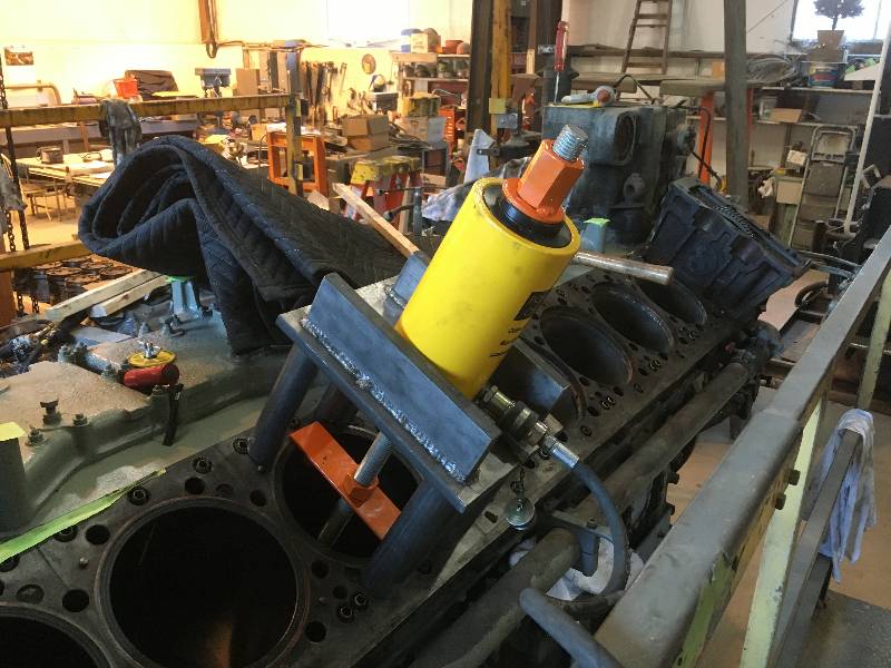
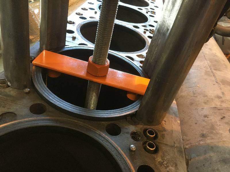
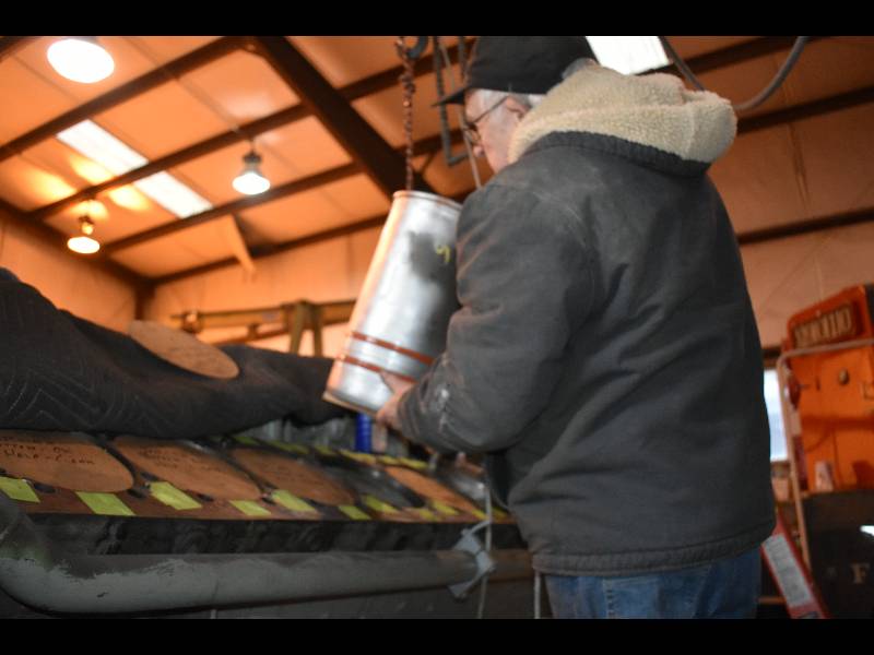
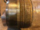
The next order of
business was the removal of all of the liners. This was
necessary because we knew that some of them were defective and all of
them had 50 year old lower seals. The liners are
pushed
into the block and we knew that they would not be easy to remove so we
built a pulling rig that is powered by a 25 ton hydraulic jack.
By multiplying the area of the jacks piston and the
hydraulic pressure applied to it, we determined that it required 24,000
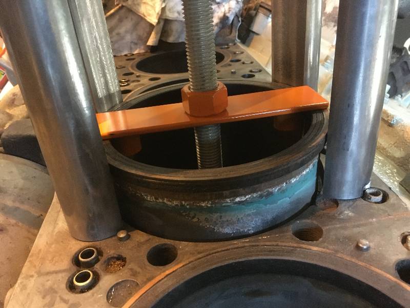
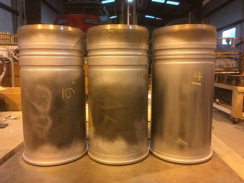
pounds of force to knock the liner loose. Photo #5 is of the
lower liner seal area with the old seals still in place and photo #6
shows 3 cleaned liners. It was interesting to see the
differences between the liners in the same engine.
 |
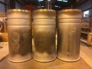 |
As soon as all of the
liners were out, volunteer Karl Swartz set to work cleaning
the sealing
surfaces
where the liners seat into the block. At the same time, we
cleaned the top of the block and the mating surfaces for the
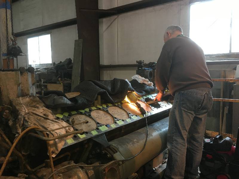
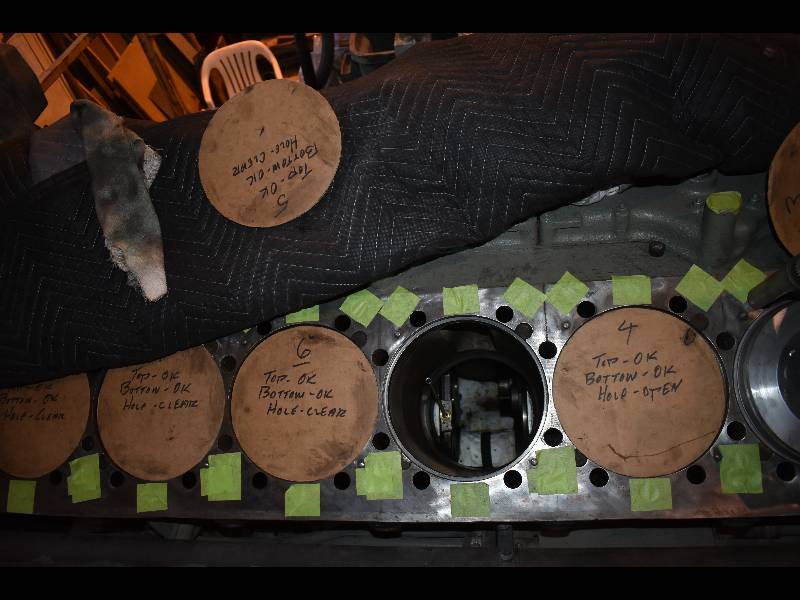
liners and made sure that the weep holes were open. We also
made cardboard covers for each of the open bores on which we could keep
notes on bore work. The green pieces of tape seen in the
photos are to protect the water and oil passenges which were also
cleaned.
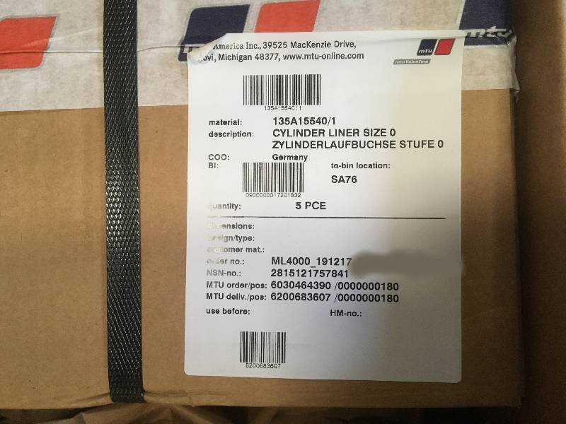
Early in March 2020,
we received our second order of parts which included the 5 new liners
and gaskets that we had not ordered the first time. Now,
things can get really serious.
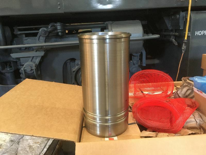
Now that we had all
16 liners available, we started to install them.
The 11
old liners were reinstalled in their original holes but were rotated 45
degrees per advice from our friends in the UK. All liners
received fresh lower liner seals (the orange bands in the first photo)
and were sealed at the top with a high quality copper infused silicone.
Hopefully, they will all pass the water test that will come
later.
 |
 |
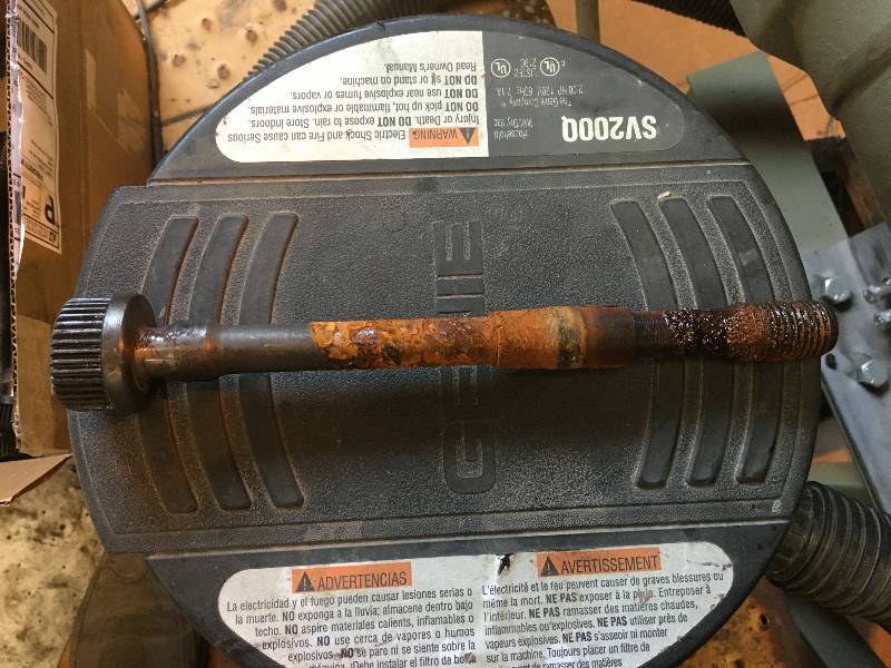
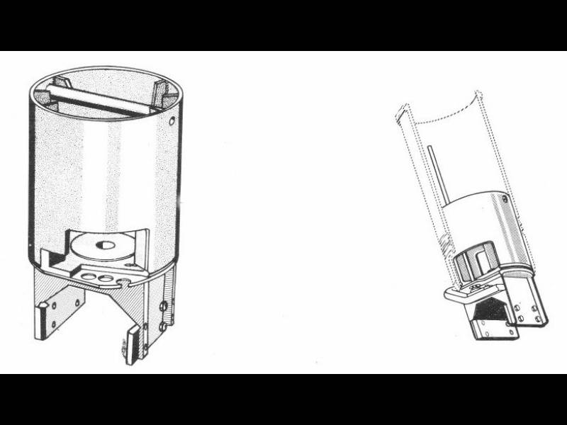
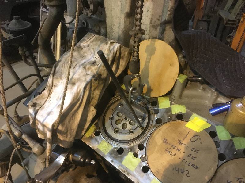
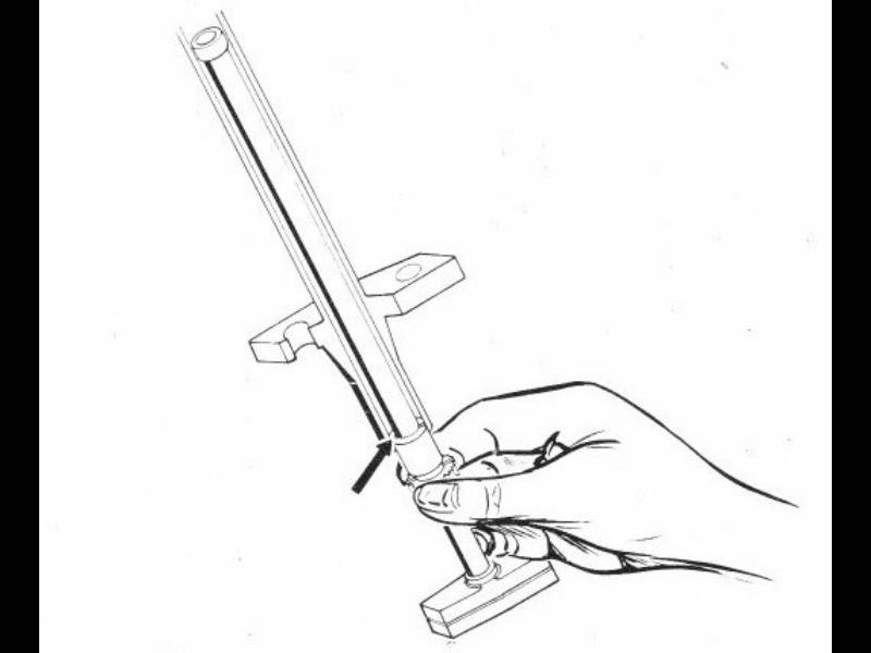
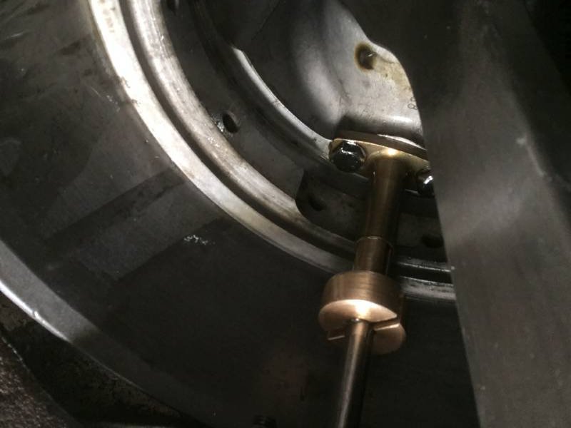
With the liners
in place, I could install and align the piston crown cooling (banjo)
lines that
were removed in order to clean the lower liner seal areas.
There is a very expensive tool available for this one time
operation but we came up with our own method. We took a
piston without its oil rings and crown, dropped it into the bore until
the rod bearing sat on the journal. This aligned the piston
to the crankshaft. While the piston was being lowered into
the bore, a rod was inserted in the cooling pipe. The rod has
a smaller diameter on its bottom end which is inserted into the cooling
line and aligns it to the pipe in the piston. The crankshaft
was then rotated 90 degrees to bring the piston down just far enough to
use a small alignment tool that volunteer machinist-bodyman Bill
Stimmerman made. The tool goes
around the line and up into the pipe thus fixing the line in place.
At that point, the mounting bolts for the line were tightened
so the line could not move. The piston was removed and the
line's mounting bolts firmly tightened. The whole process was
a bit cumbersome but gave us the result we wanted.
Return
To Main Page