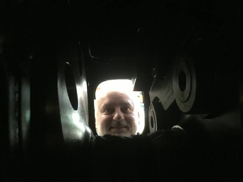
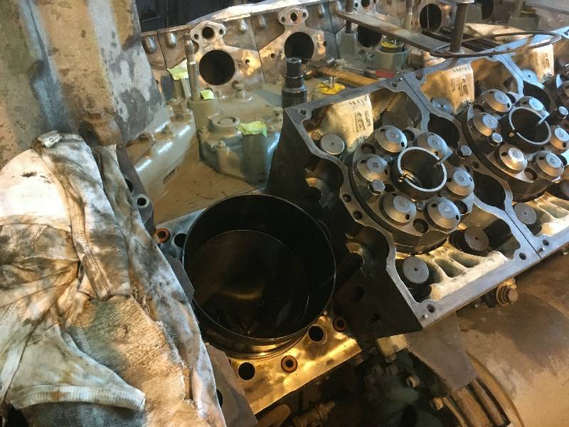
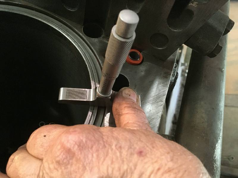
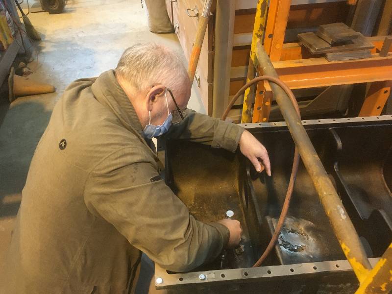
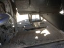
Here's Karl having a
look through the crankcase for any water leaking. We had to
carefully examine the inside of the liners as well as the mating
surfaces between the heads and the block.
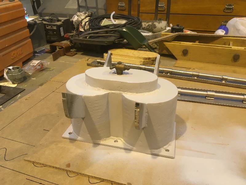
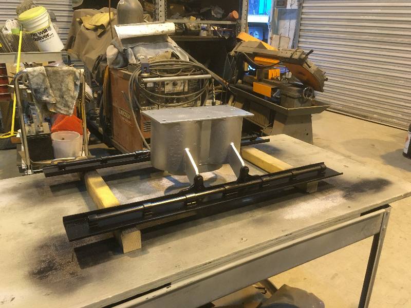
While not strictly
mechanical, I will put the little item in here so as not to lose the
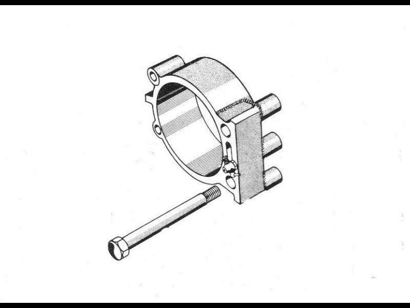
continuity of the project. 9010 was originally equipped with
a National Safety Appliance Company's Automatic Train Stop (ATS)
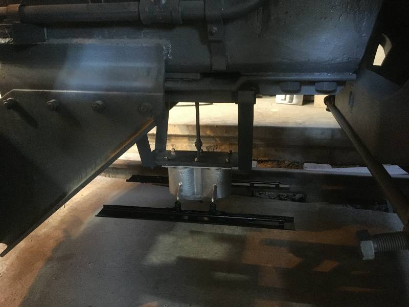
system. The most visible part of this apparatus was
the "Duplex Magnet Control Valve" that hung under the front
end of the locomotive. We have been kicking this around for
years but have never found good photographs of the valve or better yet,
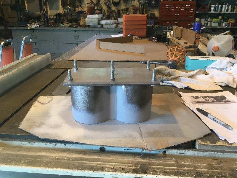
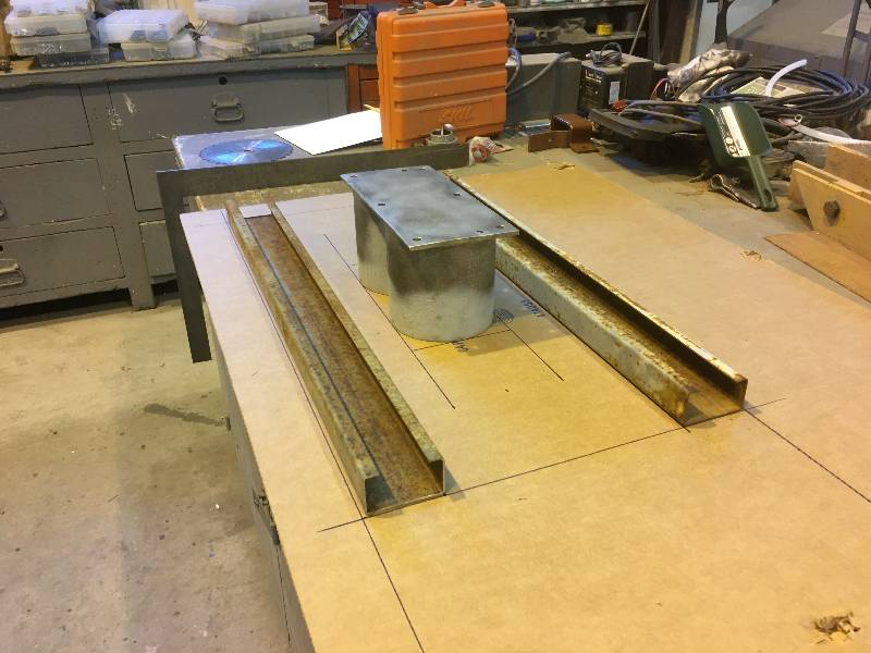
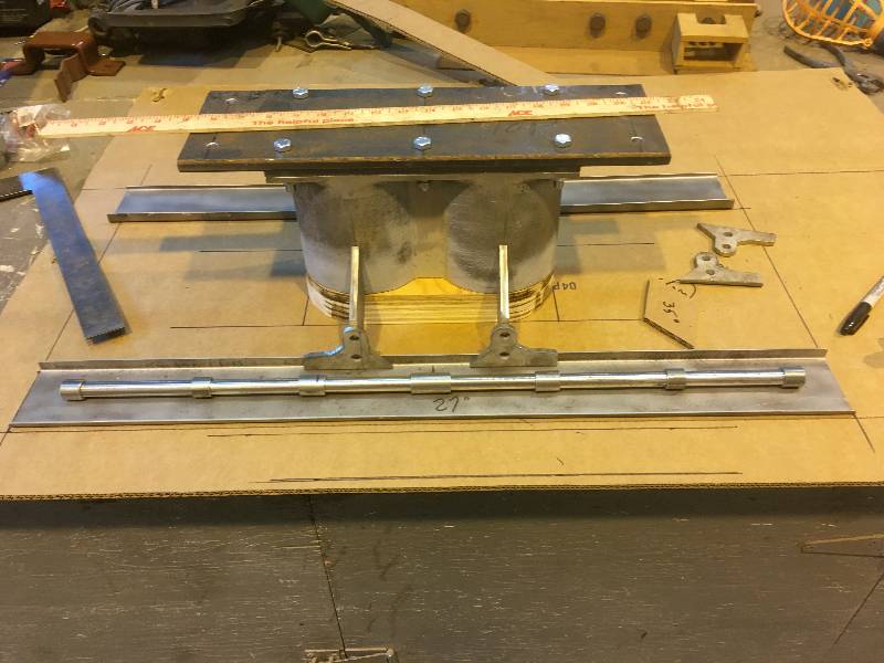
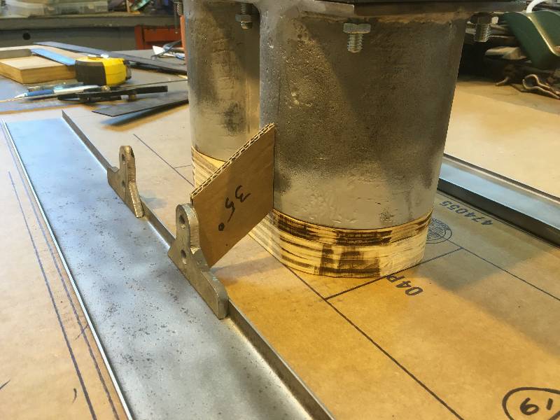
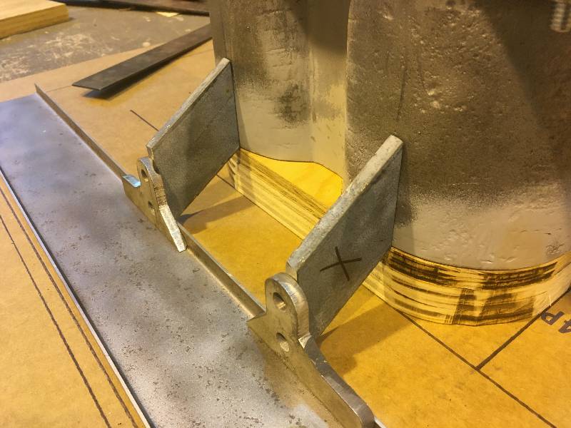
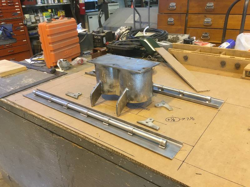
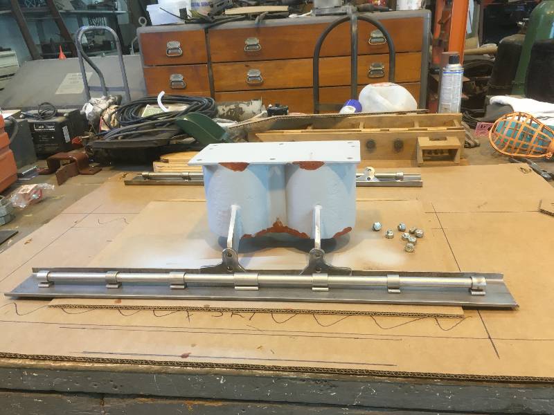
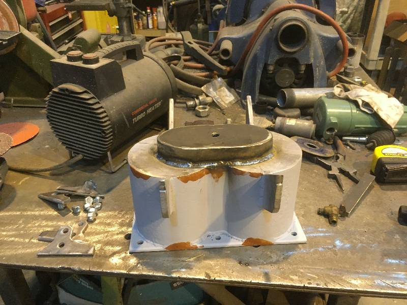
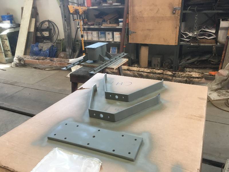
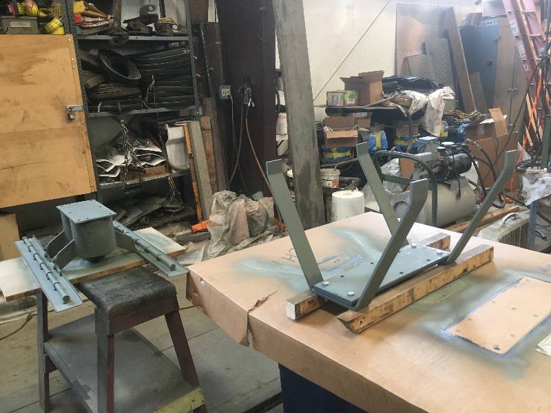
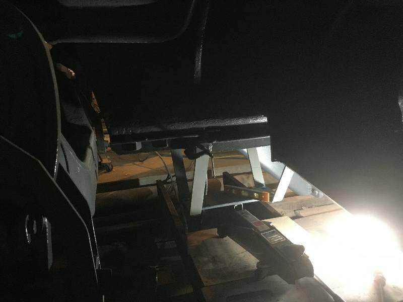
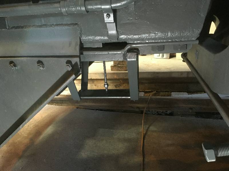
a complete valve. I decided to fabricate something
that would give an idea of what the device looked like and
our resident
forensicologist, Bob Zenk, created the plans.
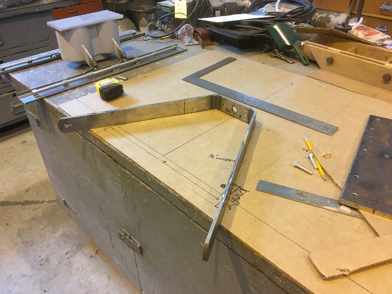
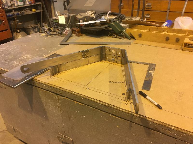
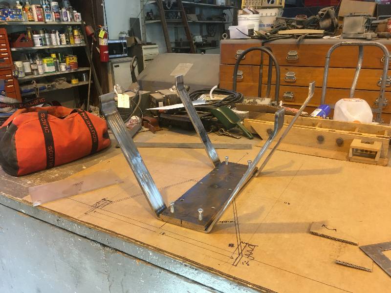
Much of the layout and
piece work was done at the home shop during the virus lock down.
The following
photographs were taken of the creative process.
 |
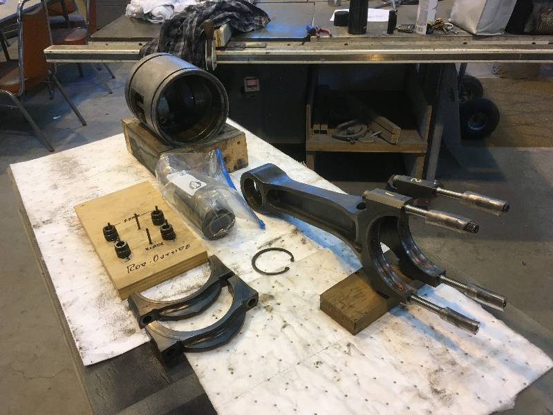
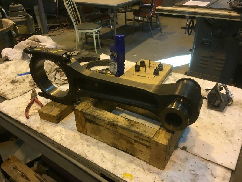
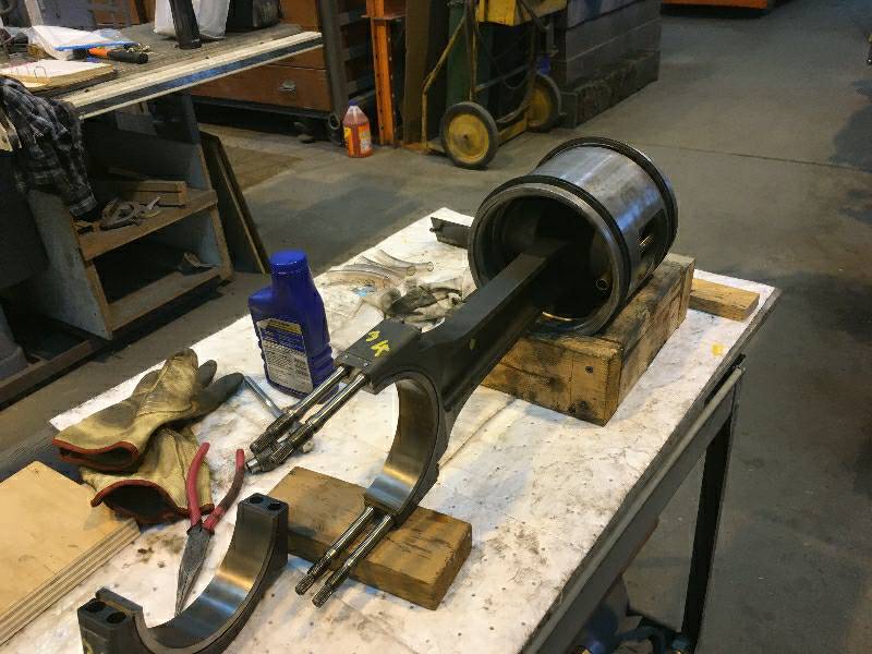
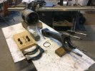
The next job on the
Maybach would be reinstalling all of the piston and rod assemblies.
Here is fork rod assembly #9 all taken apart for
cleaning.
New oil control rings will be installed on the piston before
installation. The rod bolts have splines as do the rod nuts.
The nuts and washers must be put back on the bolts from which
they came so the nuts are stamped with numbers that correspond with
locations on the rod caps. After this one is in place, the #1
blade rod will be next on the list.
 |
--
Update July 02, 2020 --
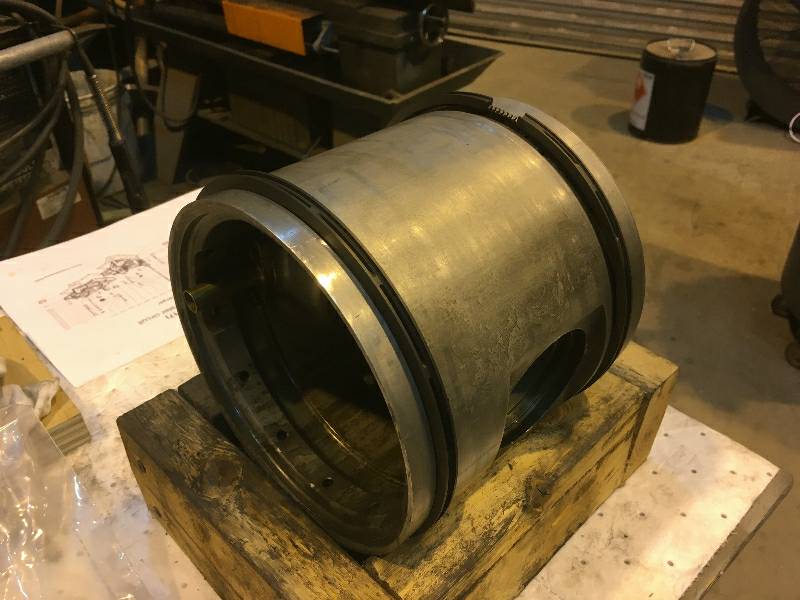
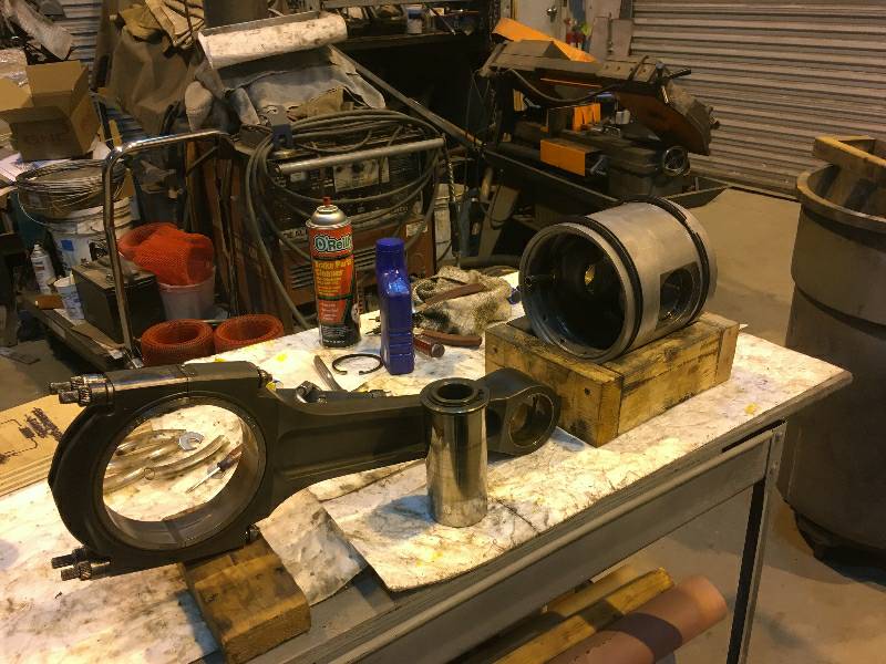
These are a few more photos of the #9 piston
and its fork rod. The plastic tubes seen covering the rod
bolts are there for two reasons. First, they protect the
crank journal against being scratched by the rod bolts and they also
hold the cut washers in place. The washers are there to
prevent the rod's upper bearing shell from falling out of the rod as
they are very heavy and need some help staying in
place. .
The shell's bearing surface is lubricated with a good quality
assembly lubricant. The third and fourth photos show the ring
compressor.
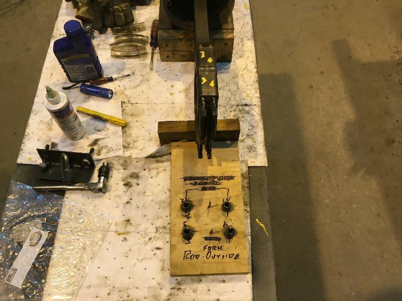
Here is piston/blade
rod #1 which is the mating assembly for #9. The piston pin is
removed to clean and lubricate the pin, piston and
rod.. Having the pin out and the piston off of the rod makes
it easier to install the bottom oil control ring without scratching the
piston. The last photo is of the peg board I used to keep
track of the rod nuts and washers.
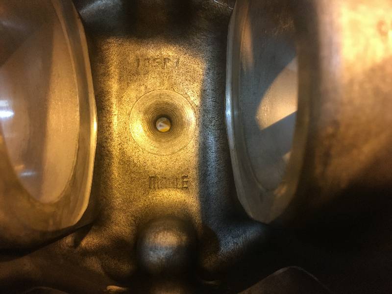
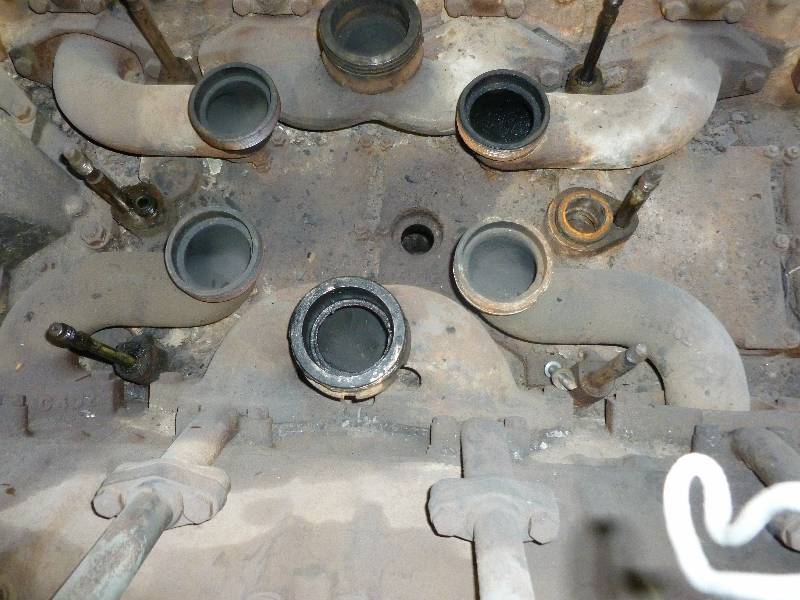
This is a photo of
the underside of a piston top. The lettering shows that the
piston was purchased from MAHLE GmbH, one of the largest automotive
suppliers in the world. Even a diversified manufacturer like
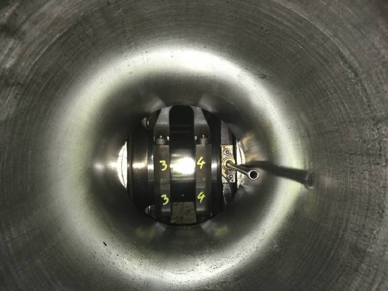
Maybach could not produce everything. Second photo is looking
down into a cylinder that has yet to receive the blade rod.
The light ring is caused by a camera flash. And
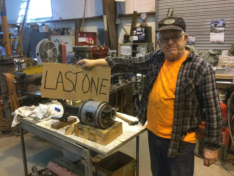
here is some guy celebrating the last piston to be installed.
After all of the
pistons and rod
assemblies were in, the next step would have been to tighten the rod
bolts but we could not do this because we were waiting for some special
wrenches. That process will be covered later. We
turned to
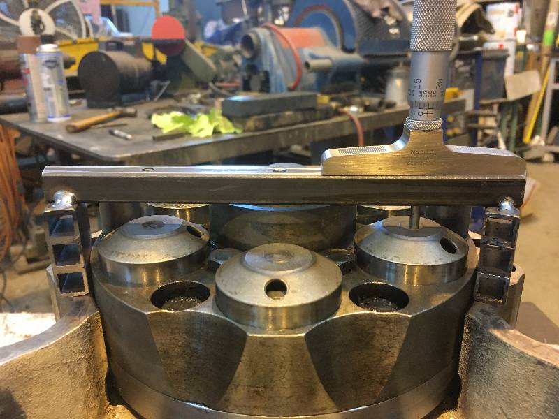
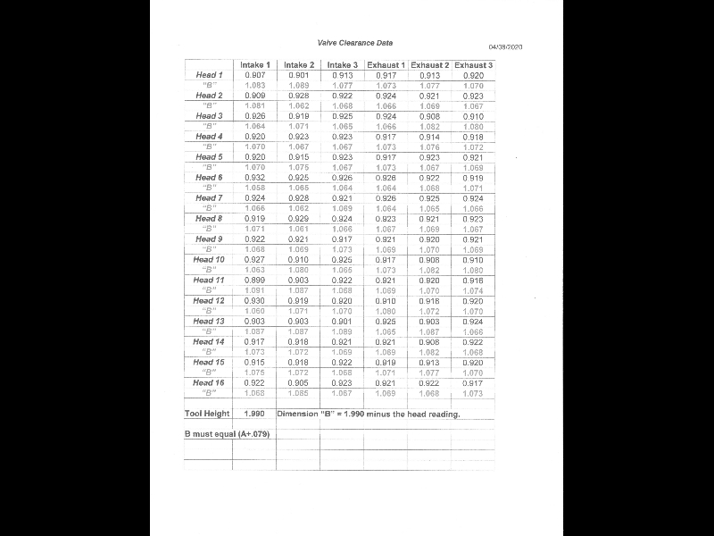
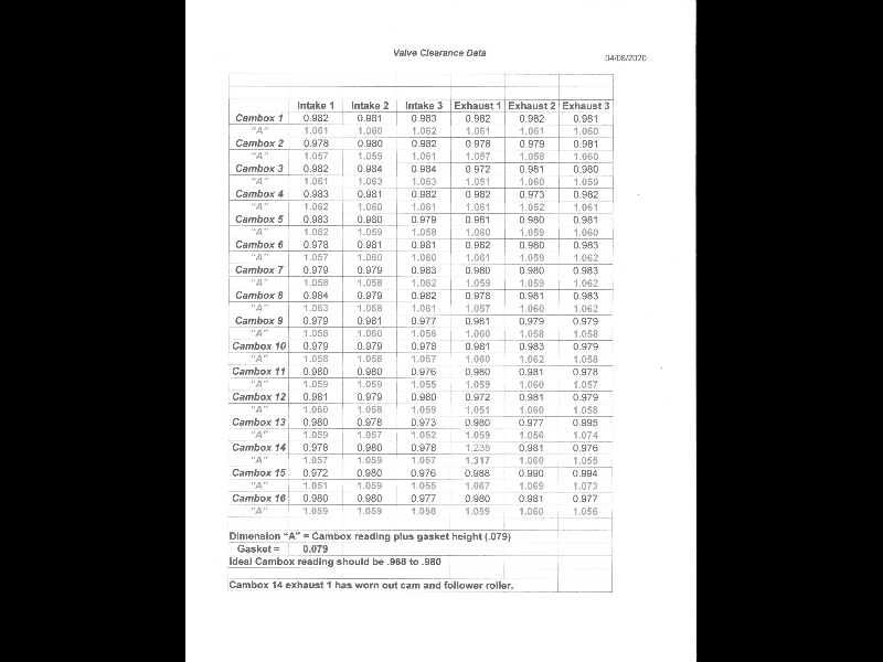
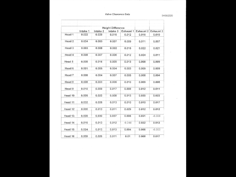
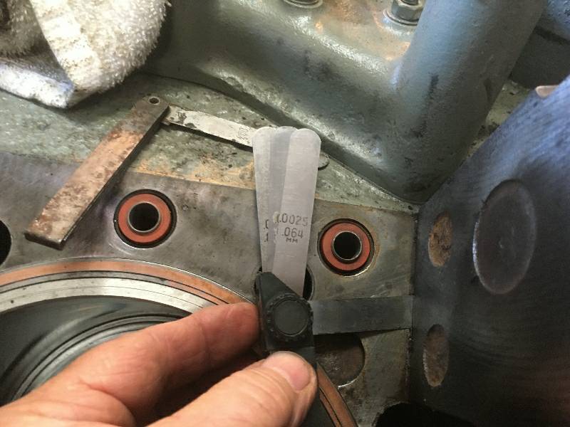
dealing with the "crush rings". The Maybach does not use a
head
gasket as such. It has a copper coated cast iron ring that
sits
in a groove between the cylinder liner and the block. The
depth
of each of the 16 grooves had to be measured and recorded.
Once
all of them were measured, crush rings of the proper thickness could be
chosen. One at a time, the proper ring was installed in a
groove,
the head installed and a measurement taken of the distance between the
head and the block, at all 4 surfaces - front, left, back and right.
This distance had to be between .003" and .005".
Once the
measurement was noted, the head was partially torqued down and the
measurement repeated. As long as the distance did not
compress to
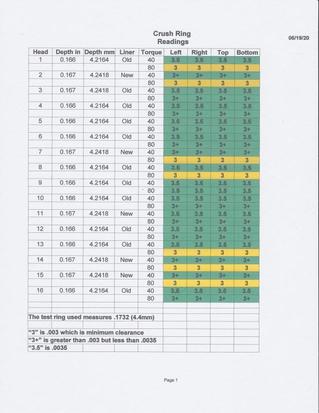
less than .003", all was good. We were very fortunate that
all 16
of the measurements fell within the normal bounds of a 4.4mm (.173")
thick crush ring. We had a selection of rings to use for test thanks to
our crew member Rob Fern from the UK. All of this
measuring work resulted in the chart seen in photo #3.
--
Update August 12, 2020 --
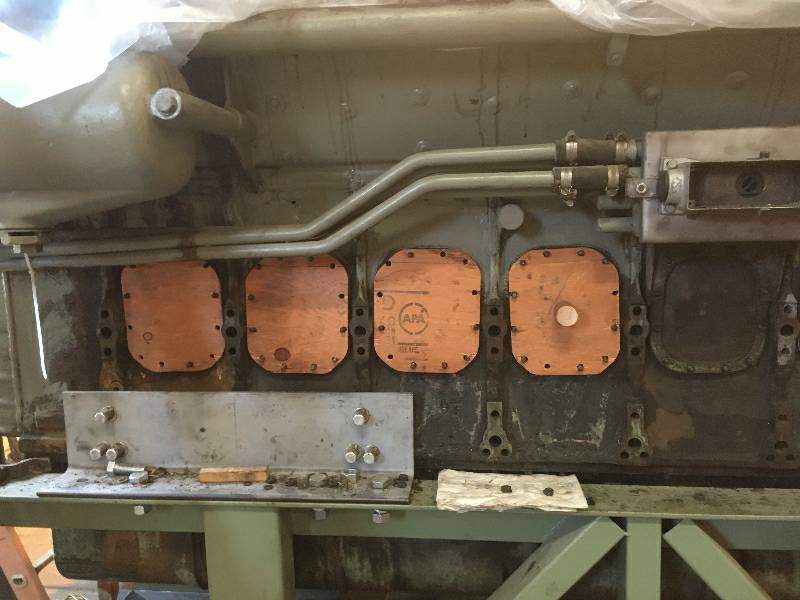
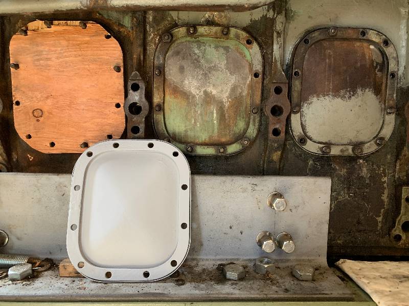
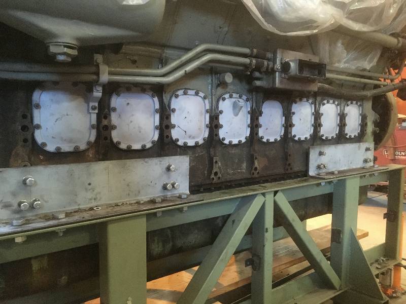
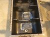
Karl has been busy with a project on the
engine crankcase.
There are 16 inspection doors, one for each cylinder.
These
doors and their studs have been a source of oil leaks. Karl
is
removing
all 16 studs from each door opening, cleaning the studs, cleaning the
holes and then putting the studs back using a good thread sealer.
While the studs are out of the block, he has
cleaned the sealing surface of the old gasket material. The
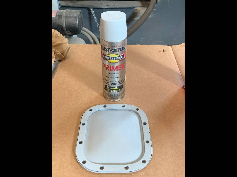
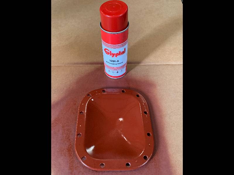
door are getting a much needed bead blasting and then paint on
the
outside and a coat of Glyptal on the inside. Hopefully, we
will
eliminate the oil leaks that used to affect the doors.
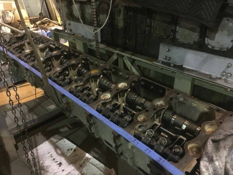
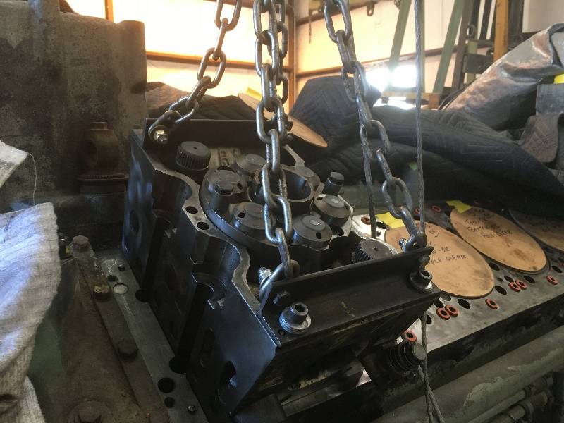
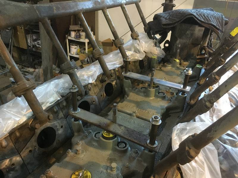
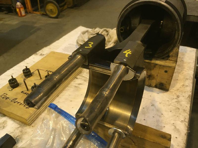
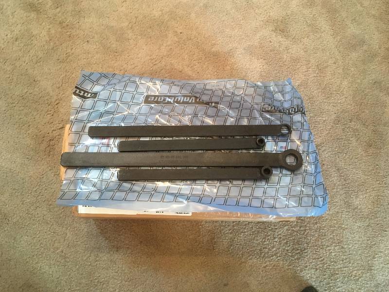
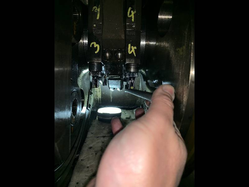
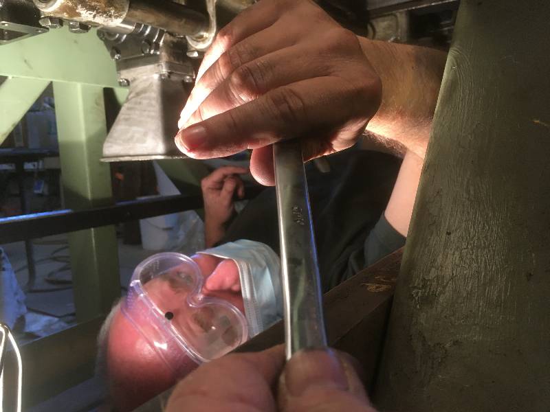
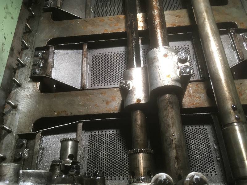
With
the arrival of the long handled
connecting rod bolt tools, we were able to start tightening the bolts.
These bolt are not tightened to a torque
specification but rather to a measurement of stretch.
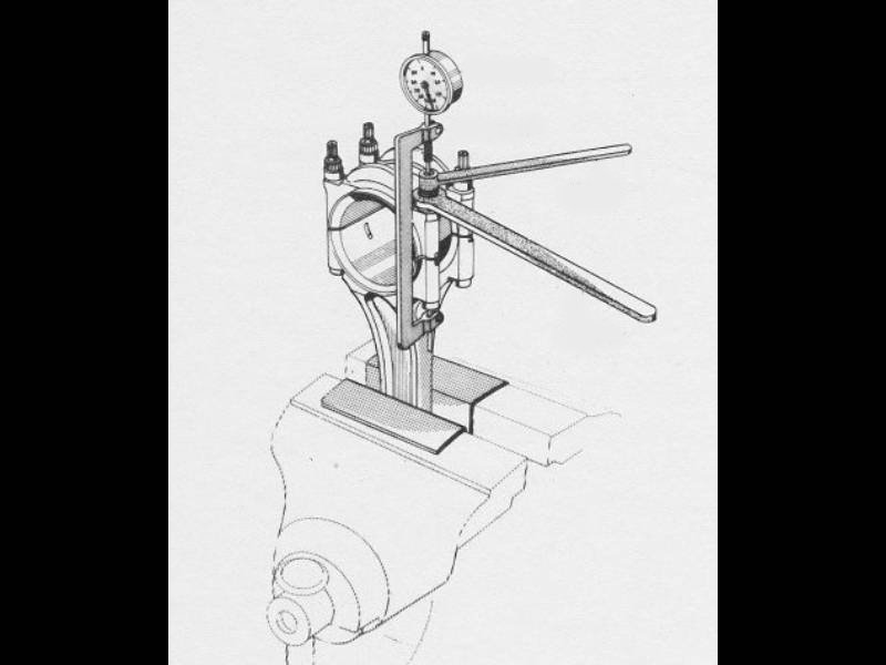
At the factory, a technician would mount the rod with its
bearing and caps in a vise. The nuts would be tightened while
watching an instrument that was measuring the amount each bolt
stretched under tension. When the proper amount of stretch
was achieved, the end of the rod bolt and nut were marked with a sort
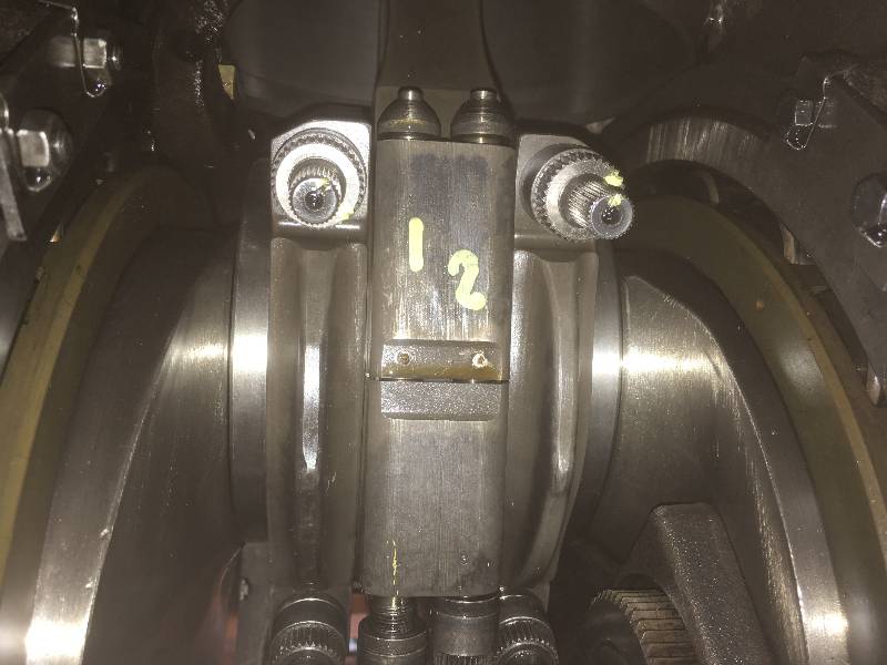
of chisel. Our challenge was to return those marks to their
proper alignment on each bolt and nut combination. The first
thing to do was put ink marks on the notches in the nuts and
bolts
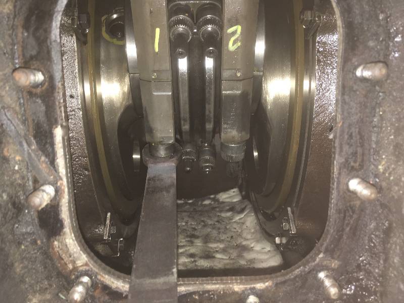
so the notches would be easier to see. The 4th photo shows
one of
the wrenches on the serrated nut. In this case, the other
wrench
would be holding the rod bolt from the other side of the block while
one of us tightens the nut. Needless to say, getting photos
of
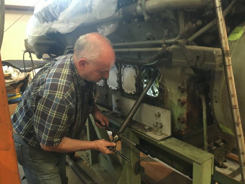
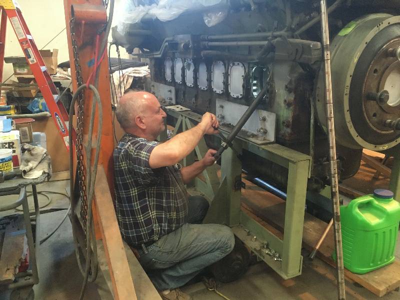
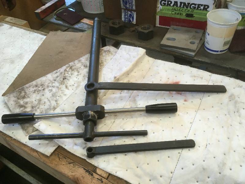
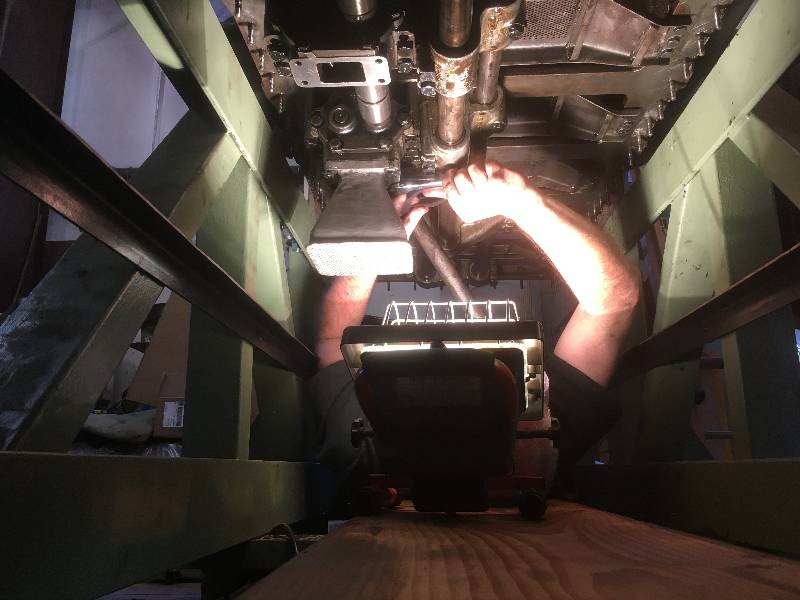
this operation was difficult. The wrenches are used to
tighten
the rod bolt nuts on one side of the rod while our "T" handle wrenches
are used to tighten the other nuts. In an ideal situation,
the
engine block would be mounted in a rotisserie engine stand which would
hold the block straight up in the air and one could use the "T" handle
wrenches on all of the rod bolts and nuts. Karl worked on the
left side while I worked on the right. We came up with a
system
that works quite well.
--
Update December 12, 2020 --
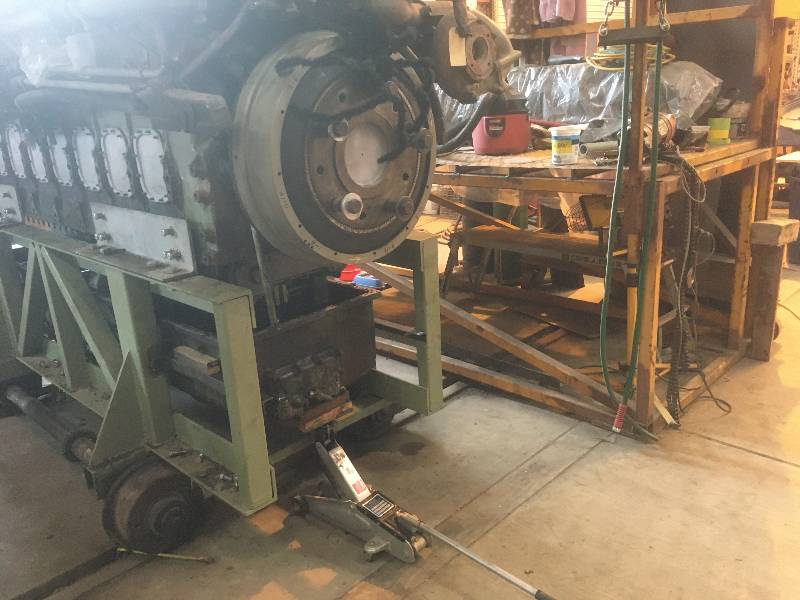
With all of the rod
bolts tightened, we were able to clean out the lower part of the block
and re-install the oil pan. Karl took on the job of cleaning
the
gasket surface on the block and putting the oil pickups back on.
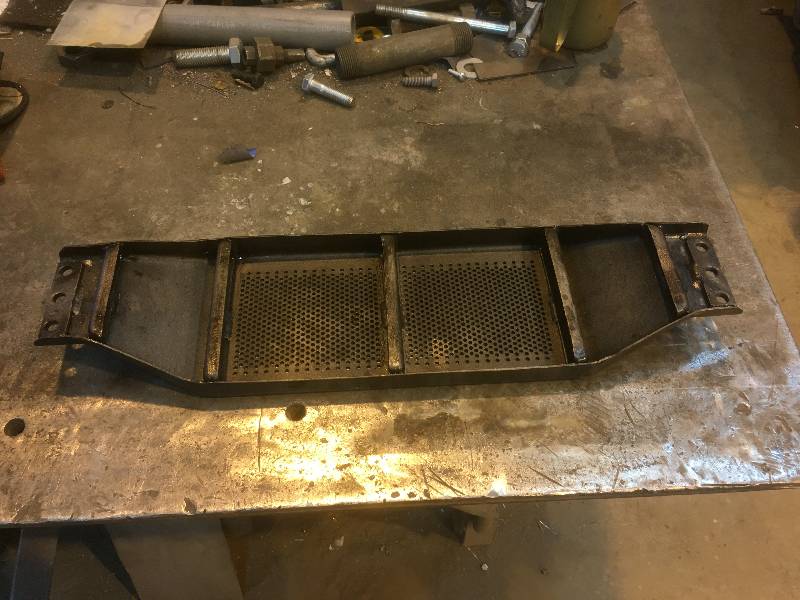
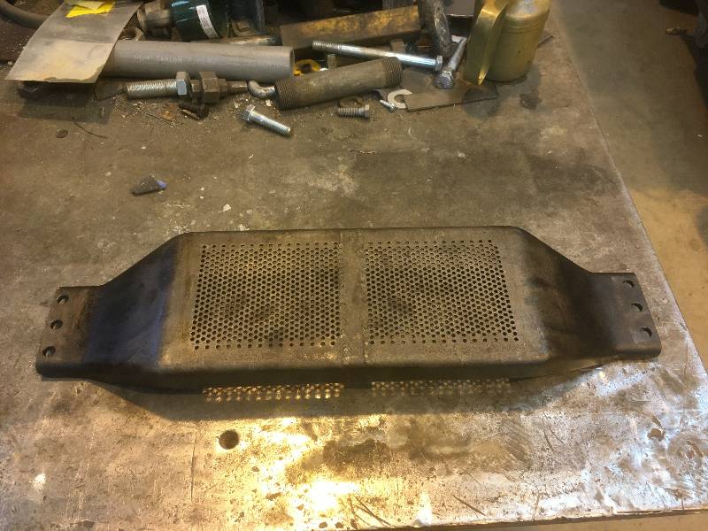
When this work was done, I put all of the windage
trays back on. This completed our work on the lower part of
the engine block so we turned our attention to the oil pan.
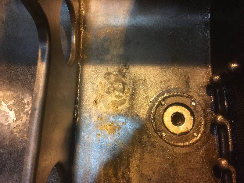
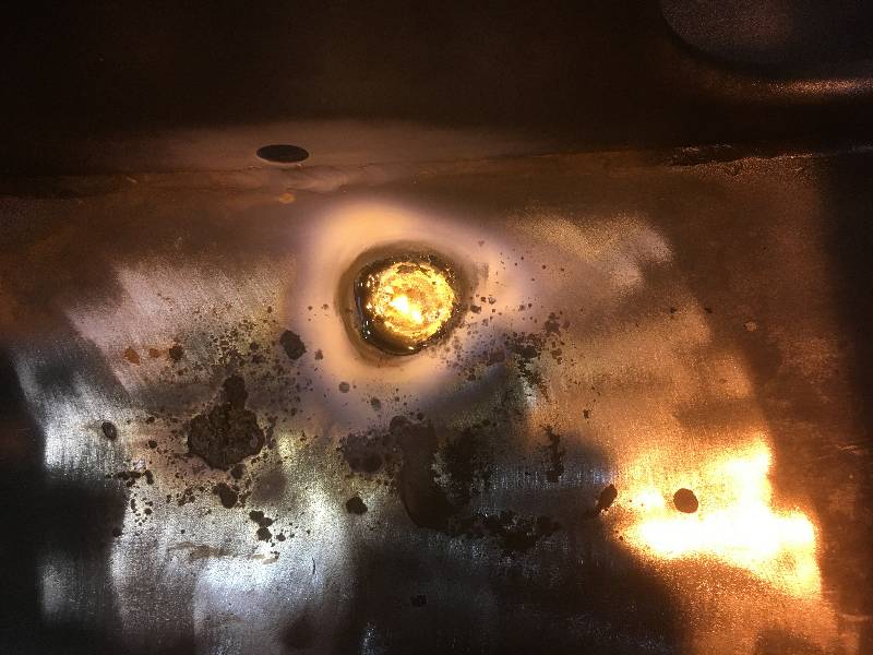
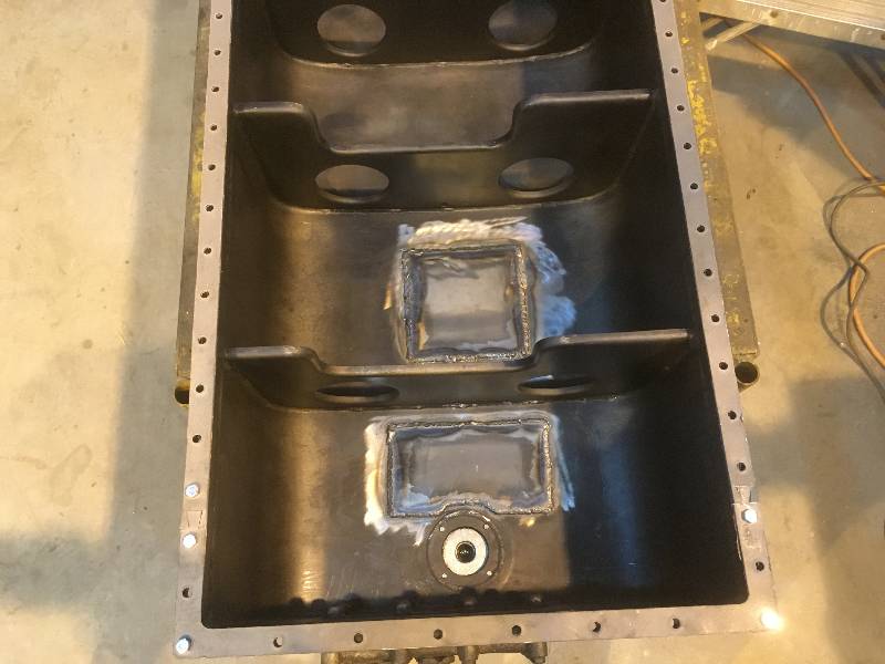
Preparing
the pan included wiping it out with mineral spirits and while doing so,
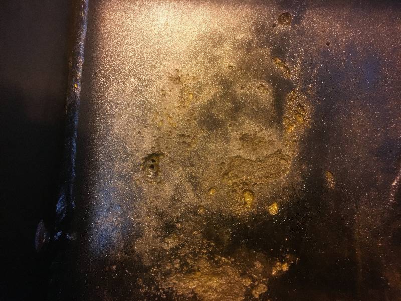
I noticed a drip or 2 on the shop floor. An examination of
the
pan bottom revealed that there were 2 corroded areas in the metal and
several spots where the metal had rotted all the way through.
How
the pan did not leak oil is a mystery but there were probably chunks of
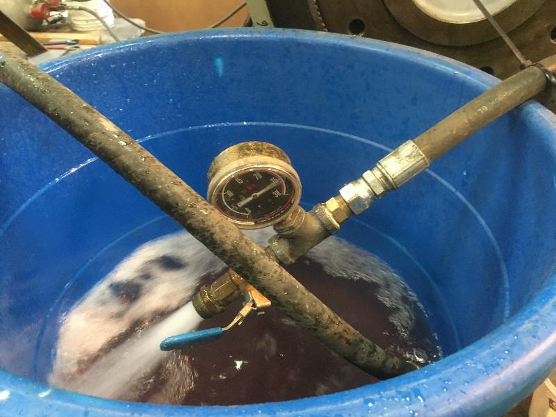
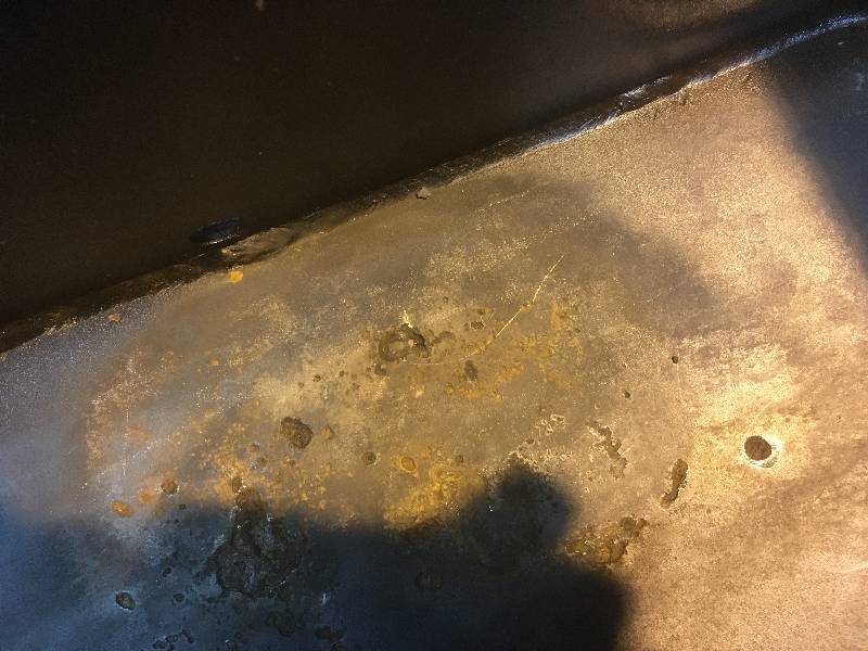
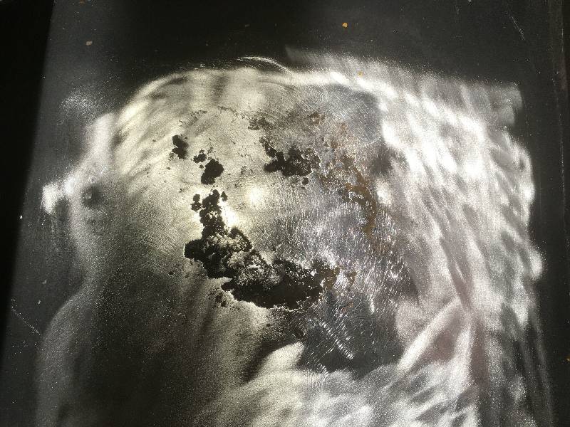
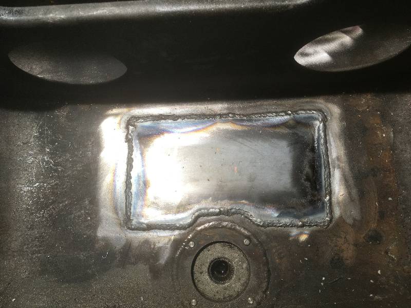
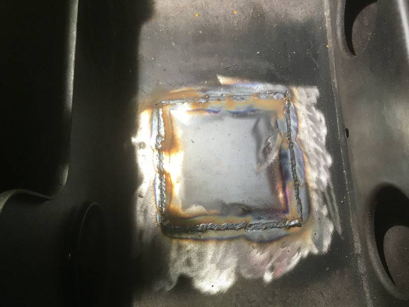
crud plugging the holes. I made an
attempt to braze the bad
areas but this was not successful due to cracking of the base material.
Karl is seen cleaning the base metal before I made patches
and MIG welded them over the entire corroded
areas. Submerging the areas in water for several hours with
no
leaking proved the repair.
 |
Karl cleaned the top
edge of the pan, applied a coat of Permatex #2 and we put the pan back
in place. All 88 pan nuts were torqued and we turned our
attention to the side covers. Karl had previously cleaned all
of the covers and block gasket surfaces. All of the studs
were removed, cleaned and reinstalled with sealer as the studs
penetrate into the inside of the block and many were seen to have been
leaking. New gaskets were applied with the covers and the
nuts properly torqued.
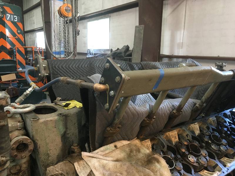
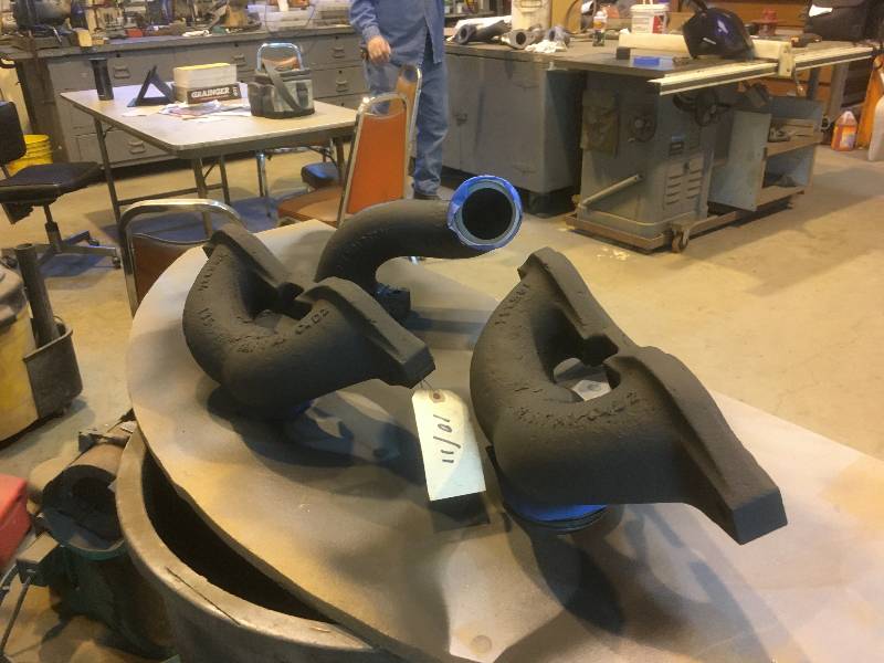
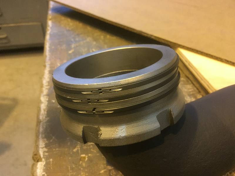
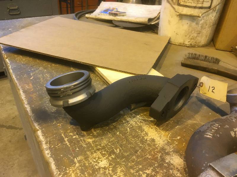
Bill has been working
on the exaust elbows. He cleaned them all, and applied new
sealing rings to the sealing inserts. These inserts go up
into the bottom of the turbochargers and are intended to provide an
exhaust gas seal.
Return
To Main Page